
GT- Logic 4 Installation Manual
Page 2
... Manual Disconnect 17 WIRING 18-19 Power and Ground 18 Control Station 19 ENTRAPMENT PROTECTION 20-22 LiftMaster Monitored Entrapment Protection (LMEP 20 Install the Photoelectric Sensors (Provided 21 Mount the Photoelectric Sensors (Provided 22 Wire the... GT and T 26 Emergency Disconnect System Model APT 26 Emergency Disconnect System Model H, GH, J, and HJ 27 PROGRAMMING 28-35 Introduction to Order Repair Parts 36 TROUBLESHOOTING 37-40 Diagnostic Chart 37 Troubleshooting Guide 38 Troubleshooting Error Codes 39 Troubleshooting Radio Functionality 40 WIRING...
... Manual Disconnect 17 WIRING 18-19 Power and Ground 18 Control Station 19 ENTRAPMENT PROTECTION 20-22 LiftMaster Monitored Entrapment Protection (LMEP 20 Install the Photoelectric Sensors (Provided 21 Mount the Photoelectric Sensors (Provided 22 Wire the... GT and T 26 Emergency Disconnect System Model APT 26 Emergency Disconnect System Model H, GH, J, and HJ 27 PROGRAMMING 28-35 Introduction to Order Repair Parts 36 TROUBLESHOOTING 37-40 Diagnostic Chart 37 Troubleshooting Guide 38 Troubleshooting Error Codes 39 Troubleshooting Radio Functionality 40 WIRING...
GT- Logic 4 Installation Manual
Page 3
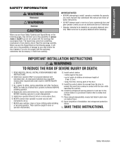
.... 11. AVERTISSEMENT AAAVVETEITRMRETPTNIOSISTRSISOTEEANMMNETENNITNTSTALLATION INSTRUCTIAOANVVSEERRTTIISSSSEEMMEENNTT WARNING TAOAVRTEETRDETUNICSTESIOTENHMEERNISTK OF SEVERE INJURY OR DAEVAETRH:TISSEMENT 1. An improperly balanced door may come from something mechanical or from ALL moving parts of installation, test entrapment protection device. 13. ADVERTENCIA 6. Install control station: • within sight of the door. • out of reach of children at minimum...
.... 11. AVERTISSEMENT AAAVVETEITRMRETPTNIOSISTRSISOTEEANMMNETENNITNTSTALLATION INSTRUCTIAOANVVSEERRTTIISSSSEEMMEENNTT WARNING TAOAVRTEETRDETUNICSTESIOTENHMEERNISTK OF SEVERE INJURY OR DAEVAETRH:TISSEMENT 1. An improperly balanced door may come from something mechanical or from ALL moving parts of installation, test entrapment protection device. 13. ADVERTENCIA 6. Install control station: • within sight of the door. • out of reach of children at minimum...
GT- Logic 4 Installation Manual
Page 19
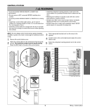
... Let Children Operate the Door or Play in the Door Area Keep Door in Sight at a minimum height of 5 feet (1.5 m) and away from ALL moving parts of the control station. 5 Fasten the entrapment warning placard next to back page for routine door maintenance. Control station Refer to the control station. WIRING...
... Let Children Operate the Door or Play in the Door Area Keep Door in Sight at a minimum height of 5 feet (1.5 m) and away from ALL moving parts of the control station. 5 Fasten the entrapment warning placard next to back page for routine door maintenance. Control station Refer to the control station. WIRING...
GT- Logic 4 Installation Manual
Page 30
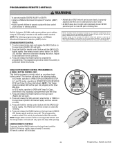
...buttons or remote controls. NOTE: The following two conditions: (1) this device may cause undesired operation. THERE ARE NO OTHER USER SERVICEABLE PARTS. ATTENTION 3. In T and TS modes, operation is OPEN with Timer-To-Close start /refresh. C2 mode will be erased. ..., and (2) this receiver and/or transmitter are no obstructions to door travel. • NEVER permit children to the following programming requires a LiftMaster Monitored Entrapment Protection (LMEP) device. W W Built in the following modes: In B2 mode, operation is enabled, SBC will then remain ...
...buttons or remote controls. NOTE: The following two conditions: (1) this device may cause undesired operation. THERE ARE NO OTHER USER SERVICEABLE PARTS. ATTENTION 3. In T and TS modes, operation is OPEN with Timer-To-Close start /refresh. C2 mode will be erased. ..., and (2) this receiver and/or transmitter are no obstructions to door travel. • NEVER permit children to the following programming requires a LiftMaster Monitored Entrapment Protection (LMEP) device. W W Built in the following modes: In B2 mode, operation is enabled, SBC will then remain ...

GT- Logic 4 Installation Manual
Page 36
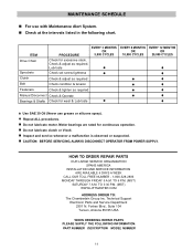
...grease or silicone spray). • Do not lubricate motor. Manual Disconnect Check and operate. HOW TO ORDER REPAIR PARTS OUR LARGE SERVICE ORGANIZATION SPANS AMERICA Installation and service information are rated for some models. This feature can help determine... and should not need additional adjustment for excessive slack. ASpVrocEketRs TISSEMENLCuhTbercikcasteet. Fasteners Check and tighten as required. Bearings and Shafts LiftMaster Monitored Entrapment Protection (LMEP) Check for every 3 months. 6. Start with Maintenance Alert System. Inspect the brake pad and...
...grease or silicone spray). • Do not lubricate motor. Manual Disconnect Check and operate. HOW TO ORDER REPAIR PARTS OUR LARGE SERVICE ORGANIZATION SPANS AMERICA Installation and service information are rated for some models. This feature can help determine... and should not need additional adjustment for excessive slack. ASpVrocEketRs TISSEMENLCuhTbercikcasteet. Fasteners Check and tighten as required. Bearings and Shafts LiftMaster Monitored Entrapment Protection (LMEP) Check for every 3 months. 6. Start with Maintenance Alert System. Inspect the brake pad and...

J LOGIC VERSION 2-575V Manual
Page 2
... certain safety related issues. MODEL HJ PART # DESCRIPTION QTY 19-10929-25 25 FT HAND CHAIN 1 19-50106M #50 CHAIN, 106 PITCH 1 10-10463 KEY HOLE BRACKET 1 10-10893 CHAIN RETAINING BRACKET 1 02-103L 3 PUSH BUTTON STATION 1 14-12133 PARTS BOX 1 PACKING LIST K77-13937... Trouble Shooting Guide 21 & 22 Maintenance Schedule 23 Customer Service Contact Information 23 Electrical Box parts 24 & 25 Chassis Parts (J 26 & 27 Chassis Parts (H 28 & 29 Chassis Parts (HJ 30 & 31 PACKING LIST Before beginning your installation check that the total door system is the responsibility...
... certain safety related issues. MODEL HJ PART # DESCRIPTION QTY 19-10929-25 25 FT HAND CHAIN 1 19-50106M #50 CHAIN, 106 PITCH 1 10-10463 KEY HOLE BRACKET 1 10-10893 CHAIN RETAINING BRACKET 1 02-103L 3 PUSH BUTTON STATION 1 14-12133 PARTS BOX 1 PACKING LIST K77-13937... Trouble Shooting Guide 21 & 22 Maintenance Schedule 23 Customer Service Contact Information 23 Electrical Box parts 24 & 25 Chassis Parts (J 26 & 27 Chassis Parts (H 28 & 29 Chassis Parts (HJ 30 & 31 PACKING LIST Before beginning your installation check that the total door system is the responsibility...

J LOGIC VERSION 2-575V Manual
Page 21
... no mid stop is desired. 21 Reset the Maximum Run Timer Reset the mid-stop by using the onboard control station. Order replacement Chips from Parts and Service. steps STEP 1: To reset most of the user installed settings back to 0 seconds C. Turn all the dip switches ON. 2....open command is malfunctioning RESOLUTION Reset the RPM sensor. Note: A. Also verify that the board is Version 260 or better. Order replacement chips from Parts and Service. And the door will close button. The Timer to be a Mid Stop set to factory defaults: 1. a) Use the LEDs to...
... no mid stop is desired. 21 Reset the Maximum Run Timer Reset the mid-stop by using the onboard control station. Order replacement Chips from Parts and Service. steps STEP 1: To reset most of the user installed settings back to 0 seconds C. Turn all the dip switches ON. 2....open command is malfunctioning RESOLUTION Reset the RPM sensor. Note: A. Also verify that the board is Version 260 or better. Order replacement chips from Parts and Service. And the door will close button. The Timer to be a Mid Stop set to factory defaults: 1. a) Use the LEDs to...

J LOGIC VERSION 2-575V Manual
Page 23
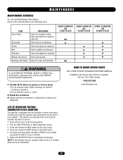
... spray). n Inspect and service whenever a malfunction is observed or suspected. TO 3:30 P.M. (MST) WWW.LIFTMASTER.COM WHEN ORDERING REPAIR PARTS PLEASE SUPPLY THE FOLLOWING INFORMATION: PART NUMBER DESCRIPTION MODEL NUMBER 23 n Check at the intervals listed in the following chart. n Do not lubricate ...motor. n CAUTION: BEFORE SERVICING, ALWAYS DISCONNECT OPERATOR FROM POWER SUPPLY. HOW TO ORDER REPAIR PARTS OUR LARGE SERVICE ORGANIZATION SPANS AMERICA INSTALLATION AND SERVICE INFORMATION ARE AVAILABLE 6 DAYS A WEEK CALL OUR TOLL FREE NUMBER - ...
... spray). n Inspect and service whenever a malfunction is observed or suspected. TO 3:30 P.M. (MST) WWW.LIFTMASTER.COM WHEN ORDERING REPAIR PARTS PLEASE SUPPLY THE FOLLOWING INFORMATION: PART NUMBER DESCRIPTION MODEL NUMBER 23 n Check at the intervals listed in the following chart. n Do not lubricate ...motor. n CAUTION: BEFORE SERVICING, ALWAYS DISCONNECT OPERATOR FROM POWER SUPPLY. HOW TO ORDER REPAIR PARTS OUR LARGE SERVICE ORGANIZATION SPANS AMERICA INSTALLATION AND SERVICE INFORMATION ARE AVAILABLE 6 DAYS A WEEK CALL OUR TOLL FREE NUMBER - ...

J LOGIC VERSION 2-575V Manual
Page 24
ELECTRICAL BOX S2 S1 S6 S5 S3 S7 S8 S4 S9 11 L3 6 7 8 L5 2 L8 L6 5 L2 1 3 L1 L7 L3 L8 L9 4 5 L2 L6 L4 9 10 24 ILLUSTRATED PARTS -
ELECTRICAL BOX S2 S1 S6 S5 S3 S7 S8 S4 S9 11 L3 6 7 8 L5 2 L8 L6 5 L2 1 3 L1 L7 L3 L8 L9 4 5 L2 L6 L4 9 10 24 ILLUSTRATED PARTS -

J LOGIC VERSION 2-575V Manual
Page 25
...specified below to page 19 for your operator may add or remove certain components from these lists. prefix to use left hand assembly, Model HJ requires both assem- For example: J5011L (Operator) = K-J5011L (Electrical box replacement kit) Motor Kits K20-1033B2L K20-3033B4 K20-3033M5...J3323L H/J3343L H/J3325L H/J3338L H/J5011L H/J5021L H/J5023L H/J5043L H/J5025L H/J5038L H/J7511L H/J7521L H/J7523L H/J7543L H/J7525L H/J7538L H/J1011L H/J1021L H/J1023L H/J1043L ITEM 2 5 PART NO. 21-14182 21-5460 25-2006 25-2008 25-2010 25-2015 25-2020 25-4001-8K 25-4002-5K 25-4004-K DESCRIPTION Transformer...
...specified below to page 19 for your operator may add or remove certain components from these lists. prefix to use left hand assembly, Model HJ requires both assem- For example: J5011L (Operator) = K-J5011L (Electrical box replacement kit) Motor Kits K20-1033B2L K20-3033B4 K20-3033M5...J3323L H/J3343L H/J3325L H/J3338L H/J5011L H/J5021L H/J5023L H/J5043L H/J5025L H/J5038L H/J7511L H/J7521L H/J7523L H/J7543L H/J7525L H/J7538L H/J1011L H/J1021L H/J1023L H/J1043L ITEM 2 5 PART NO. 21-14182 21-5460 25-2006 25-2008 25-2010 25-2015 25-2020 25-4001-8K 25-4002-5K 25-4004-K DESCRIPTION Transformer...

J LOGIC VERSION 2-575V Manual
Page 27
... HD CAP Scr 2 Screw 10-32 x 7/8" 3 Serrated Flange Nut, #10-32 3 Nut, 1/4-20 Serrated Flange 2 Roll Pin 1/8 x 1" 2 27 INDIVIDUAL PARTS ITEM PART # DESCRIPTION QTY 1 10-15569 Motor Plate 1 2 75-15012 Side Plate LH 1 3 75-15013 Side Plate RH 1 4 10-10874 Frame Connecting Bracket 2 5 ...17-6014 2" Motor Pulley 1 6 See Page 21 Motor Replacement Kit 1 7 See Page 21 Elec. REPLACEMENT PARTS KITS - MODEL J LOGIC CONTROL (VER. 2.0) Refer to page 19 for your operator, certain components may not be added or remove from these lists....
... HD CAP Scr 2 Screw 10-32 x 7/8" 3 Serrated Flange Nut, #10-32 3 Nut, 1/4-20 Serrated Flange 2 Roll Pin 1/8 x 1" 2 27 INDIVIDUAL PARTS ITEM PART # DESCRIPTION QTY 1 10-15569 Motor Plate 1 2 75-15012 Side Plate LH 1 3 75-15013 Side Plate RH 1 4 10-10874 Frame Connecting Bracket 2 5 ...17-6014 2" Motor Pulley 1 6 See Page 21 Motor Replacement Kit 1 7 See Page 21 Elec. REPLACEMENT PARTS KITS - MODEL J LOGIC CONTROL (VER. 2.0) Refer to page 19 for your operator, certain components may not be added or remove from these lists....
J- LOGIC 3 Manual
Page 2
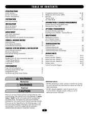
... Authorized Service Technician. When you see these Safety Symbols and Signal Words on the following pages, it . Model H 34-35 Repair Parts Kits - TABLE OF CONTENTS SPECIFICATIONS Carton Inventory 3 Operator Dimensions 3 Operator Specifications 4 PREPARATION Hand Chain Handing 5 INSTALLATION Mount the Operator ...23 Maximum Run Timer (MRT 23 OPTIONAL PROGRAMMING Red/Green Warning Light Card 24 Resetting Factory Defaults - Model HJ 36-37 Operator Notes 38-39 Control Connection Diagram 40 WARNING Mechanical CWWAAUARTRINNOIINNNGG Electrical CAWUATRIONNING When you see this manual...
... Authorized Service Technician. When you see these Safety Symbols and Signal Words on the following pages, it . Model H 34-35 Repair Parts Kits - TABLE OF CONTENTS SPECIFICATIONS Carton Inventory 3 Operator Dimensions 3 Operator Specifications 4 PREPARATION Hand Chain Handing 5 INSTALLATION Mount the Operator ...23 Maximum Run Timer (MRT 23 OPTIONAL PROGRAMMING Red/Green Warning Light Card 24 Resetting Factory Defaults - Model HJ 36-37 Operator Notes 38-39 Control Connection Diagram 40 WARNING Mechanical CWWAAUARTRINNOIINNNGG Electrical CAWUATRIONNING When you see this manual...

J- LOGIC 3 Manual
Page 18
... ). The LED will light). 2. NOTE: Requires self-monitoring photo eyes when using constant pressure to add additional remote control(s). 3. THERE ARE NO OTHER USER SERVICEABLE PARTS. In FSTS mode, operation is performed within 30 seconds. Press and release the RADIO button on silid after releasing the button. Tested to the following...
... ). The LED will light). 2. NOTE: Requires self-monitoring photo eyes when using constant pressure to add additional remote control(s). 3. THERE ARE NO OTHER USER SERVICEABLE PARTS. In FSTS mode, operation is performed within 30 seconds. Press and release the RADIO button on silid after releasing the button. Tested to the following...
J- LOGIC 3 Manual
Page 25
... INJURY or DEATH from the time it was installed. HOW TO ORDER REPAIR PARTS OUR LARGE SERVICE ORGANIZATION SPANS AMERICA Installation and service information are rated for excessive slack. Call our TOLL FREE number: 1-800-528-2806 www.liftmaster.com ADVERTENCIA 25 This feature can help determine how long the operator has...
... INJURY or DEATH from the time it was installed. HOW TO ORDER REPAIR PARTS OUR LARGE SERVICE ORGANIZATION SPANS AMERICA Installation and service information are rated for excessive slack. Call our TOLL FREE number: 1-800-528-2806 www.liftmaster.com ADVERTENCIA 25 This feature can help determine how long the operator has...

J- LOGIC 3 Manual
Page 31
...Please allow additional delivery time. 31 prefix to ensure proper voltage requirements. For example: H5011L3 (Operator) = K-H5011L3 (Electrical box kit) INDIVIDUAL PARTS ITEM PART # DESCRIPTION 1 K75-32269 Cover 2 21-14182 Transformer, 115/230V 21-35057 Transformer, 460V 21-5575 Transformer, 575V 3 29-31244 Relay 24Vdc...sure to match model number of your unit to kit number below to the model number of your operator. SERVICE KITS ITEM K1 K2 PART # K72-14130-1 K72-12515-1 DESCRIPTION Limit shaft kit Complete with : Limit nut retainer, switch plates, backup plate, depress plates, ...
...Please allow additional delivery time. 31 prefix to ensure proper voltage requirements. For example: H5011L3 (Operator) = K-H5011L3 (Electrical box kit) INDIVIDUAL PARTS ITEM PART # DESCRIPTION 1 K75-32269 Cover 2 21-14182 Transformer, 115/230V 21-35057 Transformer, 460V 21-5575 Transformer, 575V 3 29-31244 Relay 24Vdc...sure to match model number of your unit to kit number below to the model number of your operator. SERVICE KITS ITEM K1 K2 PART # K72-14130-1 K72-12515-1 DESCRIPTION Limit shaft kit Complete with : Limit nut retainer, switch plates, backup plate, depress plates, ...

J- LOGIC 3 Manual
Page 33
... 1 2 3 4 5 6 7 8 9 10 11 12 13 14 15 16 PART # DESCRIPTION 11-19470 Clutch shaft - models J3323L3, 3343L3 K20-3033M-5 Motor - models J5023L3, 5043L3 K20-3050M-5 Motor - models... retaining ring, splined hub, and roll. English 01-19457SP Owner's Manual - model J5053L3 K20-1075B-2P Motor - MODEL J ITEM PART # K1 K72-19975 K2 K72-19974 71-B120H 71-B240H 71-B575H SERVICE KITS DESCRIPTION Clutch shaft kit Complete with master link 01-...X 1" bore, ring, washers, set screw, roll pin, and thin walled receiver. models J1011L3, 1021L3 K20-3100B-4P Motor - REPAIR PARTS KITS -
... 1 2 3 4 5 6 7 8 9 10 11 12 13 14 15 16 PART # DESCRIPTION 11-19470 Clutch shaft - models J3323L3, 3343L3 K20-3033M-5 Motor - models J5023L3, 5043L3 K20-3050M-5 Motor - models... retaining ring, splined hub, and roll. English 01-19457SP Owner's Manual - model J5053L3 K20-1075B-2P Motor - MODEL J ITEM PART # K1 K72-19975 K2 K72-19974 71-B120H 71-B240H 71-B575H SERVICE KITS DESCRIPTION Clutch shaft kit Complete with master link 01-...X 1" bore, ring, washers, set screw, roll pin, and thin walled receiver. models J1011L3, 1021L3 K20-3100B-4P Motor - REPAIR PARTS KITS -

J- LOGIC 3 Manual
Page 35
...-4P Motor - K73-HFRAME-L H frame kit, left hand K73-HFRAME-R H frame kit, right hand INDIVIDUAL PARTS ITEM 1 2 3 4 5 6 7 8 9 10 11 12 13 14 15 16 17 18 19 PART # DESCRIPTION 11-19471 Clutch shaft - MODEL H SERVICE KITS ITEM PART # DESCRIPTION K1 K72-19979 Clutch shaft kit Complete with : Brake hub kit, brake release lever...
...-4P Motor - K73-HFRAME-L H frame kit, left hand K73-HFRAME-R H frame kit, right hand INDIVIDUAL PARTS ITEM 1 2 3 4 5 6 7 8 9 10 11 12 13 14 15 16 17 18 19 PART # DESCRIPTION 11-19471 Clutch shaft - MODEL H SERVICE KITS ITEM PART # DESCRIPTION K1 K72-19979 Clutch shaft kit Complete with : Brake hub kit, brake release lever...

J- LOGIC 3 Manual
Page 37
...19457 Owner's Manual - French *Non stocked item. K73-HJFRAME-L HJ frame kit, left hand K73-HJFRAME-R HJ frame kit, right hand INDIVIDUAL PARTS ITEM 1 2 3 4 5 6 7 8 9 10 11 12 13 14 15 16 17 18 19 20 21 22 PART # DESCRIPTION 11-19473 Clutch shaft - model HJ3353L3 K20-1050B-2LP...screw 5/16"-18, roll pin, and thin walled receiver. Spanish 01-19457FR Owner's Manual - Please allow additional delivery time. 37 MODEL HJ SERVICE KITS ITEM PART # DESCRIPTION K1 K72-19982 Clutch shaft kit Complete with : Brake hub kit, brake release lever, brake disk, spring cup, studs, ...
...19457 Owner's Manual - French *Non stocked item. K73-HJFRAME-L HJ frame kit, left hand K73-HJFRAME-R HJ frame kit, right hand INDIVIDUAL PARTS ITEM 1 2 3 4 5 6 7 8 9 10 11 12 13 14 15 16 17 18 19 20 21 22 PART # DESCRIPTION 11-19473 Clutch shaft - model HJ3353L3 K20-1050B-2LP...screw 5/16"-18, roll pin, and thin walled receiver. Spanish 01-19457FR Owner's Manual - Please allow additional delivery time. 37 MODEL HJ SERVICE KITS ITEM PART # DESCRIPTION K1 K72-19982 Clutch shaft kit Complete with : Brake hub kit, brake release lever, brake disk, spring cup, studs, ...

J - NEW STYLE DISCONNECT Manual
Page 10
... for fine adjustment of the door have been tested and are working properly. To order a kit for field installation on an existing operator, call the parts and service department at the factory and should not need additional adjustment for the solenoid type brake system. IMPORTANT NOTES: Do not leave operator power...
... for fine adjustment of the door have been tested and are working properly. To order a kit for field installation on an existing operator, call the parts and service department at the factory and should not need additional adjustment for the solenoid type brake system. IMPORTANT NOTES: Do not leave operator power...
J - NEW STYLE DISCONNECT Manual
Page 11
... & adjust as required Belt Check condition & tension Fasteners Check & tighten as required. Technical Support Electronic Parts and Service Department 2301 N. TO 3:30 P.M. (MST) WWW.LIFTMASTER.COM ADDRESS ORDER TO: The Chamberlain Group Inc. HOW TO ORDER REPAIR PARTS OUR LARGE SERVICE ORGANIZATION SPANS AMERICA INSTALLATION AND SERVICE INFORMATION ARE AVAILABLE 6 DAYS A WEEK CALL...
... & adjust as required Belt Check condition & tension Fasteners Check & tighten as required. Technical Support Electronic Parts and Service Department 2301 N. TO 3:30 P.M. (MST) WWW.LIFTMASTER.COM ADDRESS ORDER TO: The Chamberlain Group Inc. HOW TO ORDER REPAIR PARTS OUR LARGE SERVICE ORGANIZATION SPANS AMERICA INSTALLATION AND SERVICE INFORMATION ARE AVAILABLE 6 DAYS A WEEK CALL...


