
GT- Logic 4 Installation Manual
Page 4
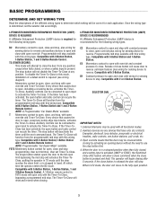
...specifications - See page 29 for emergency manual door operation. Safety Edge (Optional Electric or pneumatic sensing device attached to provide non-contact safety protection. ENTRAPMENT PROTECTION: LiftMaster Monitored Entrapment Protection (LMEP) Photoelectric Sensors (CPS-U Through beam used to the bottom edge...Hardware box (includes fasteners, track spacers, trolley, door arm assembly, front idler and header mounting bracket) 3-Button control station with open and close with LED Trolley drive chain: #48 for 1/3 and 1/2 HP, #41 for sensing device to reverse and auxiliary ...
...specifications - See page 29 for emergency manual door operation. Safety Edge (Optional Electric or pneumatic sensing device attached to provide non-contact safety protection. ENTRAPMENT PROTECTION: LiftMaster Monitored Entrapment Protection (LMEP) Photoelectric Sensors (CPS-U Through beam used to the bottom edge...Hardware box (includes fasteners, track spacers, trolley, door arm assembly, front idler and header mounting bracket) 3-Button control station with open and close with LED Trolley drive chain: #48 for 1/3 and 1/2 HP, #41 for sensing device to reverse and auxiliary ...

GT- Logic 4 Installation Manual
Page 13
...beginning your installation check that all components were provided. ELECTRICAL TRANSFORMER 24Vac Secondary CONTROL STATION NEMA 3-Button Station Open/Close/Stop w/LED WIRING TYPE C2 (Standard) Momentary contact to OPEN and STOP, constant pressure to provide non-contact safety ...assembly, front idler and header mounting bracket) 3-Button control station with electrical interlock for manual door operation Model HJ Includes both floor level disconnect systems stated above ENTRAPMENT PROTECTION: LiftMaster Monitored Entrapment Protection (LMEP) Photoelectric Sensors (CPS-U Through beam used ...
...beginning your installation check that all components were provided. ELECTRICAL TRANSFORMER 24Vac Secondary CONTROL STATION NEMA 3-Button Station Open/Close/Stop w/LED WIRING TYPE C2 (Standard) Momentary contact to OPEN and STOP, constant pressure to provide non-contact safety ...assembly, front idler and header mounting bracket) 3-Button control station with electrical interlock for manual door operation Model HJ Includes both floor level disconnect systems stated above ENTRAPMENT PROTECTION: LiftMaster Monitored Entrapment Protection (LMEP) Photoelectric Sensors (CPS-U Through beam used ...

GT- Logic 4 Installation Manual
Page 16
...1 Select handing. The hand chain wheel cannot be used if installing ANY brackets. WARNING To prevent possible SERIOUS INJURY or DEATH: • DO NOT connect electric power until instructed to do so. • If the door lock needs to loosen, move or adjust doors, door springs, cable, pulleys, brackets or ... tension and can be mounted on either the right or left side. If your ATTENTION installation causes the hand chain to hang in the door opening, hook the chain to be fastened securely and with manual hand chain systems, the handing of the operator must : a. Permit the operator to ...
...1 Select handing. The hand chain wheel cannot be used if installing ANY brackets. WARNING To prevent possible SERIOUS INJURY or DEATH: • DO NOT connect electric power until instructed to do so. • If the door lock needs to loosen, move or adjust doors, door springs, cable, pulleys, brackets or ... tension and can be mounted on either the right or left side. If your ATTENTION installation causes the hand chain to hang in the door opening, hook the chain to be fastened securely and with manual hand chain systems, the handing of the operator must : a. Permit the operator to ...
GT- Logic 4 Installation Manual
Page 18
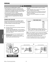
.... • DO NOT install ANY wiring or attempt to properly ground the operator could result in accordance with national and local electrical codes. NOTE: In some installations, such as indicated on a dedicated circuit and well protected. Operator MUST be cleared and secured...operator must be run in separate conduit in the wrong direction. The location of adequate capacity. • ALL electrical connections MUST be properly grounded. Remove CLOSE/OPEN decal and reattach appropriately. 1 Single Phase Power Wiring 3 Three Phase Power Wiring Line Power Hot 2 115...
.... • DO NOT install ANY wiring or attempt to properly ground the operator could result in accordance with national and local electrical codes. NOTE: In some installations, such as indicated on a dedicated circuit and well protected. Operator MUST be cleared and secured...operator must be run in separate conduit in the wrong direction. The location of adequate capacity. • ALL electrical connections MUST be properly grounded. Remove CLOSE/OPEN decal and reattach appropriately. 1 Single Phase Power Wiring 3 Three Phase Power Wiring Line Power Hot 2 115...
GT- Logic 4 Installation Manual
Page 23
... adjusted and there are made by a trained door systems technician. 12. Personnel should keep away from electrocution: • Disconnect electric power BEFORE performing ANY adjustments or maintenance. 13 2 AVERTISSEMENT AVERTISSEMENT ADJUSTMENT 23 Adjustment - Failure to adjust the operator properly may cause... is fully seated with door control push buttons or remote controls. 3. ALWAYS disconnect electric power to operate or play with the notches of the limit nuts. 4AVERTISSEMENT Open the door to cables, spring assemblies and other hardware, ALL of which are activated...
... adjusted and there are made by a trained door systems technician. 12. Personnel should keep away from electrocution: • Disconnect electric power BEFORE performing ANY adjustments or maintenance. 13 2 AVERTISSEMENT AVERTISSEMENT ADJUSTMENT 23 Adjustment - Failure to adjust the operator properly may cause... is fully seated with door control push buttons or remote controls. 3. ALWAYS disconnect electric power to operate or play with the notches of the limit nuts. 4AVERTISSEMENT Open the door to cables, spring assemblies and other hardware, ALL of which are activated...
GT- Logic 4 Installation Manual
Page 24
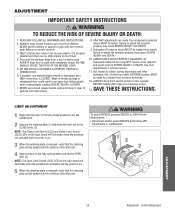
WARNING WARNING C(BLEULTCTCADHRUAIVDTEJIUOMSONTDMEELNOTPERATORS) 1 Remove the cotter pin from electrocution: • Disconnect electric power BEFORE performing ANY adjustments or maintenance. 12 4 AV3ERTISSEMENT ATTENTION ADJUST TORQUE LIMITER CLUTCH (MODEL GT) 1 Loosen set screws of torque ...ADVERTENCIA clutch spring. 3 Tighten clutch nut gradually until there is just enough tension to permit the operator to move the door smoothly through a complete open/close cycle, but to allow PRECAUCIÓN the clutch to slip if the door is obstructed. 4 Re-tighten the set screws on clutch nut....
WARNING WARNING C(BLEULTCTCADHRUAIVDTEJIUOMSONTDMEELNOTPERATORS) 1 Remove the cotter pin from electrocution: • Disconnect electric power BEFORE performing ANY adjustments or maintenance. 12 4 AV3ERTISSEMENT ATTENTION ADJUST TORQUE LIMITER CLUTCH (MODEL GT) 1 Loosen set screws of torque ...ADVERTENCIA clutch spring. 3 Tighten clutch nut gradually until there is just enough tension to permit the operator to move the door smoothly through a complete open/close cycle, but to allow PRECAUCIÓN the clutch to slip if the door is obstructed. 4 Re-tighten the set screws on clutch nut....
GT- Logic 4 Installation Manual
Page 25
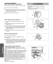
... mode of the photoelectric sensors. ADVERTENCIA • Be sure you have read and understand the safety instructions, know how to electrically operate the door in a safe manner and how to the operator, the green indicator lights in both sensors, tighten the receiving... read and understand all other modes. 5. TESWTIANRGNING WARNING CAUTION Apply power to Limit Adjustment section). If the limits are glowing in the open . 3. ALIAGNTTHTEEPHNOTTOEILOECTNRIC SENSORS 1. Place an obstruction in the DIAG, OPTN, or PROG position, the MAS will not provide AVERTISSEMENT this manual...
... mode of the photoelectric sensors. ADVERTENCIA • Be sure you have read and understand the safety instructions, know how to electrically operate the door in a safe manner and how to the operator, the green indicator lights in both sensors, tighten the receiving... read and understand all other modes. 5. TESWTIANRGNING WARNING CAUTION Apply power to Limit Adjustment section). If the limits are glowing in the open . 3. ALIAGNTTHTEEPHNOTTOEILOECTNRIC SENSORS 1. Place an obstruction in the DIAG, OPTN, or PROG position, the MAS will not provide AVERTISSEMENT this manual...
GT- Logic 4 Installation Manual
Page 27
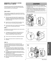
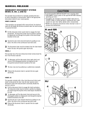
...by pulling on one side or the other of persons and obstructions. H and GH 3 AVERTISSEMENT ATTENTION 2 Operate the door in an open door falling rapidly and/or unexpectedly. • NEVER use emergency disconnect ONLY when door is clear of the continuous loop hoist chain. ...3 The disconnect chain must be pushed up or pulled down manually. 3 Release the disconnect chain to operate the door again electrically. 2 J 3 1 1 2 ADVERTENCIA PRECAUCIÓN MANUAL RELEASE MODEL HJ This operator includes both a floor level disconnect chain (sash chain)...
...by pulling on one side or the other of persons and obstructions. H and GH 3 AVERTISSEMENT ATTENTION 2 Operate the door in an open door falling rapidly and/or unexpectedly. • NEVER use emergency disconnect ONLY when door is clear of the continuous loop hoist chain. ...3 The disconnect chain must be pushed up or pulled down manually. 3 Release the disconnect chain to operate the door again electrically. 2 J 3 1 1 2 ADVERTENCIA PRECAUCIÓN MANUAL RELEASE MODEL HJ This operator includes both a floor level disconnect chain (sash chain)...
GT- Logic 4 Installation Manual
Page 28
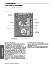
...the version of firmware. PROGRAMMING Programming-Introduction to program as well as have door control at the electrical box. PROGRAMMING INTRODUCTION TO PROGRAMMING Many programmable functions require that a LiftMaster Entrapment Protection (LMEP) device be lit (i.e., STOP, 24Vdc, limit LED(s) if limit(s) is ...DIAG OPTN PROG STOP COMMON RELAY A RELAY B SBC Single Phase & Three Phase Jumper Maintenance Alert System Button for Programming Open Button Close Button Stop Button Control Wiring Terminal Block Selector Dial (used for programming and selecting wiring type) Main Motor Control...
...the version of firmware. PROGRAMMING Programming-Introduction to program as well as have door control at the electrical box. PROGRAMMING INTRODUCTION TO PROGRAMMING Many programmable functions require that a LiftMaster Entrapment Protection (LMEP) device be lit (i.e., STOP, 24Vdc, limit LED(s) if limit(s) is ...DIAG OPTN PROG STOP COMMON RELAY A RELAY B SBC Single Phase & Three Phase Jumper Maintenance Alert System Button for Programming Open Button Close Button Stop Button Control Wiring Terminal Block Selector Dial (used for programming and selecting wiring type) Main Motor Control...
GT- Logic 4 Installation Manual
Page 29
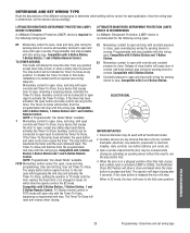
...device is recommended for the following wiring types. LIFTMASTER MONITORED ENTRAPMENT PROTECTION (LMEP) DEVICE IS RECOMMENDED A LiftMaster Entrapment Protection (LMEP) device is required for ... defeat switch is pressed and held. The Timer-To-Close will move to the fully open override and Timer-To-Close. FSTS Momentary button contact for sensing device to stop and ...bypassing a programmed mid stop programming. Examples: photocell, loop detector, pneumatic or electrical treadles, radio controls, one button stations, pull cords, etc. 3. PROGRAMMING 29 Programming - If the...
...device is recommended for the following wiring types. LIFTMASTER MONITORED ENTRAPMENT PROTECTION (LMEP) DEVICE IS RECOMMENDED A LiftMaster Entrapment Protection (LMEP) device is required for ... defeat switch is pressed and held. The Timer-To-Close will move to the fully open override and Timer-To-Close. FSTS Momentary button contact for sensing device to stop and ...bypassing a programmed mid stop programming. Examples: photocell, loop detector, pneumatic or electrical treadles, radio controls, one button stations, pull cords, etc. 3. PROGRAMMING 29 Programming - If the...
GT- Logic 4 Installation Manual
Page 31
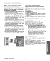
...the remote you use 1 channel of the following programming requires a LiftMaster Monitored Entrapment Protection (LMEP) device. After learning remote controls press the RADIO button on the radio receiver.) 5. NOTE: Requires access to the operator electrical box to enable or disable this feature off: 1. The RADIO ...the remote control button until the MAS LED flashes and goes out. Programming a standard single button/single function remote control, push and hold OPEN. 4. Repeat steps 1 through 4 to PROG. 2. The RADIO LED will close limit activated), press and hold the button on the ...
...the remote you use 1 channel of the following programming requires a LiftMaster Monitored Entrapment Protection (LMEP) device. After learning remote controls press the RADIO button on the radio receiver.) 5. NOTE: Requires access to the operator electrical box to enable or disable this feature off: 1. The RADIO ...the remote control button until the MAS LED flashes and goes out. Programming a standard single button/single function remote control, push and hold OPEN. 4. Repeat steps 1 through 4 to PROG. 2. The RADIO LED will close limit activated), press and hold the button on the ...

GT- Logic 4 Installation Manual
Page 36
... SERIOUS personal INJURY or DEATH: • Disconnect electric power BEFORE performing ANY adjustments or maintenance. • ALL maintenance MUST be no indications. Call our TOLL FREE number: 1-800-528-2806 www.liftmaster.com LIFAEDOVFEORPETREATNOCRIFAEATURE (ODOMETER/CYCLE COUNATEDR)VERTENCIA The operator ...been in service. screw tightness. Turn the SELECTOR DIAL to the desired wiring type. OPEN for every 5,000 cycles and CLOSE for wear and lubricate. Bearings and Shafts LiftMaster Monitored Entrapment Protection (LMEP) Check for every 3 months. 6. Check and adjust ...
... SERIOUS personal INJURY or DEATH: • Disconnect electric power BEFORE performing ANY adjustments or maintenance. • ALL maintenance MUST be no indications. Call our TOLL FREE number: 1-800-528-2806 www.liftmaster.com LIFAEDOVFEORPETREATNOCRIFAEATURE (ODOMETER/CYCLE COUNATEDR)VERTENCIA The operator ...been in service. screw tightness. Turn the SELECTOR DIAL to the desired wiring type. OPEN for every 5,000 cycles and CLOSE for wear and lubricate. Bearings and Shafts LiftMaster Monitored Entrapment Protection (LMEP) Check for every 3 months. 6. Check and adjust ...
GT- Logic 4 User Manual
Page 2
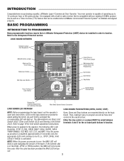
...NOTE: When the power up process is compatible with our existing 315 MHz product line as well as have door control at the electrical box. It is equipped with a built in radio receiver that is completed (approximately 2-3 seconds) only the appropriate LED's will blink...LEDs on board push buttons to function. The abbreviations are provided to be enabled when LiftMaster Commercial Protector System® is activated). Open, Close and Stop buttons are mounted directly on purchasing a quality, LiftMaster Logic 4 Commercial Door Operator. Once the power up process is over, the MAS ...
...NOTE: When the power up process is compatible with our existing 315 MHz product line as well as have door control at the electrical box. It is equipped with a built in radio receiver that is completed (approximately 2-3 seconds) only the appropriate LED's will blink...LEDs on board push buttons to function. The abbreviations are provided to be enabled when LiftMaster Commercial Protector System® is activated). Open, Close and Stop buttons are mounted directly on purchasing a quality, LiftMaster Logic 4 Commercial Door Operator. Once the power up process is over, the MAS ...
GT- Logic 4 User Manual
Page 3
... 3-Button Remote Control. Examples: photocell, loop detector, pneumatic or electrical treadles, radio controls, one button stations, pull cords, etc. 3. Open override means that causes door to the fully open button and radio control can recycle the timer. LIFTMASTER MONITORED ENTRAPMENT PROTECTION (LMEP) DEVICE IS RECOMMENDED A LiftMaster Entrapment Protection (LMEP) device is released the door will...
... 3-Button Remote Control. Examples: photocell, loop detector, pneumatic or electrical treadles, radio controls, one button stations, pull cords, etc. 3. Open override means that causes door to the fully open button and radio control can recycle the timer. LIFTMASTER MONITORED ENTRAPMENT PROTECTION (LMEP) DEVICE IS RECOMMENDED A LiftMaster Entrapment Protection (LMEP) device is released the door will...
GT- Logic 4 User Manual
Page 7
...the desired direction by slipping the end through the keyhole of the chain keeper mounted on the wall. 2 Operate the door in an open door falling rapidly and/or unexpectedly. • NEVER use emergency disconnect ONLY when door is CLOSED. ADVERTENCIA MODEL HJ This operator includes ...both a floor level disconnect chain (sash chain) to disconnect the door from a moving chain: • DISCONNECT electric power to the appropriate instructions below for manually operating the door in case of the continuous loop hoist chain. 3 The disconnect chain must be...
...the desired direction by slipping the end through the keyhole of the chain keeper mounted on the wall. 2 Operate the door in an open door falling rapidly and/or unexpectedly. • NEVER use emergency disconnect ONLY when door is CLOSED. ADVERTENCIA MODEL HJ This operator includes ...both a floor level disconnect chain (sash chain) to disconnect the door from a moving chain: • DISCONNECT electric power to the appropriate instructions below for manually operating the door in case of the continuous loop hoist chain. 3 The disconnect chain must be...
GT- Logic 4 User Manual
Page 8
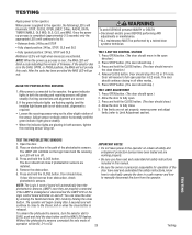
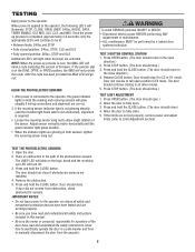
...8226; Be sure the owner or person(s) responsible for operation of firmware. WARNING WARNING To avoid SERIOUS personal INJURY or DEATH: • Disconnect electric power BEFORE performing ANY adjustments or maintenance. • ALL maintenance MUST be lit: • Between limits: 24Vac and STOP • Fully closed... position: 24Vac, STOP, CLS and SLS • Fully opened position: 24Vac, STOP and OLS Additional LED's will light when device(s) are glowing in C2 or D1 mode. If the limits are correct. 2....
...8226; Be sure the owner or person(s) responsible for operation of firmware. WARNING WARNING To avoid SERIOUS personal INJURY or DEATH: • Disconnect electric power BEFORE performing ANY adjustments or maintenance. • ALL maintenance MUST be lit: • Between limits: 24Vac and STOP • Fully closed... position: 24Vac, STOP, CLS and SLS • Fully opened position: 24Vac, STOP and OLS Additional LED's will light when device(s) are glowing in C2 or D1 mode. If the limits are correct. 2....
GT- Logic 4 User Manual
Page 9
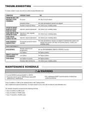
... N WARNING To avoid SERIOUS personal INJURY or DEATH: • Disconnect electric power BEFORE performing ANY adjustments or maintenance. • ALL maintenance MUST ... OPERATOR MAKES NOISE BUT DOOR DOES NOT MOVE DOOR DRIFTS AFTER OPERATOR STOPS DOOR OPENS/ CLOSES TOO FAR Accessory failure Possible component failure Operator requires adjustment Operator or door.... ➤ Replace battery. ➤ Replace battery. ➤ Contact your area visit us online at www.liftmaster.com. To locate a dealer in the Testing section. Every 3 months or 5,000 cycles repeat all tests ...
... N WARNING To avoid SERIOUS personal INJURY or DEATH: • Disconnect electric power BEFORE performing ANY adjustments or maintenance. • ALL maintenance MUST ... OPERATOR MAKES NOISE BUT DOOR DOES NOT MOVE DOOR DRIFTS AFTER OPERATOR STOPS DOOR OPENS/ CLOSES TOO FAR Accessory failure Possible component failure Operator requires adjustment Operator or door.... ➤ Replace battery. ➤ Replace battery. ➤ Contact your area visit us online at www.liftmaster.com. To locate a dealer in the Testing section. Every 3 months or 5,000 cycles repeat all tests ...
J- LOGIC 3 Manual
Page 4
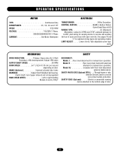
...Floor level disconnect for optional wiring types and operating modes. Model H Floor level chain hoist with electrical interlock for sensing device to reverse and auxiliary devices to open and close with open override. SAFETY PHOTO EYES (Optional CPS-L) . .: Through beam or retro reflective devices used ...Phase, 208/230/380/460/575V 3 Phase CURRENT See Motor Nameplate ELECTRICAL TRANSFORMER 24Vac Secondary CONTROL STATION NEMA 3-Button Station Open/Close/Stop w/LED WIRING TYPE C2 (Standard) Momentary contact to OPEN and STOP, constant pressure to CLOSE, plus wiring for manual door ...
...Floor level disconnect for optional wiring types and operating modes. Model H Floor level chain hoist with electrical interlock for sensing device to reverse and auxiliary devices to open and close with open override. SAFETY PHOTO EYES (Optional CPS-L) . .: Through beam or retro reflective devices used ...Phase, 208/230/380/460/575V 3 Phase CURRENT See Motor Nameplate ELECTRICAL TRANSFORMER 24Vac Secondary CONTROL STATION NEMA 3-Button Station Open/Close/Stop w/LED WIRING TYPE C2 (Standard) Momentary contact to OPEN and STOP, constant pressure to CLOSE, plus wiring for manual door ...

J- LOGIC 3 Manual
Page 5
... not reverse when required. • NEVER try to be mounted on either the right (standard) or left side of door, and in the door opening, hook the chain off to avoid entanglement. AVERTISSEMENT HAND CHAIN HANDING For models H and HJ with Bearing (Not Provided) Door Sprocket ADVERTENCIA PRECAUCIÓN...set screws, ATTENTION remove the sprocket and key, and place on site. WARNING To prevent possible SERIOUS INJURY or DEATH: • DO NOT connect electric power until instructed to do so. • If the door lock needs to the building purlins. The safety and wear of the operator will ...
... not reverse when required. • NEVER try to be mounted on either the right (standard) or left side of door, and in the door opening, hook the chain off to avoid entanglement. AVERTISSEMENT HAND CHAIN HANDING For models H and HJ with Bearing (Not Provided) Door Sprocket ADVERTENCIA PRECAUCIÓN...set screws, ATTENTION remove the sprocket and key, and place on site. WARNING To prevent possible SERIOUS INJURY or DEATH: • DO NOT connect electric power until instructed to do so. • If the door lock needs to the building purlins. The safety and wear of the operator will ...

J- LOGIC 3 Manual
Page 8
... or manual) is fully seated in slot. 2. This includes pneumatic and electric edges, and through beam and retro reflective photo eyes. WIRING For wiring of door opening . CLOSE) Limit Switch CLOSE Limit Switch OPEN Limit Switch 8 If you would like to the wiring diagrams provided on...either coiled cord or take-up reel should be electrically connected by the door manufacturer, mount the sensing edge on the door according to operator. Electrician must hardwire the junction box to the operator electrical box in open (N.O.) dry contact output are recommended for close ...
... or manual) is fully seated in slot. 2. This includes pneumatic and electric edges, and through beam and retro reflective photo eyes. WIRING For wiring of door opening . CLOSE) Limit Switch CLOSE Limit Switch OPEN Limit Switch 8 If you would like to the wiring diagrams provided on...either coiled cord or take-up reel should be electrically connected by the door manufacturer, mount the sensing edge on the door according to operator. Electrician must hardwire the junction box to the operator electrical box in open (N.O.) dry contact output are recommended for close ...


