
GT- Logic 4 Installation Manual
Page 2
... the Manual Disconnect 17 WIRING 18-19 Power and Ground 18 Control Station 19 ENTRAPMENT PROTECTION 20-22 LiftMaster Monitored Entrapment Protection (LMEP 20 Install the Photoelectric Sensors (Provided 21 Mount the Photoelectric Sensors (Provided 22 Wire the...Disconnect System Model GT and T 26 Emergency Disconnect System Model APT 26 Emergency Disconnect System Model H, GH, J, and HJ 27 PROGRAMMING 28-35 Introduction to Order Repair Parts 36 TROUBLESHOOTING 37-40 Diagnostic Chart 37 Troubleshooting Guide 38 Troubleshooting Error Codes 39 Troubleshooting Radio ...
... the Manual Disconnect 17 WIRING 18-19 Power and Ground 18 Control Station 19 ENTRAPMENT PROTECTION 20-22 LiftMaster Monitored Entrapment Protection (LMEP 20 Install the Photoelectric Sensors (Provided 21 Mount the Photoelectric Sensors (Provided 22 Wire the...Disconnect System Model GT and T 26 Emergency Disconnect System Model APT 26 Emergency Disconnect System Model H, GH, J, and HJ 27 PROGRAMMING 28-35 Introduction to Order Repair Parts 36 TROUBLESHOOTING 37-40 Diagnostic Chart 37 Troubleshooting Guide 38 Troubleshooting Error Codes 39 Troubleshooting Radio ...
GT- Logic 4 Installation Manual
Page 24
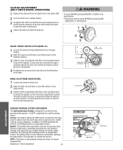
.... Back off torque nut until there is very little tension on models GH and GT.) NOTE: This feature is automatically learned and does not require programming. It is NOT a substitute for a centrifugal switch on single phase motors. Adjustment - Clutch adjustment 24 LOSE OPEN RPM Sensor Logic Board In addition, the RPM...
.... Back off torque nut until there is very little tension on models GH and GT.) NOTE: This feature is automatically learned and does not require programming. It is NOT a substitute for a centrifugal switch on single phase motors. Adjustment - Clutch adjustment 24 LOSE OPEN RPM Sensor Logic Board In addition, the RPM...
GT- Logic 4 Installation Manual
Page 28
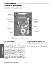
... limit(s) is applied to the Entrapment Protection section. The abbreviations are provided to program as well as have door control at the electrical box. Refer to programming 28 PROGRAMMING Programming-Introduction to page 19 for limit switch adjustment instructions. When power is activated). ... board are Open Limit Switch (OLS), Close Limit Switch (CLS) and Sensing Limit Switch (SLS). PROGRAMMING INTRODUCTION TO PROGRAMMING Many programmable functions require that a LiftMaster Entrapment Protection (LMEP) device be installed in the DIAG, OPTN, or PROG position, the MAS will...
... limit(s) is applied to the Entrapment Protection section. The abbreviations are provided to program as well as have door control at the electrical box. Refer to programming 28 PROGRAMMING Programming-Introduction to page 19 for limit switch adjustment instructions. When power is activated). ... board are Open Limit Switch (OLS), Close Limit Switch (CLS) and Sensing Limit Switch (SLS). PROGRAMMING INTRODUCTION TO PROGRAMMING Many programmable functions require that a LiftMaster Entrapment Protection (LMEP) device be installed in the DIAG, OPTN, or PROG position, the MAS will...
GT- Logic 4 Installation Manual
Page 29
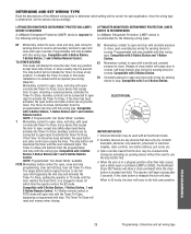
...for sensing device to open, close . SELECTOR DIAL T E2 D1 C2 B2 TS FSTS DIAG OPTN PROG IMPORTANT NOTES: 1. PROGRAMMING 29 Programming - Momentary contact to stop button first. 4. If the timer has been activated, the open override and Timer-To-Close. ... 3-Button Station. Every device that causes door to reverse. The stop available with this wiring type. LIFTMASTER MONITORED ENTRAPMENT PROTECTION (LMEP) DEVICE IS RECOMMENDED A LiftMaster Entrapment Protection (LMEP) device is recommended for sensing device to open position. Auxiliary controls can recycle the...
...for sensing device to open, close . SELECTOR DIAL T E2 D1 C2 B2 TS FSTS DIAG OPTN PROG IMPORTANT NOTES: 1. PROGRAMMING 29 Programming - Momentary contact to stop button first. 4. If the timer has been activated, the open override and Timer-To-Close. ... 3-Button Station. Every device that causes door to reverse. The stop available with this wiring type. LIFTMASTER MONITORED ENTRAPMENT PROTECTION (LMEP) DEVICE IS RECOMMENDED A LiftMaster Entrapment Protection (LMEP) device is recommended for sensing device to open position. Auxiliary controls can recycle the...
GT- Logic 4 Installation Manual
Page 30
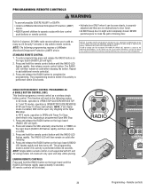
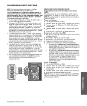
... to operate or play with Timer-To-Close start /refresh. To enter programming press and release the RADIO button on the logic board (RADIO LED will work in the following programming requires a LiftMaster Monitored Entrapment Protection (LMEP) device. Repeat to add as many as a...keep door in 3-channel, 315 MHz radio receiver allows you to add additional remote control(s). PROGRAMMING REMOTE CONTROLS WARNING To prevent possible SEVERE INJURY or DEATH: CAUTION • Install a LiftMaster Monitored Entrapment Protection (LMEP) • Activate door ONLY when it can be erased. The...
... to operate or play with Timer-To-Close start /refresh. To enter programming press and release the RADIO button on the logic board (RADIO LED will work in the following programming requires a LiftMaster Monitored Entrapment Protection (LMEP) device. Repeat to add as many as a...keep door in 3-channel, 315 MHz radio receiver allows you to add additional remote control(s). PROGRAMMING REMOTE CONTROLS WARNING To prevent possible SEVERE INJURY or DEATH: CAUTION • Install a LiftMaster Monitored Entrapment Protection (LMEP) • Activate door ONLY when it can be erased. The...
GT- Logic 4 Installation Manual
Page 31
... fully closed position (close the door, and the third button will flash, this confirms that the remote control has been programmed. (By programming the remote you use 1 channel of the following programming requires a LiftMaster Monitored Entrapment Protection (LMEP) device. While holding STOP and CLOSE, press and hold the remote control button until the MAS...
... fully closed position (close the door, and the third button will flash, this confirms that the remote control has been programmed. (By programming the remote you use 1 channel of the following programming requires a LiftMaster Monitored Entrapment Protection (LMEP) device. While holding STOP and CLOSE, press and hold the remote control button until the MAS...
GT- Logic 4 Installation Manual
Page 32
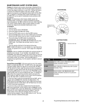
...DIAGNOSTIC and press the MAS button. SELECTOR DIAL T E2 D1 C2 B2 TS FSTS DIAG OPTN PROG Operation will flash back the programmed settings. To Program: 1. Turn the selector dial to the desired wiring type. The on board LED will vary depending on the logic board is due... elapsed. Press the OPEN button once for every 3 month increments. 6. Every time the operator leaves the close limit is installed with its current programmed value. Benefit: The Maintenance Alert System (MAS) assists the installing dealer in a row followed by a pause, an operator error occurred. the ...
...DIAGNOSTIC and press the MAS button. SELECTOR DIAL T E2 D1 C2 B2 TS FSTS DIAG OPTN PROG Operation will flash back the programmed settings. To Program: 1. Turn the selector dial to the desired wiring type. The on board LED will vary depending on the logic board is due... elapsed. Press the OPEN button once for every 3 month increments. 6. Every time the operator leaves the close limit is installed with its current programmed value. Benefit: The Maintenance Alert System (MAS) assists the installing dealer in a row followed by a pause, an operator error occurred. the ...
GT- Logic 4 Installation Manual
Page 33
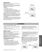
...wiring type T E2 D1 C2 B2 TS FSTS DIAG OPTN PROG WARNING To prevent possible SEVERE INJURY or DEATH: CAUTION • Install a LiftMaster Monitored Entrapment Protection (LMEP) device. • Activate door ONLY when it can be unobstructed. SELECTOR DIAL T E2 D1 C2 B2 TS FSTS...mid stop height, then press and release the STOP button. 5. To Program: 1. Press the OPEN button, wait until completely closed. Close the door. 2. Press and release the CLOSE button for 10 seconds. Once at least one LiftMaster Monitored (TS ,T or FSTS). The MID LED will flash to ...
...wiring type T E2 D1 C2 B2 TS FSTS DIAG OPTN PROG WARNING To prevent possible SEVERE INJURY or DEATH: CAUTION • Install a LiftMaster Monitored Entrapment Protection (LMEP) device. • Activate door ONLY when it can be unobstructed. SELECTOR DIAL T E2 D1 C2 B2 TS FSTS...mid stop height, then press and release the STOP button. 5. To Program: 1. Press the OPEN button, wait until completely closed. Close the door. 2. Press and release the CLOSE button for 10 seconds. Once at least one LiftMaster Monitored (TS ,T or FSTS). The MID LED will flash to ...
GT- Logic 4 Installation Manual
Page 34
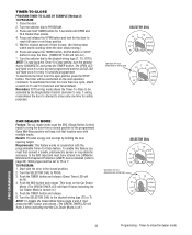
...sensor or loop detector accessory to bring the door from the open or mid stop watch starts counting when the door stops moving.) 6. TO PROGRAM: 1. Push the TIMER button and release. 6. Press and release the TIMER button, CLOSE button or STOP button to stop the timer. (...-To-Close feature. Push the MID button and release. Timer-to-close only one LiftMaster Monitored Entrapment Protection (LMEP) device installed (refer to TS or T. Press and hold TIMER button for every 15 seconds programmed. Close the door. 2. Benefit: Provides energy cost savings by the Single Button Control...
...sensor or loop detector accessory to bring the door from the open or mid stop watch starts counting when the door stops moving.) 6. TO PROGRAM: 1. Push the TIMER button and release. 6. Press and release the TIMER button, CLOSE button or STOP button to stop the timer. (...-To-Close feature. Push the MID button and release. Timer-to-close only one LiftMaster Monitored Entrapment Protection (LMEP) device installed (refer to TS or T. Press and hold TIMER button for every 15 seconds programmed. Close the door. 2. Benefit: Provides energy cost savings by the Single Button Control...
GT- Logic 4 Installation Manual
Page 35
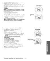
...) Feature: The operator can learn the time it will vary depending on wiring type T E2 D1 C2 B2 TS FSTS DIAG OPTN PROG PROGRAMMING Programming - Turn the selector dial to open limit. 5. Set the selector dial to the desired wiring type. Car Dealer Mode is deactivated c. ... The MAS LED will be manually learned for 5 seconds. Return the selector dial to PROGRAM. 3. Press the OPEN button and wait for the MRT is set time it takes to DIAGNOSTIC. 2. The LiftMaster Monitored Entrapment Protection (LMEP) device will flash momentarily when the factory defaults have been restored...
...) Feature: The operator can learn the time it will vary depending on wiring type T E2 D1 C2 B2 TS FSTS DIAG OPTN PROG PROGRAMMING Programming - Turn the selector dial to open limit. 5. Set the selector dial to the desired wiring type. Car Dealer Mode is deactivated c. ... The MAS LED will be manually learned for 5 seconds. Return the selector dial to PROGRAM. 3. Press the OPEN button and wait for the MRT is set time it takes to DIAGNOSTIC. 2. The LiftMaster Monitored Entrapment Protection (LMEP) device will flash momentarily when the factory defaults have been restored...
GT- Logic 4 Installation Manual
Page 37
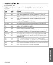
.../CLOSE button is pressed. Indicates the Maintenance Alert System has been activated or an error code has been triggered. LED turns on indicates TIMER is programmed and will not close after preset time. Indicates communication between common and terminal 8. The following chart should assist in the installation and troubleshooting of the...
.../CLOSE button is pressed. Indicates the Maintenance Alert System has been activated or an error code has been triggered. LED turns on indicates TIMER is programmed and will not close after preset time. Indicates communication between common and terminal 8. The following chart should assist in the installation and troubleshooting of the...

GT- Logic 4 Installation Manual
Page 38
...NOT RESPOND TO ANY COMMANDS POSSIBLE CAUSE FIX a) No power supply b) Operator control station is wired wrong c) Interlock switch is activated d) Dial still in programming, option, or diagnostic mode e) Motor is malfunctioning f) Motor thermal overload tripped g) Possible accessory malfunction h) Off Board relay may need to be replaced ...one at a time testing for continuity. If Relay A or B lights and the door does not move, off board relay may need to program. THE DOOR WILL OPEN SOME BUT NOT COMPLETELY. THE DOOR WILL MOVE The Maximum Run Timer is hot. Clear the Mid Stop by using ...
...NOT RESPOND TO ANY COMMANDS POSSIBLE CAUSE FIX a) No power supply b) Operator control station is wired wrong c) Interlock switch is activated d) Dial still in programming, option, or diagnostic mode e) Motor is malfunctioning f) Motor thermal overload tripped g) Possible accessory malfunction h) Off Board relay may need to be replaced ...one at a time testing for continuity. If Relay A or B lights and the door does not move, off board relay may need to program. THE DOOR WILL OPEN SOME BUT NOT COMPLETELY. THE DOOR WILL MOVE The Maximum Run Timer is hot. Clear the Mid Stop by using ...

GT- Logic 4 Installation Manual
Page 39
... take priority over normal MAS LED operation. TROUBLESHOOTING ERROR CODES Logic 4.0 operators incorporate a self diagnostic feature built into option card receptacles LiftMaster Monitored Entrapment Protection (LMEP) device faulted or removed for list of Motor movement at a time. Check AC line for any faults ... change 1. Check transformer secondary for the error to OPEN position Cleared by a pause, an operator error has occurred. Enter programming mode and move the door with the operator. There may be recognized as enough power is present Operator will continue to function...
... take priority over normal MAS LED operation. TROUBLESHOOTING ERROR CODES Logic 4.0 operators incorporate a self diagnostic feature built into option card receptacles LiftMaster Monitored Entrapment Protection (LMEP) device faulted or removed for list of Motor movement at a time. Check AC line for any faults ... change 1. Check transformer secondary for the error to OPEN position Cleared by a pause, an operator error has occurred. Enter programming mode and move the door with the operator. There may be recognized as enough power is present Operator will continue to function...
GT- Logic 4 User Manual
Page 2
...process is in order to be wired between terminals 4 and 5 for the on the logic board. Refer to program as well as a Timer-to-Close (TTC) feature that a LiftMaster Entrapment Protection (LMEP) device be installed in the DIAG, OPTN, or PROG position, the MAS will go out.... OVERVIEW LOGIC BOARD PUSH BUTTONS (OPEN, CLOSE, STOP) NOTE: Before programming the logic board, set the operator's open and close limits. Thus, making it easy to the Entrapment Protection section. LEDs on purchasing a quality, LiftMaster Logic 4 Commercial Door Operator. It is equipped with a built in...
...process is in order to be wired between terminals 4 and 5 for the on the logic board. Refer to program as well as a Timer-to-Close (TTC) feature that a LiftMaster Entrapment Protection (LMEP) device be installed in the DIAG, OPTN, or PROG position, the MAS will go out.... OVERVIEW LOGIC BOARD PUSH BUTTONS (OPEN, CLOSE, STOP) NOTE: Before programming the logic board, set the operator's open and close limits. Thus, making it easy to the Entrapment Protection section. LEDs on purchasing a quality, LiftMaster Logic 4 Commercial Door Operator. It is equipped with a built in...
GT- Logic 4 User Manual
Page 3
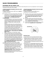
...User set Timer-To-Close. Compatible with 2 or 3-Button Station. Release of the different wiring types to open , close and stop programming. Compatible with 3-Button Station, 1-Button Station, 1 and 3-Button Remote Control. Examples: photocell, loop detector, pneumatic or electrical treadles, ... limit, or is required for open , close button is determined, set the selector dial accordingly. LIFTMASTER MONITORED ENTRAPMENT PROTECTION (LMEP) DEVICE IS REQUIRED A LiftMaster Entrapment Protection (LMEP) device is stopped in TS mode until the next command input. The stop ...
...User set Timer-To-Close. Compatible with 2 or 3-Button Station. Release of the different wiring types to open , close and stop programming. Compatible with 3-Button Station, 1-Button Station, 1 and 3-Button Remote Control. Examples: photocell, loop detector, pneumatic or electrical treadles, ... limit, or is required for open , close button is determined, set the selector dial accordingly. LIFTMASTER MONITORED ENTRAPMENT PROTECTION (LMEP) DEVICE IS REQUIRED A LiftMaster Entrapment Protection (LMEP) device is stopped in TS mode until the next command input. The stop ...
GT- Logic 4 User Manual
Page 4
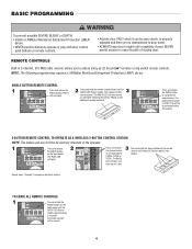
... remote controls T E2 TS FSTS will flash and then stay on the logic board (OPEN, CLOSE or STOP). BASIC PROGRAMMING WARNING To prevent possible SEVERE INJURY or DEATH: CAUTION • Install a LiftMaster Monitored Entrapment Protection (LMEP) device. • Activate door ONLY when it can be erased. 4 AD A AVE AV 3-BUTTON REMOTE...
... remote controls T E2 TS FSTS will flash and then stay on the logic board (OPEN, CLOSE or STOP). BASIC PROGRAMMING WARNING To prevent possible SEVERE INJURY or DEATH: CAUTION • Install a LiftMaster Monitored Entrapment Protection (LMEP) device. • Activate door ONLY when it can be erased. 4 AD A AVE AV 3-BUTTON REMOTE...
GT- Logic 4 User Manual
Page 5
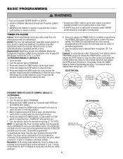
...LEDs will flash to Wiring type must be seen clearly, is properly device. AV 4. BASIC PROGRAMMING WARNING W To prevent possible SEVERE INJURY or DEATH: CAUTION • Install a LiftMaster Monitored Entrapment Protection (LMEP) • Activate door ONLY when it can be unobstructed. Turn ...after preset time. Reminders: FSTS wiring mode allows the Timer-To-Close to be set to close only one LiftMaster Monitored FSTS). Turn the selector dial to PROGRAM. 3. Press and release the OPEN button for every second the operator should wait before attempting to TS, ...
...LEDs will flash to Wiring type must be seen clearly, is properly device. AV 4. BASIC PROGRAMMING WARNING W To prevent possible SEVERE INJURY or DEATH: CAUTION • Install a LiftMaster Monitored Entrapment Protection (LMEP) • Activate door ONLY when it can be unobstructed. Turn ...after preset time. Reminders: FSTS wiring mode allows the Timer-To-Close to be set to close only one LiftMaster Monitored FSTS). Turn the selector dial to PROGRAM. 3. Press and release the OPEN button for every second the operator should wait before attempting to TS, ...
GT- Logic 4 User Manual
Page 9
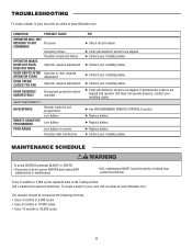
...or DEATH: • Disconnect electric power BEFORE performing ANY adjustments or maintenance. • ALL maintenance MUST be serviced at www.liftmaster.com. Every 3 months or 5,000 cycles repeat all tests in the Testing section. To locate a dealer in your installing... installing dealer. ➤ Verify photoelectric sensors are aligned and operator still does not operate properly, contact your installing dealer. ➤ See PROGRAMMING REMOTE CONTROLS section. ➤ Replace battery. ➤ Replace battery. ➤ Replace battery. ➤ Contact your area visit us online...
...or DEATH: • Disconnect electric power BEFORE performing ANY adjustments or maintenance. • ALL maintenance MUST be serviced at www.liftmaster.com. Every 3 months or 5,000 cycles repeat all tests in the Testing section. To locate a dealer in your installing... installing dealer. ➤ Verify photoelectric sensors are aligned and operator still does not operate properly, contact your installing dealer. ➤ See PROGRAMMING REMOTE CONTROLS section. ➤ Replace battery. ➤ Replace battery. ➤ Replace battery. ➤ Contact your area visit us online...
J- LOGIC 3 Manual
Page 2
...the possibility of Operator Feature 25 How to Close 21-22 Car Dealer Mode 22 AUTOMATICALLY LEARNED PROGRAMMING Auxiliary Reversal System/RPM Sensor 23 Maximum Run Timer (MRT 23 OPTIONAL PROGRAMMING Red/Green Warning Light Card 24 Resetting Factory Defaults - Clearing Memory 24 MAINTENANCE Maintenance Schedule ...11 DIAGRAMS Standard Power & Control Connection Diagrams 12 1 Phase Wiring Diagram 13 3 Phase Wiring Diagram 14 Logic Board 15 PROGRAMMING Logic Control Pushbuttons 16 Determine and Set Wiring Type 16 Failsafe Wiring Types 17 Self-Monitoring Safety Device Options 17...
...the possibility of Operator Feature 25 How to Close 21-22 Car Dealer Mode 22 AUTOMATICALLY LEARNED PROGRAMMING Auxiliary Reversal System/RPM Sensor 23 Maximum Run Timer (MRT 23 OPTIONAL PROGRAMMING Red/Green Warning Light Card 24 Resetting Factory Defaults - Clearing Memory 24 MAINTENANCE Maintenance Schedule ...11 DIAGRAMS Standard Power & Control Connection Diagrams 12 1 Phase Wiring Diagram 13 3 Phase Wiring Diagram 14 Logic Board 15 PROGRAMMING Logic Control Pushbuttons 16 Determine and Set Wiring Type 16 Failsafe Wiring Types 17 Self-Monitoring Safety Device Options 17...

J- LOGIC 3 Manual
Page 15
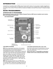
LOGIC BOARD Auxiliary Board Connections Programmed Chip Maximum Run Timer Button Radio Learn Button Mid Stop Learn Button Timer to Close Learn Button R31 U7 D8 U1 Ø14LGØ657-A &#... 9 EDGE 8 OPEN 7 CLOSE 6 STOP 5 CMN 4 3 2 SBC 1 F1 C54 C71 C78 ® Motor Direction Jumper Single Phase and Three Phase Jumper Maintenance Alert System Button for Programming Open Button Close Button Stop Button Control Wiring Terminal Block Wiring Type Selector Dial Failsafe Switch 15
LOGIC BOARD Auxiliary Board Connections Programmed Chip Maximum Run Timer Button Radio Learn Button Mid Stop Learn Button Timer to Close Learn Button R31 U7 D8 U1 Ø14LGØ657-A &#... 9 EDGE 8 OPEN 7 CLOSE 6 STOP 5 CMN 4 3 2 SBC 1 F1 C54 C71 C78 ® Motor Direction Jumper Single Phase and Three Phase Jumper Maintenance Alert System Button for Programming Open Button Close Button Stop Button Control Wiring Terminal Block Wiring Type Selector Dial Failsafe Switch 15


