

GT- Logic 4 Installation Manual
Page 4
... attached to 24 feet. LIMIT ADJUST Linear driven, fully adjustable screw type cams. Adjustable to the bottom edge of door. OPERATOR SPECIFICATIONS MOTOR TYPE Continuous duty HORSEPOWER: Model APT 1/2 HP Model GT 1/2, 3/4, 1 and 1-1/2 HP Model T 1/3, 1/2, 3/4 and 1 HP...front idler and header mounting bracket) 3-Button control station with open override. Carton inventory/Operator specifications - ENTRAPMENT PROTECTION: LiftMaster Monitored Entrapment Protection (LMEP) Photoelectric Sensors (CPS-U Through beam used to open and close with LED Trolley drive chain: #48...
... attached to 24 feet. LIMIT ADJUST Linear driven, fully adjustable screw type cams. Adjustable to the bottom edge of door. OPERATOR SPECIFICATIONS MOTOR TYPE Continuous duty HORSEPOWER: Model APT 1/2 HP Model GT 1/2, 3/4, 1 and 1-1/2 HP Model T 1/3, 1/2, 3/4 and 1 HP...front idler and header mounting bracket) 3-Button control station with open override. Carton inventory/Operator specifications - ENTRAPMENT PROTECTION: LiftMaster Monitored Entrapment Protection (LMEP) Photoelectric Sensors (CPS-U Through beam used to open and close with LED Trolley drive chain: #48...

GT- Logic 4 Installation Manual
Page 13
...plus wiring for manual door operation Model HJ Includes both floor level disconnect systems stated above ENTRAPMENT PROTECTION: LiftMaster Monitored Entrapment Protection (LMEP) Photoelectric Sensors (CPS-U Through beam used to open and close with LED Hoist hand chain (...CPS-U photoelectric sensors (standard) OPERATOR SPECIFICATIONS MOTOR TYPE Continuous duty HORSEPOWER: Model J, H and HJ 1/3, 1/2, 3/4 and 1 HP Model GH 1/2, 3/4, 1, 1-1/2, 2 and 3 HP SPEED 1725 RPM VOLTAGE: Model J, H and HJ 115/230V 1 Phase 208/230/460/575V 3 Phase Model GH 115/230V 1 Phase 208/230/460/575V...
...plus wiring for manual door operation Model HJ Includes both floor level disconnect systems stated above ENTRAPMENT PROTECTION: LiftMaster Monitored Entrapment Protection (LMEP) Photoelectric Sensors (CPS-U Through beam used to open and close with LED Hoist hand chain (...CPS-U photoelectric sensors (standard) OPERATOR SPECIFICATIONS MOTOR TYPE Continuous duty HORSEPOWER: Model J, H and HJ 1/3, 1/2, 3/4 and 1 HP Model GH 1/2, 3/4, 1, 1-1/2, 2 and 3 HP SPEED 1725 RPM VOLTAGE: Model J, H and HJ 115/230V 1 Phase 208/230/460/575V 3 Phase Model GH 115/230V 1 Phase 208/230/460/575V...
GT- Logic 4 Installation Manual
Page 18
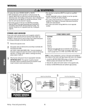
...-out the power. The operator should be on a dedicated circuit and well protected. When a larger wire gauge is 12 AWG. Locate the MOTOR DIRECTION jumper on the electrical box labels. 1 Remove the operator cover. 2 Run power wires to electrical box according to properly ground the operator...Disconnect power at that can be connected to the operator's terminal is required, the wire must be gauged down to appropriate terminals. To change motor rotation, exchange incoming power leads L1 and L2. 3 Attach power and ground wires to 12 AWG. Power and ground wiring 18 Remove CLOSE...
...-out the power. The operator should be on a dedicated circuit and well protected. When a larger wire gauge is 12 AWG. Locate the MOTOR DIRECTION jumper on the electrical box labels. 1 Remove the operator cover. 2 Run power wires to electrical box according to properly ground the operator...Disconnect power at that can be connected to the operator's terminal is required, the wire must be gauged down to appropriate terminals. To change motor rotation, exchange incoming power leads L1 and L2. 3 Attach power and ground wires to 12 AWG. Power and ground wiring 18 Remove CLOSE...
GT- Logic 4 Installation Manual
Page 24
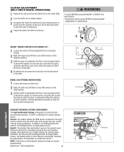
...protection. In addition, the RPM eliminates the need for a safety sensing device. It is designed to protect the door and motorized operator. Benefit: The Auxiliary Reversal System reverses the operator upon hitting an obstruction, preventing excessive door and operator damage. Clutch...allow the clutch to slip if the door is obstructed. Adjustment - We require the use of motor failures is eliminated. (Auxiliary Reversal System not applicable on models GH and GT.) NOTE: This feature is automatically learned and does not require programming. WARNING WARNING C(...
...protection. In addition, the RPM eliminates the need for a safety sensing device. It is designed to protect the door and motorized operator. Benefit: The Auxiliary Reversal System reverses the operator upon hitting an obstruction, preventing excessive door and operator damage. Clutch...allow the clutch to slip if the door is obstructed. Adjustment - We require the use of motor failures is eliminated. (Auxiliary Reversal System not applicable on models GH and GT.) NOTE: This feature is automatically learned and does not require programming. WARNING WARNING C(...
GT- Logic 4 Installation Manual
Page 28
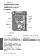
...terminals 4 and 5 for the on the logic board. PROGRAMMING Programming-Introduction to page 19 for programming and selecting wiring type) Main Motor Control Harness Connection LOGIC BOARD LED OVERVIEW NOTE: Before programming the logic board, set the operator's open and close limits. The ... buttons to program as well as have door control at the electrical box. PROGRAMMING INTRODUCTION TO PROGRAMMING Many programmable functions require that a LiftMaster Entrapment Protection (LMEP) device be installed in the DIAG, OPTN, or PROG position, the MAS will light up. If the selector...
...terminals 4 and 5 for the on the logic board. PROGRAMMING Programming-Introduction to page 19 for programming and selecting wiring type) Main Motor Control Harness Connection LOGIC BOARD LED OVERVIEW NOTE: Before programming the logic board, set the operator's open and close limits. The ... buttons to program as well as have door control at the electrical box. PROGRAMMING INTRODUCTION TO PROGRAMMING Many programmable functions require that a LiftMaster Entrapment Protection (LMEP) device be installed in the DIAG, OPTN, or PROG position, the MAS will light up. If the selector...
GT- Logic 4 Installation Manual
Page 30
...be open and stop while opening. W W Built in 3-channel, 315 MHz radio receiver allows you to the following programming requires a LiftMaster Monitored Entrapment Protection (LMEP) device. Operation is performed within 30 seconds. AVERTISSEMENT 2. Repeat to complete the programming. RADIO 1. The programming ... single button control. adjusted and there are prohibited, except for changing the code setting or replacing the battery. SLOT 2 SLOT 1 REV MOTOR STD DIRECTION OLS MID SLS CLS MRT MID RADIO 1 2 T TS E2 D1 C2 B2 RELAY A RELAY B ADV AD PROGRAMMING 30...
...be open and stop while opening. W W Built in 3-channel, 315 MHz radio receiver allows you to the following programming requires a LiftMaster Monitored Entrapment Protection (LMEP) device. Operation is performed within 30 seconds. AVERTISSEMENT 2. Repeat to complete the programming. RADIO 1. The programming ... single button control. adjusted and there are prohibited, except for changing the code setting or replacing the battery. SLOT 2 SLOT 1 REV MOTOR STD DIRECTION OLS MID SLS CLS MRT MID RADIO 1 2 T TS E2 D1 C2 B2 RELAY A RELAY B ADV AD PROGRAMMING 30...
GT- Logic 4 Installation Manual
Page 31
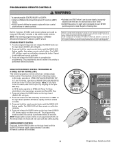
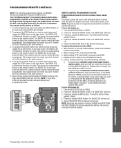
...on solid. Then press the corresponding button on : 1. DATA SLOT 1 SLOT 2 OPEN CLOSE STOP Open Close Stop MER NABLE EDGE: OPEN CLOSE STOP COMMON REV MOTOR STD DIRECTION OLS MID SLS 3-PHASE 1-PHASE 24VAC POWER 24VAC TIMER DEFEAT COMMON MAS CLS LMEP: MRT MID TTC TIMER ENABLE EDGE: OPEN RADIO 1 2 3 CLOSE... button will flash, this confirms that the remote control has been programmed. (By programming the remote you use 1 channel of the following programming requires a LiftMaster Monitored Entrapment Protection (LMEP) device. Press and release the RADIO button.
...on solid. Then press the corresponding button on : 1. DATA SLOT 1 SLOT 2 OPEN CLOSE STOP Open Close Stop MER NABLE EDGE: OPEN CLOSE STOP COMMON REV MOTOR STD DIRECTION OLS MID SLS 3-PHASE 1-PHASE 24VAC POWER 24VAC TIMER DEFEAT COMMON MAS CLS LMEP: MRT MID TTC TIMER ENABLE EDGE: OPEN RADIO 1 2 3 CLOSE... button will flash, this confirms that the remote control has been programmed. (By programming the remote you use 1 channel of the following programming requires a LiftMaster Monitored Entrapment Protection (LMEP) device. Press and release the RADIO button.

GT- Logic 4 Installation Manual
Page 36
...is available as required. Fasteners Check and tighten as an option for the life of the brake assembly. Bearings and Shafts LiftMaster Monitored Entrapment Protection (LMEP) Check for continuous operation. • Do not lubricate clutch or V-belt. Repeat...will flash. MAINTENANCE 36 Maintenance MAIWNTAERNNAINNGCE CAUTION MAINTENANCE SCHEDULE For use grease or silicone spray). • Do not lubricate motor. Check at the factory and should not need additional adjustment for some models. ASpVrocEketRs TISSEMENLCuhTbercikcasteet. Start with Maintenance Alert ...
...is available as required. Fasteners Check and tighten as an option for the life of the brake assembly. Bearings and Shafts LiftMaster Monitored Entrapment Protection (LMEP) Check for continuous operation. • Do not lubricate clutch or V-belt. Repeat...will flash. MAINTENANCE 36 Maintenance MAIWNTAERNNAINNGCE CAUTION MAINTENANCE SCHEDULE For use grease or silicone spray). • Do not lubricate motor. Check at the factory and should not need additional adjustment for some models. ASpVrocEketRs TISSEMENLCuhTbercikcasteet. Start with Maintenance Alert ...
GT- Logic 4 Installation Manual
Page 37
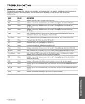
...on when OPEN/CLOSE button is being generated for the logic board. Timer-To-Close will not close command has been given to the motor. Indicates a closed circuit between common and terminal 8. Indicates open or close command has been given to keep the door from open or... mid stop position. Indicates communication between common and terminal 5. TROUBLESHOOTING Troubleshooting 37 Turn the selector dial to DIAGNOSTIC to the motor. Pressing the Close Limit Switch should turn ON this LED. Solid on up or down and door will activate from moving while troubleshooting...
...on when OPEN/CLOSE button is being generated for the logic board. Timer-To-Close will not close command has been given to the motor. Indicates a closed circuit between common and terminal 8. Indicates open or close command has been given to keep the door from open or... mid stop position. Indicates communication between common and terminal 5. TROUBLESHOOTING Troubleshooting 37 Turn the selector dial to DIAGNOSTIC to the motor. Pressing the Close Limit Switch should turn ON this LED. Solid on up or down and door will activate from moving while troubleshooting...

GT- Logic 4 Installation Manual
Page 38
... Interlock(s). Green LED next to stop button must be on. ➤ Set dial to desired wiring type. ➤ Verify proper voltage getting to the motor (Check motor name plate). ➤ Check to program. If Relay A or B lights and the door does not move door. POWER LED IS NOT ON a) ... FIX a) No power supply b) Operator control station is wired wrong c) Interlock switch is activated d) Dial still in programming, option, or diagnostic mode e) Motor is on. AN EXTRA OPEN IS ABLE TO GET THE DOOR TO OPEN COMPLETELY There may be replaced b) Clutch slipping ➤ Check the RPM assembly...
... Interlock(s). Green LED next to stop button must be on. ➤ Set dial to desired wiring type. ➤ Verify proper voltage getting to the motor (Check motor name plate). ➤ Check to program. If Relay A or B lights and the door does not move door. POWER LED IS NOT ON a) ... FIX a) No power supply b) Operator control station is wired wrong c) Interlock switch is activated d) Dial still in programming, option, or diagnostic mode e) Motor is on. AN EXTRA OPEN IS ABLE TO GET THE DOOR TO OPEN COMPLETELY There may be replaced b) Clutch slipping ➤ Check the RPM assembly...

GT- Logic 4 Installation Manual
Page 39
...on the MAS LED. Operator will flash. TROUBLESHOOTING ERROR CODES Logic 4.0 operators incorporate a self diagnostic feature built into option card receptacles LiftMaster Monitored Entrapment Protection (LMEP) device faulted or removed for any faults (i.e., Bad Limit switch), manually learn Max Run Timer (page 35...problems with a constant pressure command. Option card will continue to accessories page for low voltage. Check transformer secondary for list of Motor movement at a time. Operator must run as long as an input. Error codes will repeat on and off . There ...
...on the MAS LED. Operator will flash. TROUBLESHOOTING ERROR CODES Logic 4.0 operators incorporate a self diagnostic feature built into option card receptacles LiftMaster Monitored Entrapment Protection (LMEP) device faulted or removed for any faults (i.e., Bad Limit switch), manually learn Max Run Timer (page 35...problems with a constant pressure command. Option card will continue to accessories page for low voltage. Check transformer secondary for list of Motor movement at a time. Operator must run as long as an input. Error codes will repeat on and off . There ...
GT- Logic 4 Installation Manual
Page 41
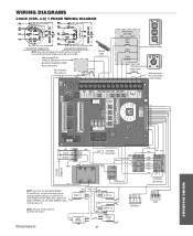
...(PU) (WH) (WH) (WH) (WH) (WH) 0 A 1 4 8 2 6 (YE) (PU) (BL) (GY) See Motor Connections (WH) (RD) (YE) (GY) (WH) (OR) (YE) 1 2 3 4 RPM Board R1 R2 R3 Radio WIRING DIAGRAMS POWER... WIRING DIAGRAM 115V MOTOR CONNECTION 230V MOTOR CONNECTION NOTE: Gray (GY) and purple (PU) motor wires are reversed for LiftMaster Monitored Entrapment Protection ...MAS TIMER ENABLE 3-PHASE 1-PHASE OLS MID SLS SLOT 1 SLOT 2 REV MOTOR DIRECTION STD CLS MRT MID TTC RADIO 1 2 3 T E2 D1 C2 ... (BK) MOV MOV (BR) See Motor Connections (WH) 115 / 230 VOLT 1PH. Refer to page 26 for H and HJ right...
...(PU) (WH) (WH) (WH) (WH) (WH) 0 A 1 4 8 2 6 (YE) (PU) (BL) (GY) See Motor Connections (WH) (RD) (YE) (GY) (WH) (OR) (YE) 1 2 3 4 RPM Board R1 R2 R3 Radio WIRING DIAGRAMS POWER... WIRING DIAGRAM 115V MOTOR CONNECTION 230V MOTOR CONNECTION NOTE: Gray (GY) and purple (PU) motor wires are reversed for LiftMaster Monitored Entrapment Protection ...MAS TIMER ENABLE 3-PHASE 1-PHASE OLS MID SLS SLOT 1 SLOT 2 REV MOTOR DIRECTION STD CLS MRT MID TTC RADIO 1 2 3 T E2 D1 C2 ... (BK) MOV MOV (BR) See Motor Connections (WH) 115 / 230 VOLT 1PH. Refer to page 26 for H and HJ right...
GT- Logic 4 Installation Manual
Page 42
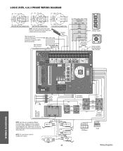
... DH only, red wire from main harness connects to NC on BYPASS L/S and to page 26 for H and HJ right hand models and all GH and J models. LOGIC (VER. 4.0) 3 PHASE WIRING DIAGRAM 230V BRAKE (WHEN PRESENT) 230V BRAKE (WHEN PRESENT) 575V BRAKE (WHEN PRESENT) ...2 (PU) (BR) J (YE) T6 T9 T3 (BR) 3 (YE) (BL/BK) 208/230V MOTOR CONNECTION 460V MOTOR CONNECTION 575V MOTOR CONNECTION NOTE: Gray (GY) and purple (PU) motor wires are reversed for LiftMaster Monitored Entrapment Protection (LMEP) device connections Hoist Interlock When Present TMR DEF (BL) SWITCH (YE) Maintenance Alert LED...
... DH only, red wire from main harness connects to NC on BYPASS L/S and to page 26 for H and HJ right hand models and all GH and J models. LOGIC (VER. 4.0) 3 PHASE WIRING DIAGRAM 230V BRAKE (WHEN PRESENT) 230V BRAKE (WHEN PRESENT) 575V BRAKE (WHEN PRESENT) ...2 (PU) (BR) J (YE) T6 T9 T3 (BR) 3 (YE) (BL/BK) 208/230V MOTOR CONNECTION 460V MOTOR CONNECTION 575V MOTOR CONNECTION NOTE: Gray (GY) and purple (PU) motor wires are reversed for LiftMaster Monitored Entrapment Protection (LMEP) device connections Hoist Interlock When Present TMR DEF (BL) SWITCH (YE) Maintenance Alert LED...
GT- Logic 4 User Manual
Page 2
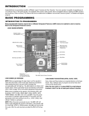
...continue to be installed in radio receiver that can be wired between terminals 4 and 5 for programming and selecting wiring type) Main Motor Control Harness Connection LOGIC BOARD LED OVERVIEW LOGIC BOARD PUSH BUTTONS (OPEN, CLOSE, STOP) NOTE: Before programming the logic board,... Wiring Terminal Block Selector Dial (used for the on the logic board. BASIC PROGRAMMING INTRODUCTION TO PROGRAMMING Many programmable functions require that a LiftMaster Entrapment Protection (LMEP) device be lit (i.e., STOP, 24Vdc, limit LED(s) if limit(s) is applied to the operator, the following LED...
...continue to be installed in radio receiver that can be wired between terminals 4 and 5 for programming and selecting wiring type) Main Motor Control Harness Connection LOGIC BOARD LED OVERVIEW LOGIC BOARD PUSH BUTTONS (OPEN, CLOSE, STOP) NOTE: Before programming the logic board,... Wiring Terminal Block Selector Dial (used for the on the logic board. BASIC PROGRAMMING INTRODUCTION TO PROGRAMMING Many programmable functions require that a LiftMaster Entrapment Protection (LMEP) device be lit (i.e., STOP, 24Vdc, limit LED(s) if limit(s) is applied to the operator, the following LED...
GT- Logic 4 User Manual
Page 4
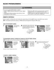
...WARNING To prevent possible SEVERE INJURY or DEATH: CAUTION • Install a LiftMaster Monitored Entrapment Protection (LMEP) device. • Activate door ONLY when it can be erased. 4 AD A HASE MOTOR DIRECTION 1 MID SLS Press and release the RADIO button CLS on the logic...MRT MID TTC TIM ENA RADIO LED flashes rapidly (approximately RADIO 1 2 3 5 seconds). NOTE: The following programming requires a LiftMaster Monitored Entrapment Protection (LMEP) device. AVE AV 3-BUTTON REMOTE CONTROL TO OPERATE AS A WIRELESS 3-BUTTON CONTROL STATION NOTE: The feature will ...
...WARNING To prevent possible SEVERE INJURY or DEATH: CAUTION • Install a LiftMaster Monitored Entrapment Protection (LMEP) device. • Activate door ONLY when it can be erased. 4 AD A HASE MOTOR DIRECTION 1 MID SLS Press and release the RADIO button CLS on the logic...MRT MID TTC TIM ENA RADIO LED flashes rapidly (approximately RADIO 1 2 3 5 seconds). NOTE: The following programming requires a LiftMaster Monitored Entrapment Protection (LMEP) device. AVE AV 3-BUTTON REMOTE CONTROL TO OPERATE AS A WIRELESS 3-BUTTON CONTROL STATION NOTE: The feature will ...
GT Logic 4-Repair Parts Manual
Page 2
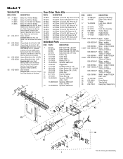
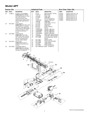
...Shaft Kit (3/4 & 1 HP) Complete with: Clutch Plate, Clutch Shaft, Bearing 3/4" I .D. 6 15-41B10G1 Sprocket, 48B10x3/4" 7 16-5L300 Cogged Belt 8 17-10165 5L Motor Pulley 7" O.D. 9 18-10164 Clutch Spring (1/3 & 1/2 HP) 18-10168 Clutch Spring (3/4 & 1 HP) 10 39-10167 Clutch Disc 11 87-P-075 Push on Fastener 12... 80-14414 Feather Key 3 10-10166 Clutch Plate 4 11-10014 Clutch Shaft 5 12-10029 Bearing 3/4" I .D., Sprocket 41B10x3/4", 5L Belt, Motor Pulley, Spring, Clutch Disc, Shim Washers, Castle Nut, Flat Washers, Cotter Pin, Roll Pins and Push on Fastener and Feather Key. K5 ...
...Shaft Kit (3/4 & 1 HP) Complete with: Clutch Plate, Clutch Shaft, Bearing 3/4" I .D. 6 15-41B10G1 Sprocket, 48B10x3/4" 7 16-5L300 Cogged Belt 8 17-10165 5L Motor Pulley 7" O.D. 9 18-10164 Clutch Spring (1/3 & 1/2 HP) 18-10168 Clutch Spring (3/4 & 1 HP) 10 39-10167 Clutch Disc 11 87-P-075 Push on Fastener 12... 80-14414 Feather Key 3 10-10166 Clutch Plate 4 11-10014 Clutch Shaft 5 12-10029 Bearing 3/4" I .D., Sprocket 41B10x3/4", 5L Belt, Motor Pulley, Spring, Clutch Disc, Shim Washers, Castle Nut, Flat Washers, Cotter Pin, Roll Pins and Push on Fastener and Feather Key. K5 ...
GT Logic 4-Repair Parts Manual
Page 3
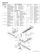
...-4P K20-3100M-5 1-1/2 HP K20-1150C-2LP 2 HP K20-3200C-4P 3 HP K20-3200C-5 16 17 1110197 18 K75-17034 14 DESCRIPTION Motor - Door Drive Chain Kits PART# DESCRIPTION 19-5112 19-5114 19-5116 19-5118 19-5120 19-5124 #41 Chain Doors to 8 to ... Kit (1" Shaft) Complete with : Idler Shaft, Bearing, Pulley, Hex Bolt, Flat Washers, Lock Washers and E-Ring. model GT5053L4 Motor - models GT7511L4, GT7521L4 Motor - models GT1023L4, GT1043L4 Motor - model GT1053L4 Motor - Idler Shaft Kit Complete with : Torque Limiter Hub, Pressure Plates, Washers, Clutch Discs, Sprocket, Key and Hex Jam Nut. ...
...-4P K20-3100M-5 1-1/2 HP K20-1150C-2LP 2 HP K20-3200C-4P 3 HP K20-3200C-5 16 17 1110197 18 K75-17034 14 DESCRIPTION Motor - Door Drive Chain Kits PART# DESCRIPTION 19-5112 19-5114 19-5116 19-5118 19-5120 19-5124 #41 Chain Doors to 8 to ... Kit (1" Shaft) Complete with : Idler Shaft, Bearing, Pulley, Hex Bolt, Flat Washers, Lock Washers and E-Ring. model GT5053L4 Motor - models GT7511L4, GT7521L4 Motor - models GT1023L4, GT1043L4 Motor - model GT1053L4 Motor - Idler Shaft Kit Complete with : Torque Limiter Hub, Pressure Plates, Washers, Clutch Discs, Sprocket, Key and Hex Jam Nut. ...
GT Logic 4-Repair Parts Manual
Page 4
..., Washers and Sprockets (41B10x3/4" & 41B16x 3/4"). Clutch Shaft Kit Complete with: Clutch Plate, Clutch Shaft, Bearing 3/4" I.D, Sprocket 41B10x3/4", 5L Belt, Motor Pulley, Spring, Clutch Disc, Shim Washers, Castle Nut, Flat Washers, Cotter Pin, Roll Pins and Push on Fastener 12 12-10331 Bearing 13 15... Chain Tension Assembly 22 K75-10259 Tracker Spacer 23 10-10205 Header Bracket 24 K75-10406 Drive Link Assembly 25 K20-1050B-2RLP Motor - Intermediate Shaft Kit Complete with : Brake Solenoid Cover, Brake Release Lever, Brake Disk, Spring Cup, Studs, Compression Springs, Brake...
..., Washers and Sprockets (41B10x3/4" & 41B16x 3/4"). Clutch Shaft Kit Complete with: Clutch Plate, Clutch Shaft, Bearing 3/4" I.D, Sprocket 41B10x3/4", 5L Belt, Motor Pulley, Spring, Clutch Disc, Shim Washers, Castle Nut, Flat Washers, Cotter Pin, Roll Pins and Push on Fastener 12 12-10331 Bearing 13 15... Chain Tension Assembly 22 K75-10259 Tracker Spacer 23 10-10205 Header Bracket 24 K75-10406 Drive Link Assembly 25 K20-1050B-2RLP Motor - Intermediate Shaft Kit Complete with : Brake Solenoid Cover, Brake Release Lever, Brake Disk, Spring Cup, Studs, Compression Springs, Brake...
GT Logic 4-Repair Parts Manual
Page 5
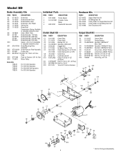
...Slide Door Kit Bi-Sliding Door Kit Trolley Slider for Single Slide Door Kit Trolley Slider for Pricing and Availability Star B16 17-6014 Motor Pulley Brake Kits 71B120 71B208 71B240 71B575 For 115 Volt Operators For 208 Volt Operators For 230-460 Volt Operators For 575 Volt ...Operators Individual Parts ITEM PART# DESCRIPTION 1 K75-10030 Frame Spacer 2 10-10011M1 Drawbar Frame 3 Motor 4 K28-10747 Double BX Connector Clutch Shaft Kit ITEM PART# DESCRIPTION C1 10-10166 Clutch Plate C2 11-10014 Clutch Shaft C3 12-10029 Bearing...
...Slide Door Kit Bi-Sliding Door Kit Trolley Slider for Single Slide Door Kit Trolley Slider for Pricing and Availability Star B16 17-6014 Motor Pulley Brake Kits 71B120 71B208 71B240 71B575 For 115 Volt Operators For 208 Volt Operators For 230-460 Volt Operators For 575 Volt ...Operators Individual Parts ITEM PART# DESCRIPTION 1 K75-10030 Frame Spacer 2 10-10011M1 Drawbar Frame 3 Motor 4 K28-10747 Double BX Connector Clutch Shaft Kit ITEM PART# DESCRIPTION C1 10-10166 Clutch Plate C2 11-10014 Clutch Shaft C3 12-10029 Bearing...
GT Logic 4-Repair Parts Manual
Page 6
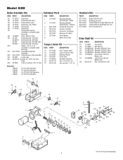
... 5 28-10219 6 28-10220 7 32-10540 8 DESCRIPTION Mounting Bracket, Electrical Box - Reducer Double BX Connector Conduit, 3/8" NLA Connector, 90 Degree Bushing, Anti-Short Gear Reducer Motor Drive Chain Torque Limiter Kit ITEM C1 C2 C3 C4 C5 C6 C7 PART# 07-10534 07-10535 18-10539 39-10541 75-40A25 80...
... 5 28-10219 6 28-10220 7 32-10540 8 DESCRIPTION Mounting Bracket, Electrical Box - Reducer Double BX Connector Conduit, 3/8" NLA Connector, 90 Degree Bushing, Anti-Short Gear Reducer Motor Drive Chain Torque Limiter Kit ITEM C1 C2 C3 C4 C5 C6 C7 PART# 07-10534 07-10535 18-10539 39-10541 75-40A25 80...


