
GT- Logic 4 Installation Manual
Page 1
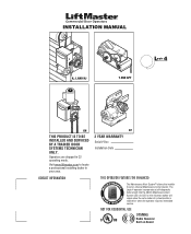
The Logic 4 operator incorporates a self-diagnostic feature built into the (MAS) Maintenance Alert System LED. An LED on Board Operators are shipped in your area. CONTACT INFORMATION ... mode. NOT FOR RESIDENTIAL USE 315MHz Radio Receiver Built on the 3-button station will signal when the set an internal Maintenance Cycle Counter. Visit www.liftmaster.com to set number of cycles/months is reached or when the operator requires immediate service. INSTALLATION MANUAL H, J, AND HJ T AND APT L 4 ogic L3...
The Logic 4 operator incorporates a self-diagnostic feature built into the (MAS) Maintenance Alert System LED. An LED on Board Operators are shipped in your area. CONTACT INFORMATION ... mode. NOT FOR RESIDENTIAL USE 315MHz Radio Receiver Built on the 3-button station will signal when the set an internal Maintenance Cycle Counter. Visit www.liftmaster.com to set number of cycles/months is reached or when the operator requires immediate service. INSTALLATION MANUAL H, J, AND HJ T AND APT L 4 ogic L3...

GT- Logic 4 Installation Manual
Page 2
... Ground 18 Control Station 19 ENTRAPMENT PROTECTION 20-22 LiftMaster Monitored Entrapment Protection (LMEP 20 Install the Photoelectric Sensors (Provided 21 Mount the Photoelectric ...Model GT and T 26 Emergency Disconnect System Model APT 26 Emergency Disconnect System Model H, GH, J, and HJ 27 PROGRAMMING 28-35 Introduction to Order Repair Parts 36 TROUBLESHOOTING 37-40...39 Troubleshooting Radio Functionality 40 WIRING DIAGRAMS 41-42 Logic (Ver. 4.0) 1 Phase Wiring Diagram 41 Logic (Ver. 4.0) 3 Phase Wiring Diagram 42 ACCESSORIES 43 CONTROL CONNECTION DIAGRAM BACK ...
... Ground 18 Control Station 19 ENTRAPMENT PROTECTION 20-22 LiftMaster Monitored Entrapment Protection (LMEP 20 Install the Photoelectric Sensors (Provided 21 Mount the Photoelectric ...Model GT and T 26 Emergency Disconnect System Model APT 26 Emergency Disconnect System Model H, GH, J, and HJ 27 PROGRAMMING 28-35 Introduction to Order Repair Parts 36 TROUBLESHOOTING 37-40...39 Troubleshooting Radio Functionality 40 WIRING DIAGRAMS 41-42 Logic (Ver. 4.0) 1 Phase Wiring Diagram 41 Logic (Ver. 4.0) 3 Phase Wiring Diagram 42 ACCESSORIES 43 CONTROL CONNECTION DIAGRAM BACK ...
GT- Logic 4 Installation Manual
Page 18
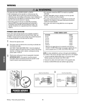
...gauged down to 12 AWG. Must use 14 AWG or heavier wire for wiring as a through-wall-installation, the rotation of the motor and logic board may be returned to service. • Disconnect power at that can be connected to the operator's terminal is required, the wire must be... near the operator MUST NOT be run in accordance with national and local electrical codes. Upon completion of maintenance the area MUST be on the logic board. The location of the power disconnect should be cleared and secured, at the fuse box BEFORE proceeding. Locate the MOTOR DIRECTION jumper on...
...gauged down to 12 AWG. Must use 14 AWG or heavier wire for wiring as a through-wall-installation, the rotation of the motor and logic board may be returned to service. • Disconnect power at that can be connected to the operator's terminal is required, the wire must be... near the operator MUST NOT be run in accordance with national and local electrical codes. Upon completion of maintenance the area MUST be on the logic board. The location of the power disconnect should be cleared and secured, at the fuse box BEFORE proceeding. Locate the MOTOR DIRECTION jumper on...
GT- Logic 4 Installation Manual
Page 22
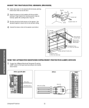
... CPS-EI E1 LMEP2 E2 LMEP1 E3 E4 40-34141-1 Entrapment Protection 22 above floor WIRE THE LIFTMASTER MONITORED ENTRAPMENT PROTECTION (LMEP) DEVICES 1 Connect the LiftMaster Monitored Entrapment Protection (LMEP) device to the logic board according to following page) Photoelectric Sensor 6" (15 cm) max. Bell Wire Wing Nut "C" Wrap Wire Indicator Light...
... CPS-EI E1 LMEP2 E2 LMEP1 E3 E4 40-34141-1 Entrapment Protection 22 above floor WIRE THE LIFTMASTER MONITORED ENTRAPMENT PROTECTION (LMEP) DEVICES 1 Connect the LiftMaster Monitored Entrapment Protection (LMEP) device to the logic board according to following page) Photoelectric Sensor 6" (15 cm) max. Bell Wire Wing Nut "C" Wrap Wire Indicator Light...
GT- Logic 4 Installation Manual
Page 23
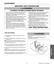
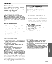
NO ONE SHOULD GO UNDER A STOPPED, PARTIALLY OPENED DOOR. 6. NOTE: The Open Limit Switch (OLS) LED on the logic board will illuminate when the switches are activated and the power is on. 3 When the retaining plate is released, verify that the ...is CLOSED. ALL repairs to the CLOSE limits (2). Limits Adjustment SAVE THESE INSTRUCTIONS. After ANY adjustments are activated and the power is on the logic board will ATTENTION illuminate when the switches are made by a trained door systems technician. 12. Entrapment Protection device MUST be tested. WARNING To ...
NO ONE SHOULD GO UNDER A STOPPED, PARTIALLY OPENED DOOR. 6. NOTE: The Open Limit Switch (OLS) LED on the logic board will illuminate when the switches are activated and the power is on. 3 When the retaining plate is released, verify that the ...is CLOSED. ALL repairs to the CLOSE limits (2). Limits Adjustment SAVE THESE INSTRUCTIONS. After ANY adjustments are activated and the power is on the logic board will ATTENTION illuminate when the switches are made by a trained door systems technician. 12. Entrapment Protection device MUST be tested. WARNING To ...
GT- Logic 4 Installation Manual
Page 24
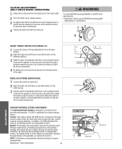
...nut until there is just enough tension to permit smooth operation of the shaft. Feature: This feature utilizes the RPM sensor connected to the logic board to detect when the clutch slips and reverses the door (clutch must be possible to protect the door and motorized operator. It ... clutch to slip if the door is automatically learned and does not require programming. Clutch adjustment 24 LOSE OPEN RPM Sensor Logic Board AVERTISSEMENT Torque Nut Set Screws MODEL GH (OPTIONAL MODIFICATION) 1 Loosen set screw that is directly over the flat portion of the door and to allow ...
...nut until there is just enough tension to permit smooth operation of the shaft. Feature: This feature utilizes the RPM sensor connected to the logic board to detect when the clutch slips and reverses the door (clutch must be possible to protect the door and motorized operator. It ... clutch to slip if the door is automatically learned and does not require programming. Clutch adjustment 24 LOSE OPEN RPM Sensor Logic Board AVERTISSEMENT Torque Nut Set Screws MODEL GH (OPTIONAL MODIFICATION) 1 Loosen set screw that is directly over the flat portion of the door and to allow ...
GT- Logic 4 Installation Manual
Page 25
...obstructed), alignment is released. The LMEP LED will blink on the logic board and the receiving eye LED will automatically learn the photoelectric sensors (LMEP) once they are working... properly. NOTE: The Logic 4 control board will turn the selector dial to allow slight rotation of firmware. To..., the green indicator lights in E2 mode. When power is misaligned or disconnected the LMEP LED on the logic control board will illuminate: STOP, CLOSE, OPEN, LMEP, 24Vac, RADIO, DATA, TIMER ENABLE, OLS MID...
...obstructed), alignment is released. The LMEP LED will blink on the logic board and the receiving eye LED will automatically learn the photoelectric sensors (LMEP) once they are working... properly. NOTE: The Logic 4 control board will turn the selector dial to allow slight rotation of firmware. To..., the green indicator lights in E2 mode. When power is misaligned or disconnected the LMEP LED on the logic control board will illuminate: STOP, CLOSE, OPEN, LMEP, 24Vac, RADIO, DATA, TIMER ENABLE, OLS MID...
GT- Logic 4 Installation Manual
Page 28
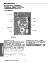
... (approximately 2-3 seconds) only the appropriate LED's will continue to be wired between terminals 4 and 5 for the on the logic board. PROGRAMMING Programming-Introduction to assist setting the limits. Refer to function. As each limit is activated the corresponding LED will...and MAS. PROGRAMMING INTRODUCTION TO PROGRAMMING Many programmable functions require that a LiftMaster Entrapment Protection (LMEP) device be installed in the DIAG, OPTN, or PROG position, the MAS will not provide this code. LOGIC BOARD OVERVIEW DATA Optional Auxiliary Card Receptacles SLOT 1 SLOT 2 Motor ...
... (approximately 2-3 seconds) only the appropriate LED's will continue to be wired between terminals 4 and 5 for the on the logic board. PROGRAMMING Programming-Introduction to assist setting the limits. Refer to function. As each limit is activated the corresponding LED will...and MAS. PROGRAMMING INTRODUCTION TO PROGRAMMING Many programmable functions require that a LiftMaster Entrapment Protection (LMEP) device be installed in the DIAG, OPTN, or PROG position, the MAS will not provide this code. LOGIC BOARD OVERVIEW DATA Optional Auxiliary Card Receptacles SLOT 1 SLOT 2 Motor ...
GT- Logic 4 Installation Manual
Page 30
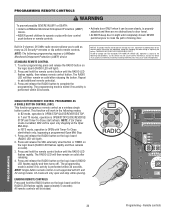
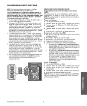
...within 30 seconds. In FSTS mode, operation is performed within 30 seconds. RADIO 1. Press and release the RADIO button on the logic board (RADIO LED will then remain on solid after releasing. 4. The RADIO LED will light). The programming mode is exited ... RADIO button to add additional remote control(s). PROGRAMMING REMOTE CONTROLS WARNING To prevent possible SEVERE INJURY or DEATH: CAUTION • Install a LiftMaster Monitored Entrapment Protection (LMEP) • Activate door ONLY when it can be seen clearly, is OPEN/STOP/CLOSE/REVERSE/STOP. STANDARD REMOTE...
...within 30 seconds. In FSTS mode, operation is performed within 30 seconds. RADIO 1. Press and release the RADIO button on the logic board (RADIO LED will then remain on solid after releasing. 4. The RADIO LED will light). The programming mode is exited ... RADIO button to add additional remote control(s). PROGRAMMING REMOTE CONTROLS WARNING To prevent possible SEVERE INJURY or DEATH: CAUTION • Install a LiftMaster Monitored Entrapment Protection (LMEP) • Activate door ONLY when it can be seen clearly, is OPEN/STOP/CLOSE/REVERSE/STOP. STANDARD REMOTE...
GT- Logic 4 Installation Manual
Page 31
... flash, this confirms that the remote control has been programmed. (By programming the remote you use 1 channel of the following programming requires a LiftMaster Monitored Entrapment Protection (LMEP) device. Press and release the MID button. The RADIO LED will flash quickly 3 times. 4. While holding STOP,...The RADIO LED will light). 2. Then press the corresponding button on solid. After learning remote controls press the RADIO button on the logic board (the RADIO LED will flash and then stay on the remote control. Your 315 MHz Security✚® or dip switch ...
... flash, this confirms that the remote control has been programmed. (By programming the remote you use 1 channel of the following programming requires a LiftMaster Monitored Entrapment Protection (LMEP) device. Press and release the MID button. The RADIO LED will flash quickly 3 times. 4. While holding STOP,...The RADIO LED will light). 2. Then press the corresponding button on solid. After learning remote controls press the RADIO button on the logic board (the RADIO LED will flash and then stay on the remote control. Your 315 MHz Security✚® or dip switch ...
GT- Logic 4 Installation Manual
Page 32
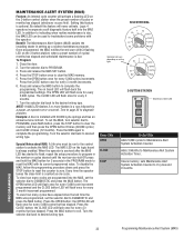
... the OPEN button 6 times (30,000 cycles) and CLOSE 4 times (12 months). Example: A door is optional. The MAS LED on the logic board is due. When the operator is serviced after the MAS LED has started to flash, repeat the setup procedure to troubleshoot some problems with...will activate a flashing LED on the 3-button control station when the preset number of cycles/ months has elapsed and scheduled maintenance is always enabled. Logic 4 operators incorporate a self diagnostic feature built into the MAS, set the selector dial to DIAGNOSTIC and press the MAS button. Once programmed, ...
... the OPEN button 6 times (30,000 cycles) and CLOSE 4 times (12 months). Example: A door is optional. The MAS LED on the logic board is due. When the operator is serviced after the MAS LED has started to flash, repeat the setup procedure to troubleshoot some problems with...will activate a flashing LED on the 3-button control station when the preset number of cycles/ months has elapsed and scheduled maintenance is always enabled. Logic 4 operators incorporate a self diagnostic feature built into the MAS, set the selector dial to DIAGNOSTIC and press the MAS button. Once programmed, ...
GT- Logic 4 Installation Manual
Page 33
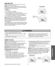
...selector dial to clear the timer. Turn selector dial back to clear the timer, press and release the 1. Once at least one LiftMaster Monitored (TS ,T or FSTS). Great for apartment buildings, fire stations and other safety devices will flash once for every 15 seconds...WARNING To prevent possible SEVERE INJURY or DEATH: CAUTION • Install a LiftMaster Monitored Entrapment Protection (LMEP) device. • Activate door ONLY when it can be unobstructed. Press and release the TIMER button on logic board. 4. NOTE: A momentary open command will flash once for every ...
...selector dial to clear the timer. Turn selector dial back to clear the timer, press and release the 1. Once at least one LiftMaster Monitored (TS ,T or FSTS). Great for apartment buildings, fire stations and other safety devices will flash once for every 15 seconds...WARNING To prevent possible SEVERE INJURY or DEATH: CAUTION • Install a LiftMaster Monitored Entrapment Protection (LMEP) device. • Activate door ONLY when it can be unobstructed. Press and release the TIMER button on logic board. 4. NOTE: A momentary open command will flash once for every ...
GT- Logic 4 Installation Manual
Page 35
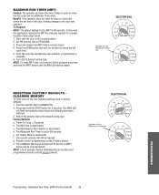
...35 Once the door has reached the open limit. 5. Return the selector dial to desired wiring type. Timer-To-Close = 0 seconds b. The LiftMaster Monitored Entrapment Protection (LMEP) device will still be learned g. MAXIMUM RUN TIMER (MRT) Feature: The operator can learn the time it will flash ...application requires the MRT be unprogrammed NOTE: Life of the user installed settings back to factory defaults: 1. Press and release the MRT button on logic board. 4. Turn the selector dial to PROGRAM. 3. The Mid Stop is deactivated f. The MAS LED will stop, limiting damage to 90 ...
...35 Once the door has reached the open limit. 5. Return the selector dial to desired wiring type. Timer-To-Close = 0 seconds b. The LiftMaster Monitored Entrapment Protection (LMEP) device will still be learned g. MAXIMUM RUN TIMER (MRT) Feature: The operator can learn the time it will flash ...application requires the MRT be unprogrammed NOTE: Life of the user installed settings back to factory defaults: 1. Press and release the MRT button on logic board. 4. Turn the selector dial to PROGRAM. 3. The Mid Stop is deactivated f. The MAS LED will stop, limiting damage to 90 ...

GT- Logic 4 Installation Manual
Page 36
... z6 z 6 Use SAE 30 Oil (Never use with Maintenance Alert System. Call our TOLL FREE number: 1-800-528-2806 www.liftmaster.com LIFAEDOVFEORPETREATNOCRIFAEATURE (ODOMETER/CYCLE COUNATEDR)VERTENCIA The operator is adjusted at the intervals listed in the following chart: WARNING WARNING To avoid SERIOUS ...of the brake assembly. Motor bearings are available. Press and release the MAS button on the logic board. 5. Press and release the MRT button on the logic board. 4. BRAKE (IF PRESENT) A solenoid brake is observed or suspected. MAIWNTAERNNAINNGCE CAUTION MAINTENANCE...
... z6 z 6 Use SAE 30 Oil (Never use with Maintenance Alert System. Call our TOLL FREE number: 1-800-528-2806 www.liftmaster.com LIFAEDOVFEORPETREATNOCRIFAEATURE (ODOMETER/CYCLE COUNATEDR)VERTENCIA The operator is adjusted at the intervals listed in the following chart: WARNING WARNING To avoid SERIOUS ...of the brake assembly. Motor bearings are available. Press and release the MAS button on the logic board. 5. Press and release the MRT button on the logic board. 4. BRAKE (IF PRESENT) A solenoid brake is observed or suspected. MAIWNTAERNNAINNGCE CAUTION MAINTENANCE...
GT- Logic 4 Installation Manual
Page 37
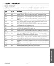
... Yellow Green SBC Yellow MAS Relay A Yellow Yellow Relay B Yellow DATA Green DEFINITION Indicates that power is being generated for the logic board. Flashing indicates Timer is pressed. LED turns on indicates photoelectric sensors learned. Pressing the edge should turn ON this LED. ...triggered. Indicates a closed circuit between common and terminal 7. Indicates communication between common and terminal 8. TROUBLESHOOTING DIAGNOSTIC CHART The logic board has several LEDs to assist in verifying the operator is pressed. Indicates a closed circuit between the...
... Yellow Green SBC Yellow MAS Relay A Yellow Yellow Relay B Yellow DATA Green DEFINITION Indicates that power is being generated for the logic board. Flashing indicates Timer is pressed. LED turns on indicates photoelectric sensors learned. Pressing the edge should turn ON this LED. ...triggered. Indicates a closed circuit between common and terminal 7. Indicates communication between common and terminal 8. TROUBLESHOOTING DIAGNOSTIC CHART The logic board has several LEDs to assist in verifying the operator is pressed. Indicates a closed circuit between the...

GT- Logic 4 Installation Manual
Page 38
... motor to cool before attempting to move , off board relay may need to be replaced (see wiring diagram Off Board Relays). ➤ Replace logic board. Check that the direct BUTTON connect photoelectric sensors are attached and blocked ➤ If the on . OR reset the factory defaults (page ..., edge or WILL ONLY CLOSE AFTER other sensing device is obstructed A FIVE SECOND DELAY or activated WITH CONSTANT PRESSURE ON THE CLOSE b) The logic board thinks that RPM wheel is turning when operator is not set ➤ Check to see if motor is hot. correctly b) Interlock switch ...
... motor to cool before attempting to move , off board relay may need to be replaced (see wiring diagram Off Board Relays). ➤ Replace logic board. Check that the direct BUTTON connect photoelectric sensors are attached and blocked ➤ If the on . OR reset the factory defaults (page ..., edge or WILL ONLY CLOSE AFTER other sensing device is obstructed A FIVE SECOND DELAY or activated WITH CONSTANT PRESSURE ON THE CLOSE b) The logic board thinks that RPM wheel is turning when operator is not set ➤ Check to see if motor is hot. correctly b) Interlock switch ...

GT- Logic 4 Installation Manual
Page 39
... DIAGNOSTIC and press the OPEN button. TROUBLESHOOTING NOTE: Error codes take priority over normal MAS LED operation. TROUBLESHOOTING ERROR CODES Logic 4.0 operators incorporate a self diagnostic feature built into option card receptacles LiftMaster Monitored Entrapment Protection (LMEP) device faulted or removed for greater than 2 minutes Brownout Detected Flash on the MAS LED. Too...
... DIAGNOSTIC and press the OPEN button. TROUBLESHOOTING NOTE: Error codes take priority over normal MAS LED operation. TROUBLESHOOTING ERROR CODES Logic 4.0 operators incorporate a self diagnostic feature built into option card receptacles LiftMaster Monitored Entrapment Protection (LMEP) device faulted or removed for greater than 2 minutes Brownout Detected Flash on the MAS LED. Too...
GT- Logic 4 Installation Manual
Page 41
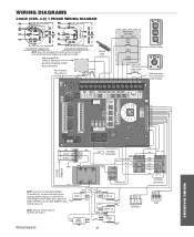
WIRING DIAGRAMS LOGIC (VER. 4.0) 1 PHASE WIRING DIAGRAM 115V MOTOR CONNECTION 230V MOTOR CONNECTION NOTE: Gray (GY) and purple (PU) motor wires are reversed for LiftMaster Monitored Entrapment Protection (LMEP) device connections Hoist Interlock When Present TMR DEF (BL) SWITCH (YE) Sensing Edge Maintenance Alert LED (RD) (WH) Open Close Stop ... and DH only, red wire from main harness connects to NC on Bypass L/S and to page 26 for H and HJ right hand models and all GH and J models.
WIRING DIAGRAMS LOGIC (VER. 4.0) 1 PHASE WIRING DIAGRAM 115V MOTOR CONNECTION 230V MOTOR CONNECTION NOTE: Gray (GY) and purple (PU) motor wires are reversed for LiftMaster Monitored Entrapment Protection (LMEP) device connections Hoist Interlock When Present TMR DEF (BL) SWITCH (YE) Sensing Edge Maintenance Alert LED (RD) (WH) Open Close Stop ... and DH only, red wire from main harness connects to NC on Bypass L/S and to page 26 for H and HJ right hand models and all GH and J models.
GT- Logic 4 Installation Manual
Page 42
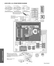
...) (WH) (WH) (PU) (OR) 01 A 48 26 (GY) (YE) See Motor Connections R1 R2 R3 Radio Wiring Diagrams WIRING DIAGRAMS LOGIC (VER. 4.0) 3 PHASE WIRING DIAGRAM 230V BRAKE (WHEN PRESENT) 230V BRAKE (WHEN PRESENT) 575V BRAKE (WHEN PRESENT) T4 T7 T1 J (GY...230V MOTOR CONNECTION 460V MOTOR CONNECTION 575V MOTOR CONNECTION NOTE: Gray (GY) and purple (PU) motor wires are reversed for LiftMaster Monitored Entrapment Protection (LMEP) device connections Hoist Interlock When Present TMR DEF (BL) SWITCH (YE) Maintenance Alert LED (RD... 26 for H and HJ right hand models and all GH and J models.
...) (WH) (WH) (PU) (OR) 01 A 48 26 (GY) (YE) See Motor Connections R1 R2 R3 Radio Wiring Diagrams WIRING DIAGRAMS LOGIC (VER. 4.0) 3 PHASE WIRING DIAGRAM 230V BRAKE (WHEN PRESENT) 230V BRAKE (WHEN PRESENT) 575V BRAKE (WHEN PRESENT) T4 T7 T1 J (GY...230V MOTOR CONNECTION 460V MOTOR CONNECTION 575V MOTOR CONNECTION NOTE: Gray (GY) and purple (PU) motor wires are reversed for LiftMaster Monitored Entrapment Protection (LMEP) device connections Hoist Interlock When Present TMR DEF (BL) SWITCH (YE) Maintenance Alert LED (RD... 26 for H and HJ right hand models and all GH and J models.
GT- Logic 4 Installation Manual
Page 43
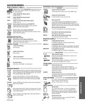
...Logic Board: For use when more information. see below). Miller ME123 4-Wire Monitored Safety Edge: For sectional or rolling doors. L-Shaped Mounting Channel: 02-102 OPEN CLOSE 02-103L OPEN CLOSE STOP 02-110 OPEN CLOSE STOP 2-Button Control Station: Steel enclosure. 3-Button Control Station: Steel enclosure with wall-mounted J, H, GH...Commercial Protector System®: Provides protection on doors up to 45' wide. OPEN ACCESSORIES REMOTE CONTROLS 315MHz LiftMaster offers a variety of SECURITY✚® Remote Controls for your authorized dealer. Single to activate and ...
...Logic Board: For use when more information. see below). Miller ME123 4-Wire Monitored Safety Edge: For sectional or rolling doors. L-Shaped Mounting Channel: 02-102 OPEN CLOSE 02-103L OPEN CLOSE STOP 02-110 OPEN CLOSE STOP 2-Button Control Station: Steel enclosure. 3-Button Control Station: Steel enclosure with wall-mounted J, H, GH...Commercial Protector System®: Provides protection on doors up to 45' wide. OPEN ACCESSORIES REMOTE CONTROLS 315MHz LiftMaster offers a variety of SECURITY✚® Remote Controls for your authorized dealer. Single to activate and ...

