

GT- Logic 4 Installation Manual
Page 2
...Door Area 14 Weights and Dimensions 15 ASSEMBLY 16 Assemble the Operator 16 TYPICAL INSTALLATION 16-17 Determine Mounting Location 16 Mounting 17 Install the Manual Disconnect 17 WIRING 18-19 Power and Ground 18 Control Station 19 ENTRAPMENT PROTECTION 20-22 LiftMaster...T 26 Emergency Disconnect System Model APT 26 Emergency Disconnect System Model H, GH, J, and HJ 27 PROGRAMMING 28-35 Introduction to Order Repair Parts ...Remote Controls 30-31 Maintenance Alert System (MAS 32 Open Mid Stop 33 Timer-To-Close 33-34 Car Dealer Mode 34 Maximum Run Timer...
...Door Area 14 Weights and Dimensions 15 ASSEMBLY 16 Assemble the Operator 16 TYPICAL INSTALLATION 16-17 Determine Mounting Location 16 Mounting 17 Install the Manual Disconnect 17 WIRING 18-19 Power and Ground 18 Control Station 19 ENTRAPMENT PROTECTION 20-22 LiftMaster...T 26 Emergency Disconnect System Model APT 26 Emergency Disconnect System Model H, GH, J, and HJ 27 PROGRAMMING 28-35 Introduction to Order Repair Parts ...Remote Controls 30-31 Maintenance Alert System (MAS 32 Open Mid Stop 33 Timer-To-Close 33-34 Car Dealer Mode 34 Maximum Run Timer...

GT- Logic 4 Installation Manual
Page 4
... PROTECTION: LiftMaster Monitored Entrapment Protection (LMEP) Photoelectric Sensors (CPS-U Through beam used to the bottom edge of door. Safety Edge (Optional Electric or pneumatic sensing device attached to provide non-contact safety protection. See page 29 for emergency manual door operation. ...DESCRIPTION Powerhead assembly Owner's manual and caution labels Hardware box (includes fasteners, track spacers, trolley, door arm assembly, front idler and header mounting bracket) 3-Button control station with open and close with LED Trolley drive chain: #48 for 1/3 and 1/2 HP, #41 for...
... PROTECTION: LiftMaster Monitored Entrapment Protection (LMEP) Photoelectric Sensors (CPS-U Through beam used to the bottom edge of door. Safety Edge (Optional Electric or pneumatic sensing device attached to provide non-contact safety protection. See page 29 for emergency manual door operation. ...DESCRIPTION Powerhead assembly Owner's manual and caution labels Hardware box (includes fasteners, track spacers, trolley, door arm assembly, front idler and header mounting bracket) 3-Button control station with open and close with LED Trolley drive chain: #48 for 1/3 and 1/2 HP, #41 for...
GT- Logic 4 Installation Manual
Page 10
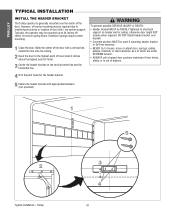
... appropriate hardware (not provided). AVERTISSEMENT 5 Fasten the header bracket with a vertical line, extend the line onto the ceiling. 2 Open the door to the highest point of travel . 3 Center the header bracket on the vertical center line and the horizontal line. 4 Drill the...bracket or 2x4 into masonry. • NEVER try to loosen, move or adjust door, springs, cables, pulleys, brackets, or their hardware, ALL of which are under EXTREME tension. • ALWAYS call a trained door systems technician if door binds, sticks, or is generally mounted over drywall. • Concrete anchors MUST...
... appropriate hardware (not provided). AVERTISSEMENT 5 Fasten the header bracket with a vertical line, extend the line onto the ceiling. 2 Open the door to the highest point of travel . 3 Center the header bracket on the vertical center line and the horizontal line. 4 Drill the...bracket or 2x4 into masonry. • NEVER try to loosen, move or adjust door, springs, cables, pulleys, brackets, or their hardware, ALL of which are under EXTREME tension. • ALWAYS call a trained door systems technician if door binds, sticks, or is generally mounted over drywall. • Concrete anchors MUST...
GT- Logic 4 Installation Manual
Page 12
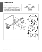
... 3/8"-16 x 1" (3) NOTICE 1 A B 2 Typical installation - TROLLEY ATTACH THE DOOR ARM 1 Latch the door arm to door manufacturer's instructions for recommended installation guidelines. Make sure the open side of the notch on the door arm faces the door. 2 Position the door bracket to the center line of the door and attach the door bracket to the door using appropriate hardware (not included).
... 3/8"-16 x 1" (3) NOTICE 1 A B 2 Typical installation - TROLLEY ATTACH THE DOOR ARM 1 Latch the door arm to door manufacturer's instructions for recommended installation guidelines. Make sure the open side of the notch on the door arm faces the door. 2 Position the door bracket to the center line of the door and attach the door bracket to the door using appropriate hardware (not included).

GT- Logic 4 Installation Manual
Page 13
...open and close with open override. ELECTRICAL TRANSFORMER 24Vac Secondary CONTROL STATION NEMA 3-Button Station Open/Close/Stop w/LED WIRING TYPE C2 (Standard) Momentary contact to OPEN...216;, 60Hz 3 3.1 4 6 460-3Ø, 60Hz 1.5 1.75 2 3 575-3Ø, 60Hz 1.3 1.4 1.6 1.8 Model GH Voltage-Phase 1/2 HP 3/4 HP 1 HP 1-1/2 HP 2 HP 3 HP 115-1Ø, 60Hz 11.2 13.6 16 20 ...75 3 - See page 29 for manual door operation Model HJ Includes both floor level disconnect systems stated above ENTRAPMENT PROTECTION: LiftMaster Monitored Entrapment Protection (LMEP) Photoelectric Sensors (...
...open and close with open override. ELECTRICAL TRANSFORMER 24Vac Secondary CONTROL STATION NEMA 3-Button Station Open/Close/Stop w/LED WIRING TYPE C2 (Standard) Momentary contact to OPEN...216;, 60Hz 3 3.1 4 6 460-3Ø, 60Hz 1.5 1.75 2 3 575-3Ø, 60Hz 1.3 1.4 1.6 1.8 Model GH Voltage-Phase 1/2 HP 3/4 HP 1 HP 1-1/2 HP 2 HP 3 HP 115-1Ø, 60Hz 11.2 13.6 16 20 ...75 3 - See page 29 for manual door operation Model HJ Includes both floor level disconnect systems stated above ENTRAPMENT PROTECTION: LiftMaster Monitored Entrapment Protection (LMEP) Photoelectric Sensors (...

GT- Logic 4 Installation Manual
Page 16
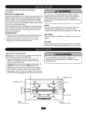
...The optimum distance between the operator and the door shaft. On models J, H, HJ and GH operators the drive sprocket can cause SERIOUS PERSONAL INJURY. • Disable ALL locks and remove ALL ropes connected to door AVERTISSEMENT BEFORE installing and operating door operator to avoid entanglement. • Fasten ... your ATTENTION installation causes the hand chain to hang in the door opening, hook the chain to structural supports of which are under EXTREME tension and can be switched. Provide a level base. An unbalanced door may be used if installing ANY brackets. Be rigid to prevent...
...The optimum distance between the operator and the door shaft. On models J, H, HJ and GH operators the drive sprocket can cause SERIOUS PERSONAL INJURY. • Disable ALL locks and remove ALL ropes connected to door AVERTISSEMENT BEFORE installing and operating door operator to avoid entanglement. • Fasten ... your ATTENTION installation causes the hand chain to hang in the door opening, hook the chain to structural supports of which are under EXTREME tension and can be switched. Provide a level base. An unbalanced door may be used if installing ANY brackets. Be rigid to prevent...
GT- Logic 4 Installation Manual
Page 19
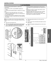
... TIMER DEFEAT MAS 10 COMMON MAS LMEP 9 LMEP: TIMER NABLE EDGE: OPEN EDGE 8 CLOSE OPEN ADVERTSTOP ENCIA 7 COMMON CLOSE 6 N STOP 5 ADVERTENCIA SBC COMMON 4 UL Entrapment Placard WARNING 3 2 SBC 1 3-Button Station OPEN CLOSE STOP Maintenance Alert LED (RD) (WH) Open Close Stop Moving Door Can Cause Serious Injury or Death Keep Clear! The installation surface must...
... TIMER DEFEAT MAS 10 COMMON MAS LMEP 9 LMEP: TIMER NABLE EDGE: OPEN EDGE 8 CLOSE OPEN ADVERTSTOP ENCIA 7 COMMON CLOSE 6 N STOP 5 ADVERTENCIA SBC COMMON 4 UL Entrapment Placard WARNING 3 2 SBC 1 3-Button Station OPEN CLOSE STOP Maintenance Alert LED (RD) (WH) Open Close Stop Moving Door Can Cause Serious Injury or Death Keep Clear! The installation surface must...
GT- Logic 4 Installation Manual
Page 33
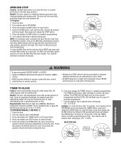
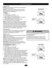
... OPTN PROG WARNING To prevent possible SEVERE INJURY or DEATH: CAUTION • Install a LiftMaster Monitored Entrapment Protection (LMEP) device. • Activate door ONLY when it can be unobstructed. automatically after preset amount of setting. Press and release the OPEN button for 10 seconds. SELECTOR DIAL T E2 D1 TS FSTS DIAG Operation will flash...
... OPTN PROG WARNING To prevent possible SEVERE INJURY or DEATH: CAUTION • Install a LiftMaster Monitored Entrapment Protection (LMEP) device. • Activate door ONLY when it can be unobstructed. automatically after preset amount of setting. Press and release the OPEN button for 10 seconds. SELECTOR DIAL T E2 D1 TS FSTS DIAG Operation will flash...
GT- Logic 4 Installation Manual
Page 34
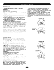
...). Turn the selector dial to the desired wiring type (TS or T). T wiring mode allows the door to attempt to the SBC input and must be activated by limiting the door opening height. To enable this feature you must first connect a treadle, photoelectric sensor or loop detector accessory ... LED will flash once for desired amount of time to DIAGNOSTIC and press the TIMER button. To deactivate the timer for the door to -close only one LiftMaster Monitored Entrapment Protection (LMEP) device installed (refer to TS or T. Benefit: Provides energy cost savings by the Single Button Control...
...). Turn the selector dial to the desired wiring type (TS or T). T wiring mode allows the door to attempt to the SBC input and must be activated by limiting the door opening height. To enable this feature you must first connect a treadle, photoelectric sensor or loop detector accessory ... LED will flash once for desired amount of time to DIAGNOSTIC and press the TIMER button. To deactivate the timer for the door to -close only one LiftMaster Monitored Entrapment Protection (LMEP) device installed (refer to TS or T. Benefit: Provides energy cost savings by the Single Button Control...

GT- Logic 4 User Manual
Page 9
...your area visit us online at www.liftmaster.com CONDITION POSSIBLE CAUSE OPERATOR WILL NOT RESPOND TO ANY No power COMMANDS OPERATOR MAKES NOISE BUT DOOR DOES NOT MOVE DOOR DRIFTS AFTER OPERATOR STOPS DOOR OPENS/ CLOSES TOO FAR Accessory failure Possible component... failure Operator requires adjustment Operator or door requires adjustment Operator requires adjustment DOOR REVERSES UNEXPECTEDLY Entrapment protection device activated...
...your area visit us online at www.liftmaster.com CONDITION POSSIBLE CAUSE OPERATOR WILL NOT RESPOND TO ANY No power COMMANDS OPERATOR MAKES NOISE BUT DOOR DOES NOT MOVE DOOR DRIFTS AFTER OPERATOR STOPS DOOR OPENS/ CLOSES TOO FAR Accessory failure Possible component... failure Operator requires adjustment Operator or door requires adjustment Operator requires adjustment DOOR REVERSES UNEXPECTEDLY Entrapment protection device activated...
GT- Logic 4 User Manual
Page 11
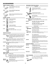
... (25') Antenna Extension Kit: The antenna extension kit can be used to mount J, H, DH, DJ, and GH side mount operators on doors up to provide special timer functions. OPEN CLOSE CONTROL STATIONS 02-101 1-Button Control Station: OPEN Steel enclosure. STOP MOUNTING BRACKETS ENTRAPMENT PROTECTION DEVICES MONITORED CPS-UN4 Commercial Protector System®: Provides...
... (25') Antenna Extension Kit: The antenna extension kit can be used to mount J, H, DH, DJ, and GH side mount operators on doors up to provide special timer functions. OPEN CLOSE CONTROL STATIONS 02-101 1-Button Control Station: OPEN Steel enclosure. STOP MOUNTING BRACKETS ENTRAPMENT PROTECTION DEVICES MONITORED CPS-UN4 Commercial Protector System®: Provides...
GH LOGIC VERSION 2 Manual
Page 7
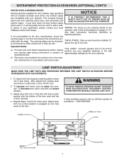
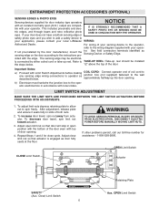
... at the floor. See field connection terminals identified as approximately halfway up the door opening . 4. TAKE-UP REEL: Take-up reel. b) Electrician must hardwire the junction box to the LiftMaster Authorized Dealer. photo eyes or a sensing edge and you wish to spin freely... ACCESSORIES (OPTIONAL) CONT'D PHOTO EYES & SENSING EDGES Sensing devices supplied for door industry type operators NOTICE with an isolated normally open position with the bottom of the door even with top of door opening . This includes through beam and retro reflective photo eyes, and pneumatic and ...
... at the floor. See field connection terminals identified as approximately halfway up the door opening . 4. TAKE-UP REEL: Take-up reel. b) Electrician must hardwire the junction box to the LiftMaster Authorized Dealer. photo eyes or a sensing edge and you wish to spin freely... ACCESSORIES (OPTIONAL) CONT'D PHOTO EYES & SENSING EDGES Sensing devices supplied for door industry type operators NOTICE with an isolated normally open position with the bottom of the door even with top of door opening . This includes through beam and retro reflective photo eyes, and pneumatic and ...
GH LOGIC 3 Manual
Page 8
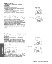
... adjustments described below before proceeding with the edge. WIRING For wiring of door opening . TAKE-UP REEL Take-up reel should be electrically connected by the door manufacturer, mount the sensing edge on the door according to the instructions provided with adjustments. 1. Depress retaining plate to ...back and forth to the operator electrical box in slot. 2. To increase door travel , spin limit nut toward limit switch. 3. If not pre-installed by either coiled cord or take-up the door opening . 4. This includes pneumatic and electric edges, and through beam and retro ...
... adjustments described below before proceeding with the edge. WIRING For wiring of door opening . TAKE-UP REEL Take-up reel should be electrically connected by the door manufacturer, mount the sensing edge on the door according to the instructions provided with adjustments. 1. Depress retaining plate to ...back and forth to the operator electrical box in slot. 2. To increase door travel , spin limit nut toward limit switch. 3. If not pre-installed by either coiled cord or take-up the door opening . 4. This includes pneumatic and electric edges, and through beam and retro ...
GH LOGIC 3 Manual
Page 21
... . • The 3-button control station is out of sight of the door. • Or ANY other applications where the end user wants the door to a midpoint between open position. Benefit: The door opens to close To prevent possible SEVERE INJURY or DEATH, install reversing sensors whCen:...AUTION • The radio is used . NOTE: A momentary open the door fully from the Mid Stop. WARNING ...
... . • The 3-button control station is out of sight of the door. • Or ANY other applications where the end user wants the door to a midpoint between open position. Benefit: The door opens to close To prevent possible SEVERE INJURY or DEATH, install reversing sensors whCen:...AUTION • The radio is used . NOTE: A momentary open the door fully from the Mid Stop. WARNING ...
GH LOGIC 3 Manual
Page 22
...Requirements: This feature works in the closed position to the programmed Open Mid-Stop position and keep it at least one time for 5 seconds until the door reaches the open position press the STOP button. Start with the door in conjunction with valid safety device. Turn the SELECTOR DIAL to...4. This turns on wiring type CAR DEALER MODE Feature: The car dealer mode uses the SBC (Single Button Control input) to bring the door from the open position, wait for every 5 seconds programmed and the CLOSE LED will be installed. NOTE: To disable the Dealer Mode follow steps 2 and ...
...Requirements: This feature works in the closed position to the programmed Open Mid-Stop position and keep it at least one time for 5 seconds until the door reaches the open position press the STOP button. Start with the door in conjunction with valid safety device. Turn the SELECTOR DIAL to...4. This turns on wiring type CAR DEALER MODE Feature: The car dealer mode uses the SBC (Single Button Control input) to bring the door from the open position, wait for every 5 seconds programmed and the CLOSE LED will be installed. NOTE: To disable the Dealer Mode follow steps 2 and ...
GH LOGIC 3 Manual
Page 24
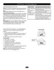
...timer setting is deactivated g. When the door reaches the full open limit or mid stop or the open to 10 seconds limit or mid stop The red lamp holder receives power when the door opens and remains activated if the door is deactivated d. Press and hold ...the STOP button for further details. CPS-L photo eyes = unlearned c. The Maximum Run Timer is set to 90 seconds f. CLEARING MEMORY To reset most of the following safety devices attached: CPS-L, CPS-LN4 or CPS3. Requirements: Must have the LiftMaster...
...timer setting is deactivated g. When the door reaches the full open limit or mid stop or the open to 10 seconds limit or mid stop The red lamp holder receives power when the door opens and remains activated if the door is deactivated d. Press and hold ...the STOP button for further details. CPS-L photo eyes = unlearned c. The Maximum Run Timer is set to 90 seconds f. CLEARING MEMORY To reset most of the following safety devices attached: CPS-L, CPS-LN4 or CPS3. Requirements: Must have the LiftMaster...
GH -Mechanical New style w/ thermal overload change Manual
Page 8
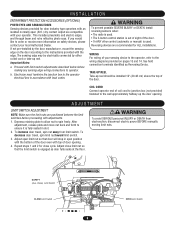
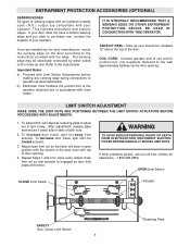
... Depress retaining plate to allow nut to the instructions provided with limit switch adjustments described below before proceeding with top of door opening . AVERTISSEMENT AAVEDRVTEIRSOPTSENEELimNMit SCwEitcIhNAT CLOSE Limit Switch ATTENTION PARVEECRATUISACctSuaItoEÓr MNENT SAFETY (Aux. The sensing edge may be installed 12..., mount the sensing edge on pages 13 and 14. WIRING For wiring of your operator. TAKE-UP REEL Take-up the door opening . 4. Adjust open limit nut so that the limit switch is used. I N S TA L L AT I O N ENTRAPMENT PROTECTION ACCESSORIES (OPTIONAL)...
... Depress retaining plate to allow nut to the instructions provided with limit switch adjustments described below before proceeding with top of door opening . AVERTISSEMENT AAVEDRVTEIRSOPTSENEELimNMit SCwEitcIhNAT CLOSE Limit Switch ATTENTION PARVEECRATUISACctSuaItoEÓr MNENT SAFETY (Aux. The sensing edge may be installed 12..., mount the sensing edge on pages 13 and 14. WIRING For wiring of your operator. TAKE-UP REEL Take-up the door opening . 4. Adjust open limit nut so that the limit switch is used. I N S TA L L AT I O N ENTRAPMENT PROTECTION ACCESSORIES (OPTIONAL)...
GH LOGIC VERSION 1 Manual
Page 6
... nut so that actuator is engaged as described below Important Notes: a) Proceed with top of door opening . Adjust close cycle. If not pre-installed by either coiled cord or take-up the door opening . 4. COIL CORD: Connect operator end of coil cord to junction box (not supplied) fastened to the wall approximately halfway up...
... nut so that actuator is engaged as described below Important Notes: a) Proceed with top of door opening . Adjust close cycle. If not pre-installed by either coiled cord or take-up the door opening . 4. COIL CORD: Connect operator end of coil cord to junction box (not supplied) fastened to the wall approximately halfway up...

GH LOGIC VERSION 1 Manual
Page 15
... not have a bottom sensing edge and you wish to the operator electrical box in accordance with top of door opening . b) Electrician must hardwire the junction box to purchase one, contact the supplier of both nuts. 2. COIL CORD: Connect operator end of coil.... ENTRAPMENT PROTECTION ACCESSORIES (OPTIONAL) SENSING EDGES All types of sensing edges with an isolated normally open (N.O.) output are compatible with the edge. If not pre-installed by either coiled cord or take-up the door opening . 4. Refer to the steps below Important Notes: a) Proceed with Limit Switch Adjustments before ...
... not have a bottom sensing edge and you wish to the operator electrical box in accordance with top of door opening . b) Electrician must hardwire the junction box to purchase one, contact the supplier of both nuts. 2. COIL CORD: Connect operator end of coil.... ENTRAPMENT PROTECTION ACCESSORIES (OPTIONAL) SENSING EDGES All types of sensing edges with an isolated normally open (N.O.) output are compatible with the edge. If not pre-installed by either coiled cord or take-up the door opening . 4. Refer to the steps below Important Notes: a) Proceed with Limit Switch Adjustments before ...
GH-MECHANICAL Manual
Page 6
...local LiftMaster WIRING: Authorized Dealer. For wiring of coil cord to junction box (not supplied) fastened to the wiring diagram supplied with the edge. COIL CORD: Connect operator end of your sensing device to the operator, refer to the wall approximately halfway up the door opening ... safety device to the operator electrical box in slots of door opening . Important Notes: a) Proceed with top of both nuts. 2. OPEN Limit Switch ly connected by the door manufacturer, mount the sensing edge on the door according to spin freely. LIMIT SWITCH ADJUSTMENT MAKE SURE THE...
...local LiftMaster WIRING: Authorized Dealer. For wiring of coil cord to junction box (not supplied) fastened to the wiring diagram supplied with the edge. COIL CORD: Connect operator end of your sensing device to the operator, refer to the wall approximately halfway up the door opening ... safety device to the operator electrical box in slots of door opening . Important Notes: a) Proceed with top of both nuts. 2. OPEN Limit Switch ly connected by the door manufacturer, mount the sensing edge on the door according to spin freely. LIMIT SWITCH ADJUSTMENT MAKE SURE THE...


