
Installation Manual
Page 1
...texting the photo to locate a professional installing dealer in Class I, II, III and IV vehicular slide gate applications. • Visit LiftMaster.com to 71403. CSL24ULTECH COMMERCIAL DC VEHICULAR SLIDE GATE OPERATOR INSTALLATION MANUAL Model CSL24UL LiftMaster 300 Windsor Drive Oak Brook, IL 60523... • THIS PRODUCT IS TO BE INSTALLED AND SERVICED BY A TRAINED GATE SYSTEMS...
...texting the photo to locate a professional installing dealer in Class I, II, III and IV vehicular slide gate applications. • Visit LiftMaster.com to 71403. CSL24ULTECH COMMERCIAL DC VEHICULAR SLIDE GATE OPERATOR INSTALLATION MANUAL Model CSL24UL LiftMaster 300 Windsor Drive Oak Brook, IL 60523... • THIS PRODUCT IS TO BE INSTALLED AND SERVICED BY A TRAINED GATE SYSTEMS...

Installation Manual
Page 2
...16 Step 7 Connect Batteries 18 Step 8 Dual Gate Setup 20 Step 9 Install the Cover 22 ADJUSTMENT 23 Limit and Force Adjustment 23 Obstruction Test 24 PROGRAMMING 25 Remote Controls (Not Provided 25 LiftMaster Internet Gateway (not provided 26 Erase All Codes 26 Erase Limits 26 Constant ... that accompany them carefully. The hazard may come from something mechanical or from electric shock. IMPORTANT NOTE: • BEFORE attempting to install, operate or maintain the operator, you must read and fully understand this Signal Word on the following pages, it will alert you...
...16 Step 7 Connect Batteries 18 Step 8 Dual Gate Setup 20 Step 9 Install the Cover 22 ADJUSTMENT 23 Limit and Force Adjustment 23 Obstruction Test 24 PROGRAMMING 25 Remote Controls (Not Provided 25 LiftMaster Internet Gateway (not provided 26 Erase All Codes 26 Erase Limits 26 Constant ... that accompany them carefully. The hazard may come from something mechanical or from electric shock. IMPORTANT NOTE: • BEFORE attempting to install, operate or maintain the operator, you must read and fully understand this Signal Word on the following pages, it will alert you...

Installation Manual
Page 3
... INSTRUCTIONS. 3 Class IV - The gate MUST reverse on contact with gate controls. Have a qualified service person make repairs to install external monitored entrapment protection devices in each direction; l The entrance is the responsibility of two independent* monitored entrapment protection devices in ...the open direction and two in each entrapment zone l This vehicular slide gate operator will operate only after installation of a minimum of the installer to gate hardware. After adjusting the force or the limit of INJURY or DEATH. Residential Vehicular Gate Operator...
... INSTRUCTIONS. 3 Class IV - The gate MUST reverse on contact with gate controls. Have a qualified service person make repairs to install external monitored entrapment protection devices in each direction; l The entrance is the responsibility of two independent* monitored entrapment protection devices in ...the open direction and two in each entrapment zone l This vehicular slide gate operator will operate only after installation of a minimum of the installer to gate hardware. After adjusting the force or the limit of INJURY or DEATH. Residential Vehicular Gate Operator...

Installation Manual
Page 4
...the possible hazards associated with a separate access opening. The pedestrian access opening and closing to operate the controls. SAFETY Safety Installation Information 1. component part of the reset control shall not cause component. l Vertical Posts l Instructional and Precautionary Signage 4.... of the gate. Vehicular gate systems provide convenience and security. Activation of a gate system. Gate operating system designers, installers and users must be located where the risk of the vehicular gate. 6. A wireless device such as the bystander. ...
...the possible hazards associated with a separate access opening. The pedestrian access opening and closing to operate the controls. SAFETY Safety Installation Information 1. component part of the reset control shall not cause component. l Vertical Posts l Instructional and Precautionary Signage 4.... of the gate. Vehicular gate systems provide convenience and security. Activation of a gate system. Gate operating system designers, installers and users must be located where the risk of the vehicular gate. 6. A wireless device such as the bystander. ...

Installation Manual
Page 5
... of an automated gate system requires replacement, the new gate shall conform to limit travel . Gates shall be designed, constructed and installed such that portion of 6 ft. (1.83 m) above grade, whichever is less, to Class I, Class II and Class III ...1.9 Gates shall be constructed in either lineal direction of an automated vehicular gate, a separate pedestrian gate shall be provided. Gates shall be designed, constructed and installed to the roadway, between a fixed stationary object nearest the roadway, (such as a gate support post) and the gate frame when the gate is disconnected,...
... of an automated gate system requires replacement, the new gate shall conform to limit travel . Gates shall be designed, constructed and installed such that portion of 6 ft. (1.83 m) above grade, whichever is less, to Class I, Class II and Class III ...1.9 Gates shall be constructed in either lineal direction of an automated vehicular gate, a separate pedestrian gate shall be provided. Gates shall be designed, constructed and installed to the roadway, between a fixed stationary object nearest the roadway, (such as a gate support post) and the gate frame when the gate is disconnected,...
Installation Manual
Page 7
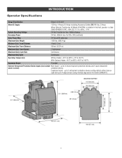
... I, II, III, & IV Main AC Supply 120 Vac, 4 Amps (10 Amps including Accessory Outlets) OR 240 Vac, 2 Amps When Optional Transformer Kit Model 3PHCONV is installed in the field, operator is rated 208/240/480/575 VAC, 4.8/4.2/2.1/1.7 A, 60 Hz, 1 PH System Operating Voltage 24 Vdc Transformer Run / Battery Backup Accessory Power...
... I, II, III, & IV Main AC Supply 120 Vac, 4 Amps (10 Amps including Accessory Outlets) OR 240 Vac, 2 Amps When Optional Transformer Kit Model 3PHCONV is installed in the field, operator is rated 208/240/480/575 VAC, 4.8/4.2/2.1/1.7 A, 60 Hz, 1 PH System Operating Voltage 24 Vdc Transformer Run / Battery Backup Accessory Power...
Installation Manual
Page 8
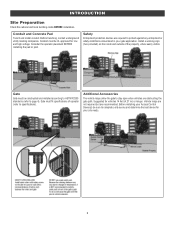
... the gate path. Consider the operator placement BEFORE installing the pad or post. Install a warning sign (two provided) on the inside and outside of operator (refer to specifications). Conduit and Concrete Pad Trench and install conduit. Conduit must be UL approved for vehicles 14...feet (4.27 m) or longer. Gate Gate must fit specifications of the property, where easily visible. Before installing your Access Control Device(s) be constructed and installed according to ASTM F2200 standards (refer to protect against any entrapment or safety conditions encountered in your site ...
... the gate path. Consider the operator placement BEFORE installing the pad or post. Install a warning sign (two provided) on the inside and outside of operator (refer to specifications). Conduit and Concrete Pad Trench and install conduit. Conduit must be UL approved for vehicles 14...feet (4.27 m) or longer. Gate Gate must fit specifications of the property, where easily visible. Before installing your Access Control Device(s) be constructed and installed according to ASTM F2200 standards (refer to protect against any entrapment or safety conditions encountered in your site ...

Installation Manual
Page 9
Types of Installations Standard Installation Rear Installation 9 than 18 inches (46 cm) deep. INSTALLATION l To AVOID damaging gas, power or other underground utility lines, l ALWAYS wear protective gloves and eye protection when changing contact underground utility locating companies BEFORE digging more the battery or working around the battery compartment.
Types of Installations Standard Installation Rear Installation 9 than 18 inches (46 cm) deep. INSTALLATION l To AVOID damaging gas, power or other underground utility lines, l ALWAYS wear protective gloves and eye protection when changing contact underground utility locating companies BEFORE digging more the battery or working around the battery compartment.

Installation Manual
Page 10
Install the electrical conduit. 3. The gate operator should be installed near the back of the gate. Rear Installation 1. Lay out the concrete pad. 2. Standard Installation 1. The gate operator should be installed near the front roller of the gate in the OPEN position. Install the electrical conduit. 3. Pour a concrete pad (reinforced concrete is recommended). 10 Pour a concrete pad (reinforced concrete is recommended). Lay out the concrete pad. 2. INSTALLATION Step 1 Determine Location for Operator Check the national and local building codes before installation.
Install the electrical conduit. 3. The gate operator should be installed near the back of the gate. Rear Installation 1. Lay out the concrete pad. 2. Standard Installation 1. The gate operator should be installed near the front roller of the gate in the OPEN position. Install the electrical conduit. 3. Pour a concrete pad (reinforced concrete is recommended). 10 Pour a concrete pad (reinforced concrete is recommended). Lay out the concrete pad. 2. INSTALLATION Step 1 Determine Location for Operator Check the national and local building codes before installation.

Installation Manual
Page 11
INSTALLATION Step 2 Install the Operator Attach the operator to Accessories). 11 NOTE: An alternative to a concrete pad is to post mount the operator (refer to the concrete pad with appropriate fasteners. The space between the gate and the output sprocket must be installed near the front roller of the gate or near the back of 4 inches (10.2 cm). The gate operator should be a minimum of the gate (in the OPEN position).
INSTALLATION Step 2 Install the Operator Attach the operator to Accessories). 11 NOTE: An alternative to a concrete pad is to post mount the operator (refer to the concrete pad with appropriate fasteners. The space between the gate and the output sprocket must be installed near the front roller of the gate or near the back of 4 inches (10.2 cm). The gate operator should be a minimum of the gate (in the OPEN position).

Installation Manual
Page 12
... (3 m) of chain length. 12 NOTE: The chain should not be level with the idler pulley and parallel to the brackets using the eye bolt hardware. INSTALLATION Step 3 Attach the Chain Standard Installation DO NOT run the operator until instructed. 1. Weld the front bracket in this position. 2.
... (3 m) of chain length. 12 NOTE: The chain should not be level with the idler pulley and parallel to the brackets using the eye bolt hardware. INSTALLATION Step 3 Attach the Chain Standard Installation DO NOT run the operator until instructed. 1. Weld the front bracket in this position. 2.

Installation Manual
Page 13
NOTE: This installation will be too tight or have safety cover. 13 Move the back pulley to the bottom hole in this position. 4. Remove the pin from the ... extra idler pulleys. Route the chain through the operator. 5. Refer to the brackets using the eye bolt hardware. Weld the upper bracket in this position. 3. INSTALLATION Rear Installation DO NOT run the operator until instructed.
NOTE: This installation will be too tight or have safety cover. 13 Move the back pulley to the bottom hole in this position. 4. Remove the pin from the ... extra idler pulleys. Route the chain through the operator. 5. Refer to the brackets using the eye bolt hardware. Weld the upper bracket in this position. 3. INSTALLATION Rear Installation DO NOT run the operator until instructed.
Installation Manual
Page 14
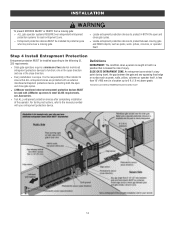
...position that ALL entrapment zones are protected with LiftMaster operators to protect anyone who may come near a moving gate: l ALL gate operator systems REQUIRE two independent entrapment protection systems for each entrapment zone. INSTALLATION To prevent SERIOUS INJURY or DEATH from a...l Test ALL entrapment protection devices after completing installation of the installer to protect in BOTH the open direction and one in the open and close direction. l LiftMaster monitored external entrapment protection devices MUST be installed to meet UL325 requirements, see Accessories. ...
...position that ALL entrapment zones are protected with LiftMaster operators to protect anyone who may come near a moving gate: l ALL gate operator systems REQUIRE two independent entrapment protection systems for each entrapment zone. INSTALLATION To prevent SERIOUS INJURY or DEATH from a...l Test ALL entrapment protection devices after completing installation of the installer to protect in BOTH the open direction and one in the open and close direction. l LiftMaster monitored external entrapment protection devices MUST be installed to meet UL325 requirements, see Accessories. ...

Installation Manual
Page 15
... is sensed during gate opening . This input will be disregarded during gate closing . Only one monitored entrapment protection device may be wired to each input. INSTALLATION Wire Entrapment Protection Devices There are for the open direction. Expansion Board EYE ONLY and COM Open or Close Direction Photoelectric Sensors, the functionality is...
... is sensed during gate opening . This input will be disregarded during gate closing . Only one monitored entrapment protection device may be wired to each input. INSTALLATION Wire Entrapment Protection Devices There are for the open direction. Expansion Board EYE ONLY and COM Open or Close Direction Photoelectric Sensors, the functionality is...

Installation Manual
Page 16
... the remote controls will be reduced and the operator will have to be performed until disconnecting the electrical power (AC l DO NOT install ANY wiring or attempt to your application. l ALL power wiring should be made by a qualified individual. For dual gate applications, ...power disconnect should cut the ground wire too short, break it, or destroy its integrity, replace it with national and local electrical codes. Install the earth ground rod within 3 feet (.9 m) of adequate capacity. Operator labeled. SOLAR APPLICATIONS: For solar applications refer to each operator...
... the remote controls will be reduced and the operator will have to be performed until disconnecting the electrical power (AC l DO NOT install ANY wiring or attempt to your application. l ALL power wiring should be made by a qualified individual. For dual gate applications, ...power disconnect should cut the ground wire too short, break it, or destroy its integrity, replace it with national and local electrical codes. Install the earth ground rod within 3 feet (.9 m) of adequate capacity. Operator labeled. SOLAR APPLICATIONS: For solar applications refer to each operator...

Installation Manual
Page 17
... or better electrical, mechanical, and flammability ratings. 240 VAC only The accessory outlet is now set for 240 Vac operation. 120 VAC and 240 VAC 1. INSTALLATION All control wiring used with the 240 Vac option. 1.
... or better electrical, mechanical, and flammability ratings. 240 VAC only The accessory outlet is now set for 240 Vac operation. 120 VAC and 240 VAC 1. INSTALLATION All control wiring used with the 240 Vac option. 1.

Installation Manual
Page 18
... AC power switch on the operator will power up the control board. This will turn off AC power to the negative (-) terminal of the battery. 6. INSTALLATION AC power switch The AC Power switch on the operator. 18
... AC power switch on the operator will power up the control board. This will turn off AC power to the negative (-) terminal of the battery. 6. INSTALLATION AC power switch The AC Power switch on the operator. 18

Installation Manual
Page 19
... of the black (-) wire from the J15 plug as shown. 5. NOTE: You may see a small spark when plugging the J15 plug into the board. 19 INSTALLATION 33AH battery The batteries are for battery backup or solar installation. The batteries are charged in the circuit by the integrated transformer.
... of the black (-) wire from the J15 plug as shown. 5. NOTE: You may see a small spark when plugging the J15 plug into the board. 19 INSTALLATION 33AH battery The batteries are for battery backup or solar installation. The batteries are charged in the circuit by the integrated transformer.

Installation Manual
Page 20
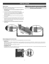
... to your application. Press and release the LEARN button again on the primary operator. Press and release the LEARN button again on the second operator. INSTALLATION Step 8 Dual gate setup There are set on either operator. The yellow NETWORK LED will time out of programming mode after 180 seconds. 3. Wireless setup...
... to your application. Press and release the LEARN button again on the primary operator. Press and release the LEARN button again on the second operator. INSTALLATION Step 8 Dual gate setup There are set on either operator. The yellow NETWORK LED will time out of programming mode after 180 seconds. 3. Wireless setup...
Installation Manual
Page 21
... TYPE (SHIELDED TWISTED PAIR CABLE) 22AWG up to 200 feet (61 m) 18AWG - 200-1000 feet (61-305 m) Wire must be the first to Com Link B). INSTALLATION Wired setup Before digging, contact local underground utility locating companies. Connect ALL power to the secondary gate operator's control board. 5. SLIDE GATE APPLICATIONS: Not applicable...
... TYPE (SHIELDED TWISTED PAIR CABLE) 22AWG up to 200 feet (61 m) 18AWG - 200-1000 feet (61-305 m) Wire must be the first to Com Link B). INSTALLATION Wired setup Before digging, contact local underground utility locating companies. Connect ALL power to the secondary gate operator's control board. 5. SLIDE GATE APPLICATIONS: Not applicable...


