BG790 Manual
Page 1
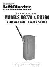
OWNER'S MANUAL MODELS BG770 & BG790 VEHICULAR BARRIER GATE OPERATOR MODELS BG770 AND BG790 ARE FOR VEHICULAR PASSAGE GATES ONLY AND ARE NOT INTENDED FOR PEDESTRIAN PASSAGE GATE USE
OWNER'S MANUAL MODELS BG770 & BG790 VEHICULAR BARRIER GATE OPERATOR MODELS BG770 AND BG790 ARE FOR VEHICULAR PASSAGE GATES ONLY AND ARE NOT INTENDED FOR PEDESTRIAN PASSAGE GATE USE
BG790 Manual
Page 2
... intended to highlight certain safety related issues. Read the warnings carefully. Model BG790 18 Repair Parts - Model BG770 16 Repair Parts - Model BG770 17 Illustrated Parts - Model BG790 19 MAINTENANCE Limited Bearing Lubrication 20 Grease Turnbuckle 20 WIRING DIAGRAMS Single Phase ...Vehicle Detectors 12 Radio Controls 12 Card Readers, Keypads or Other 12 Mounting Location 12 OPERATING INSTRUCTIONS Electrical Operation 13 Manual Operation 13 TROUBLESHOOTING Power 14 Accessories 14 Primary Voltage Circuit 15 Low Voltage Circuit 15 General Reference Information 15 REPAIR...
... intended to highlight certain safety related issues. Read the warnings carefully. Model BG790 18 Repair Parts - Model BG770 16 Repair Parts - Model BG770 17 Illustrated Parts - Model BG790 19 MAINTENANCE Limited Bearing Lubrication 20 Grease Turnbuckle 20 WIRING DIAGRAMS Single Phase ...Vehicle Detectors 12 Radio Controls 12 Card Readers, Keypads or Other 12 Mounting Location 12 OPERATING INSTRUCTIONS Electrical Operation 13 Manual Operation 13 TROUBLESHOOTING Power 14 Accessories 14 Primary Voltage Circuit 15 Low Voltage Circuit 15 General Reference Information 15 REPAIR...
BG790 Manual
Page 3
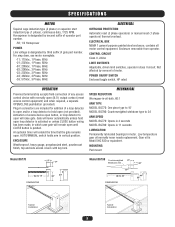
...-23; 230Vac, 3 Phase. 60Hz -43; 460Vac, 3 Phase, 60Hz -53; 575Vac, 3 Phase, 60Hz ELECTRICAL OVERLOAD PROTECTION Automatic reset (3 phase operators) or manual reset (1 phase operators) thermal overload. ELECTRICAL BOX NEMA 1 general purpose painted steel enclosure, contains all motor control equipment. CONTROL CIRCUIT Class II, 24Vac LIMIT SWITCHES... which case gate will remain open (not provided). An optional timer will raise gate. MOUNTING Pad mount Model BG770 17" 17" Up to 15' DIMENSIONS 35" 44" Model BG790 Counterweighted 17" Wishbone Arm 17" Up to 24' ARM ...
...-23; 230Vac, 3 Phase. 60Hz -43; 460Vac, 3 Phase, 60Hz -53; 575Vac, 3 Phase, 60Hz ELECTRICAL OVERLOAD PROTECTION Automatic reset (3 phase operators) or manual reset (1 phase operators) thermal overload. ELECTRICAL BOX NEMA 1 general purpose painted steel enclosure, contains all motor control equipment. CONTROL CIRCUIT Class II, 24Vac LIMIT SWITCHES... which case gate will remain open (not provided). An optional timer will raise gate. MOUNTING Pad mount Model BG770 17" 17" Up to 15' DIMENSIONS 35" 44" Model BG790 Counterweighted 17" Wishbone Arm 17" Up to 24' ARM ...
BG790 Manual
Page 4
... pedestrian access opening . Outdoor or easily accessible controls shall have a security feature to operate the controls. A minimum of non-contact sensor for vehicles. Reference owner's manual regarding placement of two (2) WARNING SIGNS shall be incorporated into public access areas. 7. Care shall be properly installed and work freely in both inside and...
... pedestrian access opening . Outdoor or easily accessible controls shall have a security feature to operate the controls. A minimum of non-contact sensor for vehicles. Reference owner's manual regarding placement of two (2) WARNING SIGNS shall be incorporated into public access areas. 7. Care shall be properly installed and work freely in both inside and...
BG790 Manual
Page 5
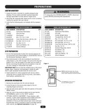
... amperage to components may not run . Damage claims MUST be filed with the standard unit. See chart on page 12). 5 AUTO/MANUAL switch should be in panel shown below. Refer to gate nameplate located inside service cover) accurately matches the operator that selected gate location ...the cover of run at the site, do so now. PREPARATIONS CARTON INVENTORY 1. WARNING To reduce the risk of the power ON/OFF switch. 4. MODEL BG770 PACKING LIST PART NUMBER DESCRIPTION QTY 02-102 Open/Close Push Button 1 07-8007 Gate Arm Hub 1 10-8007M Gate Bracket 1 80-G0187 Key, ...
... amperage to components may not run . Damage claims MUST be filed with the standard unit. See chart on page 12). 5 AUTO/MANUAL switch should be in panel shown below. Refer to gate nameplate located inside service cover) accurately matches the operator that selected gate location ...the cover of run at the site, do so now. PREPARATIONS CARTON INVENTORY 1. WARNING To reduce the risk of the power ON/OFF switch. 4. MODEL BG770 PACKING LIST PART NUMBER DESCRIPTION QTY 02-102 Open/Close Push Button 1 07-8007 Gate Arm Hub 1 10-8007M Gate Bracket 1 80-G0187 Key, ...
BG790 Manual
Page 7
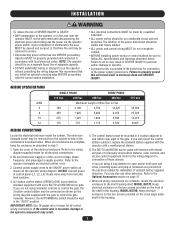
...Be sure that power supply is provided as shown on the wiring diagram supplied with every BG770 and BG790 barrier gate. DO NOT connect power at the fuse box BEFORE proceeding. However, the AUTO/MANUAL switch should be on a dedicated circuit and well protected. If the control wire is provided... on page 12. 7. Connect power supply wires to the ON/OFF power switch as standard equipment with the gate to control the gate manually. When all electrical connections. 2. Failure to do so may be properly grounded and connected in accordance with almost all control wiring connections. ...
...Be sure that power supply is provided as shown on the wiring diagram supplied with every BG770 and BG790 barrier gate. DO NOT connect power at the fuse box BEFORE proceeding. However, the AUTO/MANUAL switch should be on a dedicated circuit and well protected. If the control wire is provided... on page 12. 7. Connect power supply wires to the ON/OFF power switch as standard equipment with the gate to control the gate manually. When all electrical connections. 2. Failure to do so may be properly grounded and connected in accordance with almost all control wiring connections. ...
BG790 Manual
Page 13
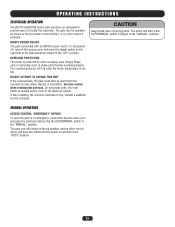
... ACCESS CONTROL "EMERGENCY" BYPASS To open the electrical cabinet. Flip the AUTO/MANUAL switch to provide years of the main electrical cabinet to the "MANUAL" position. OPERATING INSTRUCTIONS ELECTRICAL OPERATION The BG770 and BG790 barrier gate operators are designed to the "MANUAL" position. Exercise caution when resetting the overload. If after resetting, the overload...
... ACCESS CONTROL "EMERGENCY" BYPASS To open the electrical cabinet. Flip the AUTO/MANUAL switch to provide years of the main electrical cabinet to the "MANUAL" position. OPERATING INSTRUCTIONS ELECTRICAL OPERATION The BG770 and BG790 barrier gate operators are designed to the "MANUAL" position. Exercise caution when resetting the overload. If after resetting, the overload...
BG790 Manual
Page 15
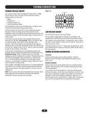
... Are there unprotected pinch points? If yes, then correct. Is it should be replaced. If the first two check out okay, then manually disconnect the operator from one for it be in either the full open or close ). Disconnect Power! Repeat this circuit that it at ...replaced. GENERAL REFERENCE INFORMATION THE GATE Double check the gate and its related hardware. Did the operator run in the controller (Model BG770 uses a manual reset overload). If it is the incoming power. you will require technical assistance, contact your local distributor or dealer. It is suspected...
... Are there unprotected pinch points? If yes, then correct. Is it should be replaced. If the first two check out okay, then manually disconnect the operator from one for it be in either the full open or close ). Disconnect Power! Repeat this circuit that it at ...replaced. GENERAL REFERENCE INFORMATION THE GATE Double check the gate and its related hardware. Did the operator run in the controller (Model BG770 uses a manual reset overload). If it is the incoming power. you will require technical assistance, contact your local distributor or dealer. It is suspected...
BG790 Manual
Page 20
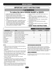
...LIMITED BEARING LUBRICATION The barrier gates require very little in the area. Motor and shaft bearing normally should always be performed by a LiftMaster professional. 10.SAVE THESE INSTRUCTIONS. ALWAYS keep people and objects away from children. 3. ALL maintenance MUST be performed anytime a malfunction...silicone spray. • When servicing, please do some voltage readings of the operator. Failure to the site. Read the owner's manual. NO ONE SHOULD CROSS THE PATH OF THE MOVING GATE. 4. Have a qualified service person make sure it should be reset ...
...LIMITED BEARING LUBRICATION The barrier gates require very little in the area. Motor and shaft bearing normally should always be performed by a LiftMaster professional. 10.SAVE THESE INSTRUCTIONS. ALWAYS keep people and objects away from children. 3. ALL maintenance MUST be performed anytime a malfunction...silicone spray. • When servicing, please do some voltage readings of the operator. Failure to the site. Read the owner's manual. NO ONE SHOULD CROSS THE PATH OF THE MOVING GATE. 4. Have a qualified service person make sure it should be reset ...
BG790 Manual
Page 21
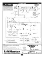
... (BK) 0/L (BK) (BK) IR SEE NOTE 2 (BK) 115V ONLY (BK) (W) CL 43 4 OP 3 2 OP 1 6 CL 5 (OR) 230V ONLY (YEL) (YEL) AUTO/MANUAL OPEN OPEN LOOP-PRESENCE (GN) (W) J3-4 J3-6 SENSING EDGE (OPTIONAL) AUX. (W) CLOSE L/S (GY) 3 7 1 (OR) R1 (GN) R2 (GN) 5 (OR) 14 OP 13 (OR... CLOSE IS USED. 2) REMOVE JUMPER TO CAUSE GATE ARM TO CLOSE IMMEDIATELY UNLESS HOLD OPEN LOOP IS ACTIVATED. (OR) OP 56 1 CL 2 (1 of rating. FOR BG770, INTERCHANGE GREEN AND RED WIRES (GN) BR (BK) (W) BR (R) 115V MOTOR CONNECTION YW 4 2 8 BK 5 OR BL 1 3 O/L SEE NOTE 4 (GN) W BR 4 (BK...
... (BK) 0/L (BK) (BK) IR SEE NOTE 2 (BK) 115V ONLY (BK) (W) CL 43 4 OP 3 2 OP 1 6 CL 5 (OR) 230V ONLY (YEL) (YEL) AUTO/MANUAL OPEN OPEN LOOP-PRESENCE (GN) (W) J3-4 J3-6 SENSING EDGE (OPTIONAL) AUX. (W) CLOSE L/S (GY) 3 7 1 (OR) R1 (GN) R2 (GN) 5 (OR) 14 OP 13 (OR... CLOSE IS USED. 2) REMOVE JUMPER TO CAUSE GATE ARM TO CLOSE IMMEDIATELY UNLESS HOLD OPEN LOOP IS ACTIVATED. (OR) OP 56 1 CL 2 (1 of rating. FOR BG770, INTERCHANGE GREEN AND RED WIRES (GN) BR (BK) (W) BR (R) 115V MOTOR CONNECTION YW 4 2 8 BK 5 OR BL 1 3 O/L SEE NOTE 4 (GN) W BR 4 (BK...
BG790 Manual
Page 22
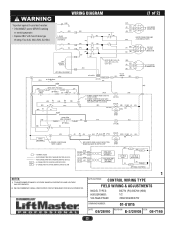
... COLOR: 208V-(R), 230V-(OR), 480-(VT), 575V-(GY) (GN) (BL) 1 (R) 2 (W) (BL) 3 J 575V MOTOR CONNECTION J (OPTIONAL EQUIPMENT) (YEL) 4 (YEL) AUTO/MANUAL O/L IN SEE NOTE 1 (BL) MOTOR (OR) FUSE 3.2A J1 J2 24V SEC. (W) OPEN (OR) (GN) OPEN LOOP-PRESENCE (W) J3-4 J3-6 SENSING EDGE (OPTIONAL) AUX.... A DEDICATED CIRCUIT BREAKER FOR EACH OPERATOR. 1 APPLICATIONS: CONTROL WIRING TYPE FIELD WIRING & ADJUSTMENTS MODEL TYPES: HORSEPOWER: VOLTAGE/PHASE: BG770 (PG) BG790 (HBG) 1/2 208/230/480/575V DRAWING NUMBER: 01-G1015 DATE: 08/28/00 REVISION: E-3/20/08 ECN: 08-7165 ...
... COLOR: 208V-(R), 230V-(OR), 480-(VT), 575V-(GY) (GN) (BL) 1 (R) 2 (W) (BL) 3 J 575V MOTOR CONNECTION J (OPTIONAL EQUIPMENT) (YEL) 4 (YEL) AUTO/MANUAL O/L IN SEE NOTE 1 (BL) MOTOR (OR) FUSE 3.2A J1 J2 24V SEC. (W) OPEN (OR) (GN) OPEN LOOP-PRESENCE (W) J3-4 J3-6 SENSING EDGE (OPTIONAL) AUX.... A DEDICATED CIRCUIT BREAKER FOR EACH OPERATOR. 1 APPLICATIONS: CONTROL WIRING TYPE FIELD WIRING & ADJUSTMENTS MODEL TYPES: HORSEPOWER: VOLTAGE/PHASE: BG770 (PG) BG790 (HBG) 1/2 208/230/480/575V DRAWING NUMBER: 01-G1015 DATE: 08/28/00 REVISION: E-3/20/08 ECN: 08-7165 ...
BG790 Manual
Page 23
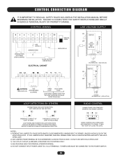
... BUTTON IS USED. CONTROL WIRING LINE VOLTAGE SUPPLY OPEN BUTTON OR OTHER OPEN CONTROL SEE NOTE #1 SENSING EDGE CLOSE BUTTON SEE NOTE #2 ELECTRICAL CABINET MANUAL OPEN SEE NOTE #2 WARNING 115V (SEE NOTE #5) ACCESSORIES (0.2A MAX) OPEN LOOP HOLD OPEN LOOP LOOP WIRE CONNECTIONS FOR FACTORY SUPPLIED (PLUG-IN... CONNECT INPUT POWER LINES TO L1 & L2 TERMINALS. CONTROL CONNECTION DIAGRAM IT IS IMPORTANT TO READ ALL SAFETY RULES INCLUDED IN THE INSTALLATION MANUAL BEFORE BEGINNING INSTALLATION. POWER LINES MUST BE CONNECTED TO THE POWER SWITCH. 23 IT WILL NOT STOP OR CLOSE THE GATE.
... BUTTON IS USED. CONTROL WIRING LINE VOLTAGE SUPPLY OPEN BUTTON OR OTHER OPEN CONTROL SEE NOTE #1 SENSING EDGE CLOSE BUTTON SEE NOTE #2 ELECTRICAL CABINET MANUAL OPEN SEE NOTE #2 WARNING 115V (SEE NOTE #5) ACCESSORIES (0.2A MAX) OPEN LOOP HOLD OPEN LOOP LOOP WIRE CONNECTIONS FOR FACTORY SUPPLIED (PLUG-IN... CONNECT INPUT POWER LINES TO L1 & L2 TERMINALS. CONTROL CONNECTION DIAGRAM IT IS IMPORTANT TO READ ALL SAFETY RULES INCLUDED IN THE INSTALLATION MANUAL BEFORE BEGINNING INSTALLATION. POWER LINES MUST BE CONNECTED TO THE POWER SWITCH. 23 IT WILL NOT STOP OR CLOSE THE GATE.


