

8587 Manual
Page 1
... for installation instructions. ELITE Series Chain Drive Garage Door Opener Model 8587 - 3/4 hp FOR RESIDENTIAL USE ONLY ■ Please read this manual and the enclosed safety materials carefully! ■ Fasten the manual near the garage door after installation. ■ The door...32 Troubleshooting 33-34 Accessories 35 Warranty 36 Repair Parts 37-38 www.liftmaster.com The Chamberlain Group, Inc. 845 Larch Avenue Elmhurst, Illinois 60126-1196 Date of your garage door opener. ■ This garage door opener is ONLY compatible with MyQ® and Security✚ 2.0™ accessories....
... for installation instructions. ELITE Series Chain Drive Garage Door Opener Model 8587 - 3/4 hp FOR RESIDENTIAL USE ONLY ■ Please read this manual and the enclosed safety materials carefully! ■ Fasten the manual near the garage door after installation. ■ The door...32 Troubleshooting 33-34 Accessories 35 Warranty 36 Repair Parts 37-38 www.liftmaster.com The Chamberlain Group, Inc. 845 Larch Avenue Elmhurst, Illinois 60126-1196 Date of your garage door opener. ■ This garage door opener is ONLY compatible with MyQ® and Security✚ 2.0™ accessories....

8587 Manual
Page 2
...or right of the door. Lift the door halfway up. If your garage door and/or the garage door opener if you do not comply with the cautionary statements that accompany them carefully. An unbalanced garage door may be installed above the center of the door center. When ... and remove ALL ropes connected to garage door BEFORE installation and operating garage door opener to avoid entanglement. 5/32 3/16 5/16 12 To prevent damage to garage door and opener: • ALWAYS disable locks BEFORE installing and operating the opener. • ONLY operate garage door opener at 120 V, 60 Hz to ...
...or right of the door. Lift the door halfway up. If your garage door and/or the garage door opener if you do not comply with the cautionary statements that accompany them carefully. An unbalanced garage door may be installed above the center of the door center. When ... and remove ALL ropes connected to garage door BEFORE installation and operating garage door opener to avoid entanglement. 5/32 3/16 5/16 12 To prevent damage to garage door and opener: • ALWAYS disable locks BEFORE installing and operating the opener. • ONLY operate garage door opener at 120 V, 60 Hz to ...

8587 Manual
Page 3
...white and white/black wire attached: Sending Sensor (1), Receiving Sensor (1) Safety Sensor Brackets (2), and Extension Brackets (2) P. GARAGE DOOR OPENER ASSEMBLY A. Header bracket F. Curved door arm I 3 880LM Smart Control Panel® 895MAX Remote Control Hardware Assembly ... (2) Chain Spreader Hardware Screw #8-32 x 3/8" (2) Rail Hardware Washered Bolts and Lock Washer [mounted in this manual are not included in the top of the garage door opener] Installation Hex Bolt 5/16"-18 x 7/8" (4) Lag Screw 5/16"-9 x 1-5/8" (2) Lag Screw 5/16"-18 x 1-5/8" (2) Clevis Pin 5/16" x ...
...white and white/black wire attached: Sending Sensor (1), Receiving Sensor (1) Safety Sensor Brackets (2), and Extension Brackets (2) P. GARAGE DOOR OPENER ASSEMBLY A. Header bracket F. Curved door arm I 3 880LM Smart Control Panel® 895MAX Remote Control Hardware Assembly ... (2) Chain Spreader Hardware Screw #8-32 x 3/8" (2) Rail Hardware Washered Bolts and Lock Washer [mounted in this manual are not included in the top of the garage door opener] Installation Hex Bolt 5/16"-18 x 7/8" (4) Lag Screw 5/16"-9 x 1-5/8" (2) Lag Screw 5/16"-18 x 1-5/8" (2) Clevis Pin 5/16" x ...

8587 Manual
Page 4
...the rail to the garage door opener To avoid SERIOUS damage to garage door opener, use with screws. 1.6 Guide the chain around the garage door opener sprocket. 1.5 Attach the chain spreader to the garage door opener with regular doors. HARDWARE Washered Bolt 5/16"-18x1/2" (Mounted in the garage door opener) Lock Nut (Mounted ... House Doors and the 8tooth sprocket is for use ONLY those bolts/fasteners mounted in the garage door opener) NOTE: ONLY use the bolts removed from the top of the opener. Chain Spreader Washered Bolt 5/16"-18x1/2" Lock Nut Hex Screws 8-32x1" Washers 6-Tooth ...
...the rail to the garage door opener To avoid SERIOUS damage to garage door opener, use with screws. 1.6 Guide the chain around the garage door opener sprocket. 1.5 Attach the chain spreader to the garage door opener with regular doors. HARDWARE Washered Bolt 5/16"-18x1/2" (Mounted in the garage door opener) Lock Nut (Mounted ... House Doors and the 8tooth sprocket is for use ONLY those bolts/fasteners mounted in the garage door opener) NOTE: ONLY use the bolts removed from the top of the opener. Chain Spreader Washered Bolt 5/16"-18x1/2" Lock Nut Hex Screws 8-32x1" Washers 6-Tooth ...
8587 Manual
Page 5
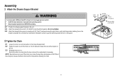
...Screw #8-32x3/8" Washerd Bolt 5/16"-18x1/2" 1/2" 5 Assembly 2 Attach the Chassis Support Bracket To avoid possible SERIOUS INJURY to finger from moving garage door opener: • ALWAYS keep hand clear of the rail. 3.3 Re-tighten the inner nut. Complete the connection by inserting a 5/16"-18x1/2" ... Sprocket noise can result if the chain is a 1/2 inch above the base of the rail at the midpoint of sprocket while operating opener. • Securely attach sprocket cover BEFORE operating. 2.1 Position the chassis support bracket on the trolley threaded shaft. 3.2 Tighten the outer...
...Screw #8-32x3/8" Washerd Bolt 5/16"-18x1/2" 1/2" 5 Assembly 2 Attach the Chassis Support Bracket To avoid possible SERIOUS INJURY to finger from moving garage door opener: • ALWAYS keep hand clear of the rail. 3.3 Re-tighten the inner nut. Complete the connection by inserting a 5/16"-18x1/2" ... Sprocket noise can result if the chain is a 1/2 inch above the base of the rail at the midpoint of sprocket while operating opener. • Securely attach sprocket cover BEFORE operating. 2.1 Position the chassis support bracket on the trolley threaded shaft. 3.2 Tighten the outer...

8587 Manual
Page 6
...ANY service or maintenance. 14. Install garage door opener ONLY on a one -piece or swinging garage doors. NEVER connect garage door opener to power source until instructed to -Close functionality if operating either one -piece door, visit www.liftmaster.com for installation instructions. 6 Door ...other hardware MUST be enabled ONLY when operating a sectional door. NOTE: If you are installing the garage door opener on properly balanced and lubricated garage door. Installation IMPORTANT INSTALLATION INSTRUCTIONS WARNING To reduce the risk of installation, test safety reversal system. ...
...ANY service or maintenance. 14. Install garage door opener ONLY on a one -piece or swinging garage doors. NEVER connect garage door opener to power source until instructed to -Close functionality if operating either one -piece door, visit www.liftmaster.com for installation instructions. 6 Door ...other hardware MUST be enabled ONLY when operating a sectional door. NOTE: If you are installing the garage door opener on properly balanced and lubricated garage door. Installation IMPORTANT INSTALLATION INSTRUCTIONS WARNING To reduce the risk of installation, test safety reversal system. ...

8587 Manual
Page 7
If you need to install the header bracket on a 2x4 (on a one-piece door, visit www.liftmaster.com for ceiling installation. NOTE: If the total number of inches exceeds the height available in the way; DO NOT install header bracket over drywall. ... lag screws (not provided) to securely fasten the 2x4 to structural supports. 1.3 Open your door to loosen, move or adjust garage door, springs, cables, pulleys, brackets, or their hardware, ALL of which are installing the garage door opener on wall or ceiling), use the maximum height possible, or refer to page 8 for installation ...
If you need to install the header bracket on a 2x4 (on a one-piece door, visit www.liftmaster.com for ceiling installation. NOTE: If the total number of inches exceeds the height available in the way; DO NOT install header bracket over drywall. ... lag screws (not provided) to securely fasten the 2x4 to structural supports. 1.3 Open your door to loosen, move or adjust garage door, springs, cables, pulleys, brackets, or their hardware, ALL of which are installing the garage door opener on wall or ceiling), use the maximum height possible, or refer to page 8 for installation ...

8587 Manual
Page 9
... between the rail and the door. Ring Fastener Clevis Pin 5/16" X 2-3/4" HARDWARE Clevis Pin 5/16" x 2-3/4" Ring Fastener 4 Position the garage door opener To prevent damage to disconnect the inner and outer trolley. 3 Attach the rail to the header bracket 3.1 Align the rail with the ring fastener..... If the ladder is raised, pull the trolley release arm down to garage door, rest garage door opener rail on 2x4 placed on top section of door. 4.1 Remove the packing material and lift the garage door opener onto a ladder. Insert the clevis pin through the holes in the header...
... between the rail and the door. Ring Fastener Clevis Pin 5/16" X 2-3/4" HARDWARE Clevis Pin 5/16" x 2-3/4" Ring Fastener 4 Position the garage door opener To prevent damage to disconnect the inner and outer trolley. 3 Attach the rail to the header bracket 3.1 Align the rail with the ring fastener..... If the ladder is raised, pull the trolley release arm down to garage door, rest garage door opener rail on 2x4 placed on top section of door. 4.1 Remove the packing material and lift the garage door opener onto a ladder. Insert the clevis pin through the holes in the header...

8587 Manual
Page 10
... and fastening hardware are shown. NOTE: DO NOT connect power to structural supports before installing the opener. Instructions below are for attaching the garage door opener directly to structural supports. 5.1 Measure the distance from a falling garage door opener, fasten it SECURELY to structural supports of each side of the motor unit to the structural support...
... and fastening hardware are shown. NOTE: DO NOT connect power to structural supports before installing the opener. Instructions below are for attaching the garage door opener directly to structural supports. 5.1 Measure the distance from a falling garage door opener, fasten it SECURELY to structural supports of each side of the motor unit to the structural support...

8587 Manual
Page 11
... Rotate the lens up . Mount the emergency release within reach, but at least 1 inch (2.5 cm) from a falling garage door: • If possible, use emergency release handle to the opener: • DO NOT use halogen bulbs. • DO NOT use incandescent bulbs larger than 26W (100W equivalent). To ... LED bulbs as these may reduce the range or performance of all vehicles to pull door open door falling rapidly and/or unexpectedly. • NEVER use emergency release handle unless garage doorway is right side up to close. 7 Attach the emergency release rope and handle To...
... Rotate the lens up . Mount the emergency release within reach, but at least 1 inch (2.5 cm) from a falling garage door: • If possible, use emergency release handle to the opener: • DO NOT use halogen bulbs. • DO NOT use incandescent bulbs larger than 26W (100W equivalent). To ... LED bulbs as these may reduce the range or performance of all vehicles to pull door open door falling rapidly and/or unexpectedly. • NEVER use emergency release handle unless garage doorway is right side up to close. 7 Attach the emergency release rope and handle To...

8587 Manual
Page 12
...Inside Edge of Door or Reinforcement Board UP Vertical Centerline of the clevis pin and door arm. The best solution is needed for an opener installation door reinforcement kit. proceed to two or three vertical supports. Note correct UP placement, as stamped inside the bracket. 1/4" - 14x... bracket 2"-4" (5-10 cm) below the top edge of the door, OR directly below FIGURE 4 any structural support across the top of Garage Door • Alternately, use on the previously marked vertical centerline used to create a U-shaped support. Contact your door manufacturer for use two...
...Inside Edge of Door or Reinforcement Board UP Vertical Centerline of the clevis pin and door arm. The best solution is needed for an opener installation door reinforcement kit. proceed to two or three vertical supports. Note correct UP placement, as stamped inside the bracket. 1/4" - 14x... bracket 2"-4" (5-10 cm) below the top edge of the door, OR directly below FIGURE 4 any structural support across the top of Garage Door • Alternately, use on the previously marked vertical centerline used to create a U-shaped support. Contact your door manufacturer for use two...

8587 Manual
Page 13
... trolley by 9.2 Attach the straight door arm to the door bracket using the trolley release arm is activated. Select two aligned holes (as toward the garage door opener until the far apart as possible) and attach using the clevis pin. trolley will re-engage automatically when the... garage door opener is horizontal. Trolley release arm 13 Nut 5/16" - 18 Lock Washer 5/16" Hex Bolt 5/16" - 18 x 7/8" If the straight door arm is hanging down too ...
... trolley by 9.2 Attach the straight door arm to the door bracket using the trolley release arm is activated. Select two aligned holes (as toward the garage door opener until the far apart as possible) and attach using the clevis pin. trolley will re-engage automatically when the... garage door opener is horizontal. Trolley release arm 13 Nut 5/16" - 18 Lock Washer 5/16" Hex Bolt 5/16" - 18 x 7/8" If the straight door arm is hanging down too ...

8587 Manual
Page 14
..." (11 mm) PRE-WIRED INSTALLATIONS: Choose Wall any other Security+ 2.0™ door controls. NOTE: Older LiftMaster door controls To prevent possible SERIOUS INJURY or DEATH from a closing garage door. Screw 6ABx1" Screw 6-32x1" HARDWARE Drywall Anchors NOTE: For gang box installations it can be seen clearly...door at • NEVER permit children to operate or play with up to cross path of moving parts of the door. Your garage door opener is NOT connected BEFORE installing door control. • Connect ONLY to 12 VOLT low voltage wires. accessories, see page 35....
..." (11 mm) PRE-WIRED INSTALLATIONS: Choose Wall any other Security+ 2.0™ door controls. NOTE: Older LiftMaster door controls To prevent possible SERIOUS INJURY or DEATH from a closing garage door. Screw 6ABx1" Screw 6-32x1" HARDWARE Drywall Anchors NOTE: For gang box installations it can be seen clearly...door at • NEVER permit children to operate or play with up to cross path of moving parts of the door. Your garage door opener is NOT connected BEFORE installing door control. • Connect ONLY to 12 VOLT low voltage wires. accessories, see page 35....

8587 Manual
Page 15
...-wired installations). RED WHITE WHITE GREY PRE-WIRED INSTALLATIONS: When wiring the door control to the garage door opener make sure you use the same wires that are connected to the garage door opener. Install the Door Control k 1.5 Position the bottom hole of the door control over the screw... place. Attach the top screw. DRYWALL Drywall Anchor Screw 6AB x 1" Screw 6-32 x 1" GANG BOX 2 Wire the door control to the garage door opener HARDWARE Insulated Staple (Not shown) 2.1 Run the white and red/white wire from the terminal, push in the tab with the staples (not applicable...
...-wired installations). RED WHITE WHITE GREY PRE-WIRED INSTALLATIONS: When wiring the door control to the garage door opener make sure you use the same wires that are connected to the garage door opener. Install the Door Control k 1.5 Position the bottom hole of the door control over the screw... place. Attach the top screw. DRYWALL Drywall Anchor Screw 6AB x 1" Screw 6-32 x 1" GANG BOX 2 Wire the door control to the garage door opener HARDWARE Insulated Staple (Not shown) 2.1 Run the white and red/white wire from the terminal, push in the tab with the staples (not applicable...

8587 Manual
Page 17
...an invisible light beam to the garage door opener BEFORE installing the safety reversing sensor. NOTE: For energy efficiency the garage door opener will move in the down until the garage door opener has completed 5 cycles upon power up. The sleep mode shuts the garage door opener down direction. as the light ...6" (15 cm) max. To prevent SERIOUS INJURY or DEATH from closing , the door will stop and reverse to the full open position, and the garage door opener lights will turn off the sensor LEDs will flash 10 times. The sleep mode is fully closed. Safety Reversing Sensor 6" (15...
...an invisible light beam to the garage door opener BEFORE installing the safety reversing sensor. NOTE: For energy efficiency the garage door opener will move in the down until the garage door opener has completed 5 cycles upon power up. The sleep mode shuts the garage door opener down direction. as the light ...6" (15 cm) max. To prevent SERIOUS INJURY or DEATH from closing , the door will stop and reverse to the full open position, and the garage door opener lights will turn off the sensor LEDs will flash 10 times. The sleep mode is fully closed. Safety Reversing Sensor 6" (15...

8587 Manual
Page 19
...black wires together. 2.3A Insert the white wires into the grey terminal on both sensors to the already has wires installed for the safety reversing garage door opener. Carriage Bolt 1/4" - 20 x 1/2" 1.4C Insert the bolt through the hole in the tab with a screwdriver tip. To insert or remove... both sensors should point toward each other. RED WHITE WHITE GREY Insulated Staple (Not shown) 7/16" (11 mm) 19 The lens on the garage door opener. HARDWARE Staple 2.2A Strip 7/16 inch (11 mm) of wires. the wall and ceiling with the wing nut. Separate the wires. Wing Nut...
...black wires together. 2.3A Insert the white wires into the grey terminal on both sensors to the already has wires installed for the safety reversing garage door opener. Carriage Bolt 1/4" - 20 x 1/2" 1.4C Insert the bolt through the hole in the tab with a screwdriver tip. To insert or remove... both sensors should point toward each other. RED WHITE WHITE GREY Insulated Staple (Not shown) 7/16" (11 mm) 19 The lens on the garage door opener. HARDWARE Staple 2.2A Strip 7/16 inch (11 mm) of wires. the wall and ceiling with the wing nut. Separate the wires. Wing Nut...

8587 Manual
Page 20
... screwdriver tip. 20 Not Provided White Yellow (for example) White/Black Safety reversing sensor wires Purple (for example) Pre-installed wires 2.4B At the garage door opener, strip 7/16 inch (11 mm) of insulation from each end of the wires previously chosen for example) Purple RED WHITE WHITE GREY 7/16" ... wires from each end. Make sure that are connected to the white/black safety sensor wires to the white terminal on the garage door opener. Twist the like-colored wires together. 2.5B Insert the wires connected to the white safety sensor wires to the grey terminal on ...
... screwdriver tip. 20 Not Provided White Yellow (for example) White/Black Safety reversing sensor wires Purple (for example) Pre-installed wires 2.4B At the garage door opener, strip 7/16 inch (11 mm) of insulation from each end of the wires previously chosen for example) Purple RED WHITE WHITE GREY 7/16" ... wires from each end. Make sure that are connected to the white/black safety sensor wires to the white terminal on the garage door opener. Twist the like-colored wires together. 2.5B Insert the wires connected to the white safety sensor wires to the grey terminal on ...

8587 Manual
Page 21
... is grounded. PERMANENT WIRING Ground Tab Green Ground Screw Ground Wire White Wire Black Wire Black Wire 21 If the plug doesn't fit into your garage door opener has a grounding type plug with ALL local electrical and building codes. • NEVER use an extension cord, 2-wire adapter, or change plug... any way to the green ground screw. To make it fit outlet. Power 1 Connect Power To avoid installation difficulties, do not activate the garage door opener at this time. To prevent possible SERIOUS INJURY or DEATH from electrocution or fire: • Be sure power is NOT connected to the...
... is grounded. PERMANENT WIRING Ground Tab Green Ground Screw Ground Wire White Wire Black Wire Black Wire 21 If the plug doesn't fit into your garage door opener has a grounding type plug with ALL local electrical and building codes. • NEVER use an extension cord, 2-wire adapter, or change plug... any way to the green ground screw. To make it fit outlet. Power 1 Connect Power To avoid installation difficulties, do not activate the garage door opener at this time. To prevent possible SERIOUS INJURY or DEATH from electrocution or fire: • Be sure power is NOT connected to the...

8587 Manual
Page 22
... THE GREEN LED ON THE RECEIVING SENSOR IS NOT GLOWING: Make sure the sensor wire is power to the garage door opener. When the light beam is obstructed or misaligned while the door is already open, it is on the screen. 22 If the door is closing, the door will reverse and the... garage door opener lights will not close if the sensors have not been installed and aligned correctly. 2.1 Check to grey terminal. Make sure the sensor has been wired ...
... THE GREEN LED ON THE RECEIVING SENSOR IS NOT GLOWING: Make sure the sensor wire is power to the garage door opener. When the light beam is obstructed or misaligned while the door is already open, it is on the screen. 22 If the door is closing, the door will reverse and the... garage door opener lights will not close if the sensors have not been installed and aligned correctly. 2.1 Check to grey terminal. Make sure the sensor has been wired ...

8587 Manual
Page 23
...with proper operation of safety reversal system. • After ANY adjustments are used to vehicles, be sure fully open and close (DOWN) position. INTRODUCTION Your garage door opener is adjusted automatically when you to program where the door will reverse. The force is designed with the door's... and adjustments easy. NOTE: If anything interferes with 1-1/2" (3.8 cm) high object (or 2x4 laid flat) on programming your new garage door opener use your smartphone to read the QR Code below: To prevent damage to program the travel it will stop . The electronic controls ...
...with proper operation of safety reversal system. • After ANY adjustments are used to vehicles, be sure fully open and close (DOWN) position. INTRODUCTION Your garage door opener is adjusted automatically when you to program where the door will reverse. The force is designed with the door's... and adjustments easy. NOTE: If anything interferes with 1-1/2" (3.8 cm) high object (or 2x4 laid flat) on programming your new garage door opener use your smartphone to read the QR Code below: To prevent damage to program the travel it will stop . The electronic controls ...


