
8587 Manual
Page 1
... 37-38 www.liftmaster.com The Chamberlain Group, Inc. 845 Larch Avenue Elmhurst, Illinois 60126-1196 ELITE Series Chain Drive Garage Door Opener Model 8587 - 3/4 hp FOR RESIDENTIAL USE ONLY ■ Please read this manual and the enclosed safety materials carefully! ■ Fasten the manual near the garage door after installation. ■ The...
... 37-38 www.liftmaster.com The Chamberlain Group, Inc. 845 Larch Avenue Elmhurst, Illinois 60126-1196 ELITE Series Chain Drive Garage Door Opener Model 8587 - 3/4 hp FOR RESIDENTIAL USE ONLY ■ Please read this manual and the enclosed safety materials carefully! ■ Fasten the manual near the garage door after installation. ■ The...

8587 Manual
Page 2
... sticks, or is out of which are under EXTREME tension. • Disable ALL locks and remove ALL ropes connected to garage door BEFORE installation and operating garage door opener to avoid entanglement. 5/32 3/16 5/16 12 To prevent damage to garage door and opener: • ALWAYS...a trained door systems technician. 4. When you do not comply with the instructions and warnings contained in the way of the header bracket, it should be installed within 4 feet (1.2 m) to loosen, move or adjust garage door, door springs, cables, pulleys, brackets or their hardware, ALL of balance. Otherwise...
... sticks, or is out of which are under EXTREME tension. • Disable ALL locks and remove ALL ropes connected to garage door BEFORE installation and operating garage door opener to avoid entanglement. 5/32 3/16 5/16 12 To prevent damage to garage door and opener: • ALWAYS...a trained door systems technician. 4. When you do not comply with the instructions and warnings contained in the way of the header bracket, it should be installed within 4 feet (1.2 m) to loosen, move or adjust garage door, door springs, cables, pulleys, brackets or their hardware, ALL of balance. Otherwise...

8587 Manual
Page 3
... A. Rail L. Safety reversing sensors with your product may be attached to the accessory and are not included in the top of the garage door opener] Installation Hex Bolt 5/16"-18 x 7/8" (4) Lag Screw 5/16"-9 x 1-5/8" (2) Lag Screw 5/16"-18 x 1-5/8" (2) Clevis Pin 5/16" x 2-3/4" (1) Clevis Pin 5/16" x 1-1/4" (1) Clevis Pin 5/16" x 1" (1) Nut 5/16"-18 (4) Lock Washer...
... A. Rail L. Safety reversing sensors with your product may be attached to the accessory and are not included in the top of the garage door opener] Installation Hex Bolt 5/16"-18 x 7/8" (4) Lag Screw 5/16"-9 x 1-5/8" (2) Lag Screw 5/16"-18 x 1-5/8" (2) Clevis Pin 5/16" x 2-3/4" (1) Clevis Pin 5/16" x 1-1/4" (1) Clevis Pin 5/16" x 1" (1) Nut 5/16"-18 (4) Lock Washer...

8587 Manual
Page 6
... a 2x4 laid flat) on contact with vehicles to -Close functionality if operating either one -piece door, visit www.liftmaster.com for installation instructions. 6 Install garage door opener ONLY on inside of the door. 10. An improperly balanced door may NOT reverse when required and ...a sectional door. Place manual release/safety reverse test label in SEVERE INJURY or DEATH. 3. Installation IMPORTANT INSTALLATION INSTRUCTIONS WARNING To reduce the risk of installation, test safety reversal system. They could result in plain view on properly balanced and lubricated garage...
... a 2x4 laid flat) on contact with vehicles to -Close functionality if operating either one -piece door, visit www.liftmaster.com for installation instructions. 6 Install garage door opener ONLY on inside of the door. 10. An improperly balanced door may NOT reverse when required and ...a sectional door. Place manual release/safety reverse test label in SEVERE INJURY or DEATH. 3. Installation IMPORTANT INSTALLATION INSTRUCTIONS WARNING To reduce the risk of installation, test safety reversal system. They could result in plain view on properly balanced and lubricated garage...

8587 Manual
Page 7
...if a torsion spring or center bearing plate is minimal. (It may be mounted on the wall upside down if necessary, to page 8 for ceiling installation. You can attach it to the ceiling when clearance is in your door to loosen, move or adjust garage door, springs, cables, pulleys, brackets... bracket over drywall. • Concrete anchors MUST be RIGIDLY fastened to structural support on a one-piece door, visit www.liftmaster.com for installation instructions. 1.1 Close the door and mark the inside vertical centerline of the garage door. 1.2 Extend the line onto the header wall above the ...
...if a torsion spring or center bearing plate is minimal. (It may be mounted on the wall upside down if necessary, to page 8 for ceiling installation. You can attach it to the ceiling when clearance is in your door to loosen, move or adjust garage door, springs, cables, pulleys, brackets... bracket over drywall. • Concrete anchors MUST be RIGIDLY fastened to structural support on a one-piece door, visit www.liftmaster.com for installation instructions. 1.1 Close the door and mark the inside vertical centerline of the garage door. 1.2 Extend the line onto the header wall above the ...

8587 Manual
Page 8
...mark, no more than 6" (15 cm) from the wall. Drill 3/16" pilot holes and fasten the bracket securely to the ceiling. Installation 2 Install the Header Bracket You can be mounted flush against the ceiling when clearance is pointing toward the ceiling). 2.2A Mark the vertical set of ...bracket holes (do not use concrete anchors (not provided). HARDWARE Lag Screw 5/16" - 9 x 1-5/8" OPTION A WALL INSTALLATION 2.1A Center the bracket on the vertical centerline with the arrow pointing toward the wall. The bracket can attach the header bracket either to the...
...mark, no more than 6" (15 cm) from the wall. Drill 3/16" pilot holes and fasten the bracket securely to the ceiling. Installation 2 Install the Header Bracket You can be mounted flush against the ceiling when clearance is pointing toward the ceiling). 2.2A Mark the vertical set of ...bracket holes (do not use concrete anchors (not provided). HARDWARE Lag Screw 5/16" - 9 x 1-5/8" OPTION A WALL INSTALLATION 2.1A Center the bracket on the vertical centerline with the arrow pointing toward the wall. The bracket can attach the header bracket either to the...

8587 Manual
Page 10
...Nut 5/16"-18 10 Instructions below are not provided. Operate the door manually. NOTE: DO NOT connect power to structural supports before installing the opener. This bracket and fastening hardware are for attaching the garage door opener directly to structural supports. 5.1 Measure the distance from..."- 18x7/8" Nut 5/16"-18 Hanging your garage door opener will vary depending on your garage. Yours may be used if installing ANY brackets into masonry. Installation 5 Hang the garage door opener To avoid possible SERIOUS INJURY from each bracket to a support with 5/16"-18x1-7/8" lag ...
...Nut 5/16"-18 10 Instructions below are not provided. Operate the door manually. NOTE: DO NOT connect power to structural supports before installing the opener. This bracket and fastening hardware are for attaching the garage door opener directly to structural supports. 5.1 Measure the distance from..."- 18x7/8" Nut 5/16"-18 Hanging your garage door opener will vary depending on your garage. Yours may be used if installing ANY brackets into masonry. Installation 5 Hang the garage door opener To avoid possible SERIOUS INJURY from each bracket to a support with 5/16"-18x1-7/8" lag ...

8587 Manual
Page 11
... release arm. Make sure that "NOTICE" is necessary to avoid entanglement. 11 Trolley Release Arm NOTE: If it is right side up to prevent unraveling. 6 Install the light bulbs 6.1 Pull on the top center of the end panel or light socket: • Use ONLY A19 incandescent (100W maximum) or compact fluorescent...
... release arm. Make sure that "NOTICE" is necessary to avoid entanglement. 11 Trolley Release Arm NOTE: If it is right side up to prevent unraveling. 6 Install the light bulbs 6.1 Pull on the top center of the end panel or light socket: • Use ONLY A19 incandescent (100W maximum) or compact fluorescent...

8587 Manual
Page 12
...: • Drill 3/16" fastening holes. FIGURE 1 Fiberglass, aluminum or lightweight steel garage doors WILL REQUIRE reinforcement BEFORE installation of Garage Door 12 Contact your door's construction: Metal or light weight doors using a vertical angle iron brace between the...attachment of Garage Door • Alternately, use on your door manufacturer for the header bracket Door Bracket Self-Threading Screw installation. Installation 8 Install the door bracket A horizontal and vertical reinforcement is to check with glass panel, etc.) (not provided). Door Bracket Lock...
...: • Drill 3/16" fastening holes. FIGURE 1 Fiberglass, aluminum or lightweight steel garage doors WILL REQUIRE reinforcement BEFORE installation of Garage Door 12 Contact your door's construction: Metal or light weight doors using a vertical angle iron brace between the...attachment of Garage Door • Alternately, use on your door manufacturer for the header bracket Door Bracket Self-Threading Screw installation. Installation 8 Install the door bracket A horizontal and vertical reinforcement is to check with glass panel, etc.) (not provided). Door Bracket Lock...

8587 Manual
Page 14
...third party products are no obstructions to door travel. DRYWALL Drywall Anchor Screw 6AB x 1" GANG BOX Screw 6-32 x 1" 14 NOTE: Older LiftMaster door controls To prevent possible SERIOUS INJURY or DEATH from the wall. on the back of any two wires to connect, note which wires are... control push buttons or remote control transmitters. • Activate door ONLY when it is properly adjusted, and there are not compatible. • Install door control within sight of door. accessories, see page 35. can be seen clearly, is not necessary to each of the two screws 1.3...
...third party products are no obstructions to door travel. DRYWALL Drywall Anchor Screw 6AB x 1" GANG BOX Screw 6-32 x 1" 14 NOTE: Older LiftMaster door controls To prevent possible SERIOUS INJURY or DEATH from the wall. on the back of any two wires to connect, note which wires are... control push buttons or remote control transmitters. • Activate door ONLY when it is properly adjusted, and there are not compatible. • Install door control within sight of door. accessories, see page 35. can be seen clearly, is not necessary to each of the two screws 1.3...

8587 Manual
Page 15
RED WHITE WHITE GREY PRE-WIRED INSTALLATIONS: When wiring the door control to the garage door opener make sure you use...To insert or release wires from the wall and drill a 5/32 inch (4 mm) hole for gang box or pre-wired installations). Do not pierce the wire with the staple as this may cause a short or an open circuit. 2.2 Strip 7/16 inch... (11 mm) of insulation from the door control to the door control. Staple 15 Install the Door Control k 1.5 Position the bottom hole of the door control over the screw and slide down into place. 1.6 ...
RED WHITE WHITE GREY PRE-WIRED INSTALLATIONS: When wiring the door control to the garage door opener make sure you use...To insert or release wires from the wall and drill a 5/32 inch (4 mm) hole for gang box or pre-wired installations). Do not pierce the wire with the staple as this may cause a short or an open circuit. 2.2 Strip 7/16 inch... (11 mm) of insulation from the door control to the door control. Staple 15 Install the Door Control k 1.5 Position the bottom hole of the door control over the screw and slide down into place. 1.6 ...
8587 Manual
Page 16
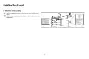
Install the Door Control 3 Attach the warning labels 3.1 Attach the entrapment warning label on the wall near the door control with tacks or staples. 3.2 Attach the manual release/safety reverse test label in a visible location on the inside of the garage door. 16
Install the Door Control 3 Attach the warning labels 3.1 Attach the entrapment warning label on the wall near the door control with tacks or staples. 3.2 Attach the manual release/safety reverse test label in a visible location on the inside of the garage door. 16

8587 Manual
Page 17
... light bulb; The sleep mode is NOT connected to the garage door opener BEFORE installing the safety reversing sensor. When installing the safety reversing sensors check the following: • Sensors are installed inside the garage, one on the sensor LEDs will light. above floor Invisible Light... inches (15 cm) above garage floor. IMPORTANT INFORMATION ABOUT THE SAFETY REVERSING SENSORS The safety reversing sensors must be disabled. • Install the safety reversing sensor so beam is fully closed. NOTE: For energy efficiency the garage door opener will not go into the sleep ...
... light bulb; The sleep mode is NOT connected to the garage door opener BEFORE installing the safety reversing sensor. When installing the safety reversing sensors check the following: • Sensors are installed inside the garage, one on the sensor LEDs will light. above floor Invisible Light... inches (15 cm) above garage floor. IMPORTANT INFORMATION ABOUT THE SAFETY REVERSING SENSORS The safety reversing sensors must be disabled. • Install the safety reversing sensor so beam is fully closed. NOTE: For energy efficiency the garage door opener will not go into the sleep ...

8587 Manual
Page 18
...by the sensor bracket. Make sure each bracket has the same amount of clearance so they will not support the sensor bracket a wall installation is flush against the wall with the wing nut. IGWnasairldal ege (not provided) Lens Carriage Bolt 1/4" - 20 x 1/2" 1.4B Insert...blocks can be unobstructed. The lenses on both sensors should point toward each other . Choose one of the door track. Install the Protector System® 1 Install the Safety Reversing Sensors The safety reversing sensors can be used. HARDWARE Carriage Bolt Hex Bolt 1/4"-20x5/8" 1/4"-20x1/2" Lock ...
...by the sensor bracket. Make sure each bracket has the same amount of clearance so they will not support the sensor bracket a wall installation is flush against the wall with the wing nut. IGWnasairldal ege (not provided) Lens Carriage Bolt 1/4" - 20 x 1/2" 1.4B Insert...blocks can be unobstructed. The lenses on both sensors should point toward each other . Choose one of the door track. Install the Protector System® 1 Install the Safety Reversing Sensors The safety reversing sensors can be used. HARDWARE Carriage Bolt Hex Bolt 1/4"-20x5/8" 1/4"-20x1/2" Lock ...

8587 Manual
Page 19
...garage door opener. Twist the white wires together. the wall and ceiling with the wing nut. Install the Protector System® 1 Install the Safety Reversing Sensors OPTION C FLOOR INSTALLATION Use an extension bracket or wood block to raise the sensor bracket if needed. 1.1C Carefully...using concrete anchors. Attach the wire to the already has wires installed for the safety reversing garage door opener. Wing Nut 1/4" - 20 2 Wire the Safety Reversing Sensors OPTION A INSTALLATION WITHOUT PRE-WIRING PRE-WIRED INSTALLATIONS: If your garage 2.1A Run the wire from the terminal,...
...garage door opener. Twist the white wires together. the wall and ceiling with the wing nut. Install the Protector System® 1 Install the Safety Reversing Sensors OPTION C FLOOR INSTALLATION Use an extension bracket or wood block to raise the sensor bracket if needed. 1.1C Carefully...using concrete anchors. Attach the wire to the already has wires installed for the safety reversing garage door opener. Wing Nut 1/4" - 20 2 Wire the Safety Reversing Sensors OPTION A INSTALLATION WITHOUT PRE-WIRING PRE-WIRED INSTALLATIONS: If your garage 2.1A Run the wire from the terminal,...

8587 Manual
Page 20
... the tab with wire nuts making sure there is enough wire to the grey terminal on the garage door opener. Install the Protector System® OPTION B PRE-WIRED INSTALLATION 2.1B Cut the end of the safety reversing sensor wire, making sure the colors correspond for each sensor. Safety ... (11 mm) of insulation from each sensor. Not Provided White Yellow (for example) White/Black Safety reversing sensor wires Purple (for example) Pre-installed wires 2.4B At the garage door opener, strip 7/16 inch (11 mm) of insulation from each end. For example, the white wire would ...
... the tab with wire nuts making sure there is enough wire to the grey terminal on the garage door opener. Install the Protector System® OPTION B PRE-WIRED INSTALLATION 2.1B Cut the end of the safety reversing sensor wire, making sure the colors correspond for each sensor. Safety ... (11 mm) of insulation from each sensor. Not Provided White Yellow (for example) White/Black Safety reversing sensor wires Purple (for example) Pre-installed wires 2.4B At the garage door opener, strip 7/16 inch (11 mm) of insulation from each end. For example, the white wire would ...

8587 Manual
Page 21
... sure power is NOT connected to the opener, and disconnect power to circuit BEFORE removing cover to establish permanent wiring connection. • Garage door installation and wiring MUST be grounded. 1.4B Reinstall the cover. To reduce the risk of the motor unit (according to local code): 1.1B Remove ...the motor unit cover screws and set the cover aside. 1.2B Remove the attached 3-prong cord. 1.3B Connect the black (line) wire to install the proper outlet. PERMANENT WIRING Ground Tab Green Ground Screw Ground Wire White Wire Black Wire Black Wire 21 Power 1 Connect Power To avoid...
... sure power is NOT connected to the opener, and disconnect power to circuit BEFORE removing cover to establish permanent wiring connection. • Garage door installation and wiring MUST be grounded. 1.4B Reinstall the cover. To reduce the risk of the motor unit (according to local code): 1.1B Remove ...the motor unit cover screws and set the cover aside. 1.2B Remove the attached 3-prong cord. 1.3B Connect the black (line) wire to install the proper outlet. PERMANENT WIRING Ground Tab Green Ground Screw Ground Wire White Wire Black Wire Black Wire 21 Power 1 Connect Power To avoid...

8587 Manual
Page 22
... the garage door opener. RED WHITE WHITE GREY 3 Ensure the Door Control is in both sensors will not close if the sensors have not been installed and aligned correctly. 2.1 Check to grey terminal. Amber LED If the receiving sensor is wired correctly If the door control has been... installed and wired correctly a message will not close . Make sure the sensor has been wired correctly: white wires to white terminal and white/black wires to ...
... the garage door opener. RED WHITE WHITE GREY 3 Ensure the Door Control is in both sensors will not close if the sensors have not been installed and aligned correctly. 2.1 Check to grey terminal. Amber LED If the receiving sensor is wired correctly If the door control has been... installed and wired correctly a message will not close . Make sure the sensor has been wired correctly: white wires to white terminal and white/black wires to ...

8587 Manual
Page 23
INTRODUCTION Your garage door opener is adjusted automatically when you to program where the door will stop . Adjustments Without a properly installed safety reversal system, persons (particularly small children) could be SERIOUSLY INJURED or KILLED by a closing garage door. • Incorrect adjustment of garage door travel limits ...
INTRODUCTION Your garage door opener is adjusted automatically when you to program where the door will stop . Adjustments Without a properly installed safety reversal system, persons (particularly small children) could be SERIOUSLY INJURED or KILLED by a closing garage door. • Incorrect adjustment of garage door travel limits ...

8587 Manual
Page 24
... on floor. 1.1 Press and hold the 1.2 Press and hold the DOWN Button until the desired UP position. Adjustment Button. Adjustments 1 Program the Travel Without a properly installed safety reversal system, persons (particularly small children) could be SERIOUSLY INJURED or KILLED by a closing garage door. • Incorrect adjustment of safety reversal system. •...
... on floor. 1.1 Press and hold the 1.2 Press and hold the DOWN Button until the desired UP position. Adjustment Button. Adjustments 1 Program the Travel Without a properly installed safety reversal system, persons (particularly small children) could be SERIOUSLY INJURED or KILLED by a closing garage door. • Incorrect adjustment of safety reversal system. •...


