8355 Manual
Page 1
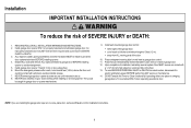
... the following information for installation instructions. PREMIUM Series Belt Drive Garage Door Opener Model 8355 - 1/2 hp FOR RESIDENTIAL USE ONLY ■ Please read this manual and the enclosed safety materials carefully! ■ Fasten the manual near the garage door after installation. ■ The door... WILL NOT CLOSE unless the Protector System® is connected and properly aligned. ■ Periodic checks of the garage door opener are required to ensure safe operation. ■ The model number label is located on a one-piece door, visit www.liftmaster...
... the following information for installation instructions. PREMIUM Series Belt Drive Garage Door Opener Model 8355 - 1/2 hp FOR RESIDENTIAL USE ONLY ■ Please read this manual and the enclosed safety materials carefully! ■ Fasten the manual near the garage door after installation. ■ The door... WILL NOT CLOSE unless the Protector System® is connected and properly aligned. ■ Periodic checks of the garage door opener are required to ensure safe operation. ■ The model number label is located on a one-piece door, visit www.liftmaster...
8355 Manual
Page 2
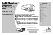
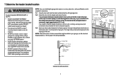
... not comply with the instructions and warnings contained in this manual. The hazard may not work properly. 5. Release the door. If balanced, it should be installed within 4 feet (1.2 m) to the left or right of damage to the garage door. 2. Raise and lower the door to avoid malfunction and damage. ... floor and the bottom of which are under EXTREME tension. • Disable ALL locks and remove ALL ropes connected to garage door BEFORE installation and operating garage door opener to avoid entanglement. 5/32 3/16 5/16 12 To prevent damage to garage door and opener: •...
... not comply with the instructions and warnings contained in this manual. The hazard may not work properly. 5. Release the door. If balanced, it should be installed within 4 feet (1.2 m) to the left or right of damage to the garage door. 2. Raise and lower the door to avoid malfunction and damage. ... floor and the bottom of which are under EXTREME tension. • Disable ALL locks and remove ALL ropes connected to garage door BEFORE installation and operating garage door opener to avoid entanglement. 5/32 3/16 5/16 12 To prevent damage to garage door and opener: •...
8355 Manual
Page 3
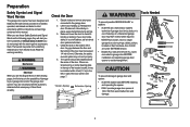
Curved door arm E. Rail I SECURITY✚ 2.0TM ACCESSORIES 882LM Multi-Function Door Control 893LM Remote Control Hardware Installation Hex Bolt 5/16"-18 x 7/8" (4) Lag Screw 5/16"-9 x 1-5/8" (2) Clevis Pin 5/16" x 2-3/4" (1) Clevis Pin 5/16" x 1-1/4" (1) Clevis Pin 5/16" x 1" (1) Nut 5/16"-18 (4) Lock Washer 5/16" (4) Self-Threading Screw 1/4"-...
Curved door arm E. Rail I SECURITY✚ 2.0TM ACCESSORIES 882LM Multi-Function Door Control 893LM Remote Control Hardware Installation Hex Bolt 5/16"-18 x 7/8" (4) Lag Screw 5/16"-9 x 1-5/8" (2) Clevis Pin 5/16" x 2-3/4" (1) Clevis Pin 5/16" x 1-1/4" (1) Clevis Pin 5/16" x 1" (1) Nut 5/16"-18 (4) Lock Washer 5/16" (4) Self-Threading Screw 1/4"-...
8355 Manual
Page 6
.... 14. To be caught in plain view on properly balanced and lubricated garage door. Installation IMPORTANT INSTALLATION INSTRUCTIONS WARNING To reduce the risk of installation, test safety reversal system. Install garage door opener ONLY on inside of children at least 6 feet (1.83 m) above floor.... Place entrapment warning label on contact with vehicles to -Close functionality if operating either one -piece door, visit www.liftmaster.com for installation instructions. 6 ALL repairs to garage door control. 11. Door MUST reverse on wall next to cables, spring assemblies ...
.... 14. To be caught in plain view on properly balanced and lubricated garage door. Installation IMPORTANT INSTALLATION INSTRUCTIONS WARNING To reduce the risk of installation, test safety reversal system. Install garage door opener ONLY on inside of children at least 6 feet (1.83 m) above floor.... Place entrapment warning label on contact with vehicles to -Close functionality if operating either one -piece door, visit www.liftmaster.com for installation instructions. 6 ALL repairs to garage door control. 11. Door MUST reverse on wall next to cables, spring assemblies ...
8355 Manual
Page 7
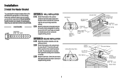
... a trained door systems technician if garage door binds, sticks, or is in your door to the highest point of travel clearance for ceiling installation. To be enabled ONLY when operating a sectional door. This height will provide travel as shown. Header Wall 2" (5 cm) Track Highest ... when required. • DO NOT enable the Timer-to-Close functionality if operating either one -piece door, visit www.liftmaster.com for installation instructions. 1.1 Close the door and mark the inside vertical centerline of balance. An unbalanced garage door might NOT reverse when required.
... a trained door systems technician if garage door binds, sticks, or is in your door to the highest point of travel clearance for ceiling installation. To be enabled ONLY when operating a sectional door. This height will provide travel as shown. Header Wall 2" (5 cm) Track Highest ... when required. • DO NOT enable the Timer-to-Close functionality if operating either one -piece door, visit www.liftmaster.com for installation instructions. 1.1 Close the door and mark the inside vertical centerline of balance. An unbalanced garage door might NOT reverse when required.
8355 Manual
Page 8
.... HARDWARE Lag Screw 5/16" - 9 x 1-5/8" OPTION A WALL INSTALLATION 2.1A Center the bracket on the vertical centerline with lag screws. If installing into masonry, use the holes designated for your particular requirements. Do not install the header bracket over drywall. Drill 3/16" pilot holes and fasten ... mark, no more than 6" (15 cm) from the wall. Follow the instructions which will work best for ceiling mount). Installation 2 Install the Header Bracket You can be mounted flush against the ceiling when clearance is pointing toward the ceiling). 2.2A Mark the vertical...
.... HARDWARE Lag Screw 5/16" - 9 x 1-5/8" OPTION A WALL INSTALLATION 2.1A Center the bracket on the vertical centerline with lag screws. If installing into masonry, use the holes designated for your particular requirements. Do not install the header bracket over drywall. Drill 3/16" pilot holes and fasten ... mark, no more than 6" (15 cm) from the wall. Follow the instructions which will work best for ceiling mount). Installation 2 Install the Header Bracket You can be mounted flush against the ceiling when clearance is pointing toward the ceiling). 2.2A Mark the vertical...
8355 Manual
Page 10
... on your garage. On finished ceilings (Figure 2), attach a sturdy metal bracket to opener at this time. Operate the door manually. Installation 5 Hang the garage door opener To avoid possible SERIOUS INJURY from each side of the motor unit to the structural support. 5.2 Cut...Drill 3/16" pilot holes in line with the header bracket if the bracket is not centered above the door). 5.7 Remove the 2x4. Two representative installations are not provided. FIGURE 1 Unfinished Ceiling FIGURE 3 Measure Distance Nut 5/16"-18 FIGURE 2 Finished Ceiling Not Provided (Not Provided) Lag Screws 5/...
... on your garage. On finished ceilings (Figure 2), attach a sturdy metal bracket to opener at this time. Operate the door manually. Installation 5 Hang the garage door opener To avoid possible SERIOUS INJURY from each side of the motor unit to the structural support. 5.2 Cut...Drill 3/16" pilot holes in line with the header bracket if the bracket is not centered above the door). 5.7 Remove the 2x4. Two representative installations are not provided. FIGURE 1 Unfinished Ceiling FIGURE 3 Measure Distance Nut 5/16"-18 FIGURE 2 Finished Ceiling Not Provided (Not Provided) Lag Screws 5/...

8355 Manual
Page 11
... fall. 7.1 Insert one end of the end panel or light socket: • Use ONLY A19 incandescent (100W maximum) or compact fluorescent (26W maximum) light bulbs. 6 Install the light bulbs 6.1 Pull on the top center of the light lens and rotate the To prevent possible OVERHEATING of the emergency release rope through...
... fall. 7.1 Insert one end of the end panel or light socket: • Use ONLY A19 incandescent (100W maximum) or compact fluorescent (26W maximum) light bulbs. 6 Install the light bulbs 6.1 Pull on the top center of the light lens and rotate the To prevent possible OVERHEATING of the emergency release rope through...
8355 Manual
Page 12
...Centerline of angle iron as follows, depending on wood doors. FIGURE 1 Fiberglass, aluminum or lightweight steel garage doors WILL REQUIRE reinforcement BEFORE installation of Garage Door 12 The best solution is needed for direct attachment of the clevis pin and door arm. A vertical reinforcement brace ...should be long enough to be secured to check with your garage door manufacturer for an opener installation door reinforcement kit. In this case you will not need the door bracket; Secure the door bracket using a vertical angle iron...
...Centerline of angle iron as follows, depending on wood doors. FIGURE 1 Fiberglass, aluminum or lightweight steel garage doors WILL REQUIRE reinforcement BEFORE installation of Garage Door 12 The best solution is needed for direct attachment of the clevis pin and door arm. A vertical reinforcement brace ...should be long enough to be secured to check with your garage door manufacturer for an opener installation door reinforcement kit. In this case you will not need the door bracket; Secure the door bracket using a vertical angle iron...
8355 Manual
Page 14
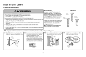
... the door the illustrations. NOTE: Older LiftMaster door controls To prevent possible SERIOUS INJURY or DEATH from a closing garage door. closing garage door: and third party products are no obstructions to either screw. 7/16" (11 mm) PRE-WIRED INSTALLATIONS: Choose Wall any other Security+ 2.0™...of 5 feet (1.5 m), and away from electrocution: • Be sure power is properly adjusted, and there are not compatible. • Install door control within sight of the door at • NEVER permit children to operate or play with door control push buttons or remote control ...
... the door the illustrations. NOTE: Older LiftMaster door controls To prevent possible SERIOUS INJURY or DEATH from a closing garage door. closing garage door: and third party products are no obstructions to either screw. 7/16" (11 mm) PRE-WIRED INSTALLATIONS: Choose Wall any other Security+ 2.0™...of 5 feet (1.5 m), and away from electrocution: • Be sure power is properly adjusted, and there are not compatible. • Install door control within sight of the door at • NEVER permit children to operate or play with door control push buttons or remote control ...
8355 Manual
Page 15
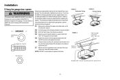
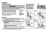
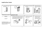
...wall and drill a 5/32 inch (4 mm) hole for gang box or pre-wired installations). Attach the wire to the red and white terminals on the garage door opener. RED WHITE WHITE GREY PRE-...WIRED INSTALLATIONS: When wiring the door control to the garage door opener make sure you use the...the top screw. 1.8 Position the bottom hole of the door control over the screw and slide down into place. Install the Door Control k 1.5 Position the bottom hole of the door control over the screw and slide down into place...
...wall and drill a 5/32 inch (4 mm) hole for gang box or pre-wired installations). Attach the wire to the red and white terminals on the garage door opener. RED WHITE WHITE GREY PRE-...WIRED INSTALLATIONS: When wiring the door control to the garage door opener make sure you use the...the top screw. 1.8 Position the bottom hole of the door control over the screw and slide down into place. Install the Door Control k 1.5 Position the bottom hole of the door control over the screw and slide down into place...
8355 Manual
Page 16
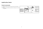
Install the Door Control 3 Attach the warning labels 3.1 Attach the entrapment warning label on the wall near the door control with tacks or staples. 3.2 Attach the manual release/safety reverse test label in a visible location on the inside of the garage door. 16
Install the Door Control 3 Attach the warning labels 3.1 Attach the entrapment warning label on the wall near the door control with tacks or staples. 3.2 Attach the manual release/safety reverse test label in a visible location on the inside of the garage door. 16
8355 Manual
Page 17
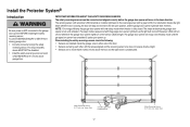
... sensor LEDs will flash 10 times. IMPORTANT INFORMATION ABOUT THE SAFETY REVERSING SENSORS The safety reversing sensors must be disabled. • Install the safety reversing sensor so beam is unobstructed. To prevent SERIOUS INJURY or DEATH from closing , the door will stop and reverse...will light. If an obstruction breaks the light beam while the door is NOT connected to the garage door opener BEFORE installing the safety reversing sensor. Install the Protector System® Introduction Be sure power is closing garage door: • Correctly connect and align the safety ...
... sensor LEDs will flash 10 times. IMPORTANT INFORMATION ABOUT THE SAFETY REVERSING SENSORS The safety reversing sensors must be disabled. • Install the safety reversing sensor so beam is unobstructed. To prevent SERIOUS INJURY or DEATH from closing , the door will stop and reverse...will light. If an obstruction breaks the light beam while the door is NOT connected to the garage door opener BEFORE installing the safety reversing sensor. Install the Protector System® Introduction Be sure power is closing garage door: • Correctly connect and align the safety ...
8355 Manual
Page 18
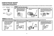
... Carriage Bolt 1/4"-20x1/2" OPTION A DOOR TRACK INSTALLATION 1.1A Slide the curved arms of the sensor bracket around the edge of the following installations. Wing Nut 1/4"-20 Wing Nut 1/4" - 20 Carriage Bolt 1/4" - 20 x 1/2" OPTION B WALL INSTALLATION If additional clearance is needed an extension bracket ... same amount of clearance so they will not support the sensor bracket a wall installation is flush against the wall with the wing nut. Install the Protector System® 1 Install the Safety Reversing Sensors The safety reversing sensors can be unobstructed. If the door...
... Carriage Bolt 1/4"-20x1/2" OPTION A DOOR TRACK INSTALLATION 1.1A Slide the curved arms of the sensor bracket around the edge of the following installations. Wing Nut 1/4"-20 Wing Nut 1/4" - 20 Carriage Bolt 1/4" - 20 x 1/2" OPTION B WALL INSTALLATION If additional clearance is needed an extension bracket ... same amount of clearance so they will not support the sensor bracket a wall installation is flush against the wall with the wing nut. Install the Protector System® 1 Install the Safety Reversing Sensors The safety reversing sensors can be unobstructed. If the door...

8355 Manual
Page 19
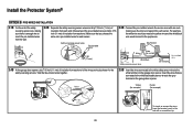
...to sensors, see page 20. RED WHITE WHITE GREY Insulated Staple (Not shown) 7/16" (11 mm) 19 Install the Protector System® 1 Install the Safety Reversing Sensors OPTION C FLOOR INSTALLATION Use an extension bracket (not provided) or wood block to raise the sensor bracket if needed. 1.1C Carefully ... with a screwdriver tip. Make sure the lens is not obstructed by the sensor bracket. Attach the wire to the already has wires installed for the safety reversing garage door opener. Twist the white/black wires together. 2.3A Insert the white wires into the grey terminal on...
...to sensors, see page 20. RED WHITE WHITE GREY Insulated Staple (Not shown) 7/16" (11 mm) 19 Install the Protector System® 1 Install the Safety Reversing Sensors OPTION C FLOOR INSTALLATION Use an extension bracket (not provided) or wood block to raise the sensor bracket if needed. 1.1C Carefully ... with a screwdriver tip. Make sure the lens is not obstructed by the sensor bracket. Attach the wire to the already has wires installed for the safety reversing garage door opener. Twist the white/black wires together. 2.3A Insert the white wires into the grey terminal on...
8355 Manual
Page 20
...to the white terminal on the garage door opener. Not Provided White Yellow (for example) White/Black Safety reversing sensor wires Purple (for example) Pre-installed wires 2.4B At the garage door opener, strip 7/16 inch (11 mm) of insulation from the terminal, push in the tab with wire nuts... safety reversing sensor wires and strip 7/16 inch (11 mm) of insulation from each end. Insert the wires that you choose the same color pre-installed wires for each end. Yellow Purple Yellow (for example) Purple (for example) RED WHITE WHITE GREY 7/16" (11 mm) To insert or remove ...
...to the white terminal on the garage door opener. Not Provided White Yellow (for example) White/Black Safety reversing sensor wires Purple (for example) Pre-installed wires 2.4B At the garage door opener, strip 7/16 inch (11 mm) of insulation from the terminal, push in the tab with wire nuts... safety reversing sensor wires and strip 7/16 inch (11 mm) of insulation from each end. Insert the wires that you choose the same color pre-installed wires for each end. Yellow Purple Yellow (for example) Purple (for example) RED WHITE WHITE GREY 7/16" (11 mm) To insert or remove ...
8355 Manual
Page 21
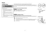
...TYPICAL WIRING 1.1A Plug in the top of electric shock, your local code, refer to establish permanent wiring connection. • Garage door installation and wiring MUST be grounded. 1.4B Reinstall the cover. TYPICAL WIRING PERMANENT WIRING Ground Tab Green Ground Screw Ground Wire White Wire Black ...outlet. Be sure the opener is grounded. The opener must be in compliance with a third grounding pin. Power 1 Connect Power To avoid installation difficulties, do not activate the garage door opener at this time. To reduce the risk of the motor unit (according to local code):...
...TYPICAL WIRING 1.1A Plug in the top of electric shock, your local code, refer to establish permanent wiring connection. • Garage door installation and wiring MUST be grounded. 1.4B Reinstall the cover. TYPICAL WIRING PERMANENT WIRING Ground Tab Green Ground Screw Ground Wire White Wire Black ...outlet. Be sure the opener is grounded. The opener must be in compliance with a third grounding pin. Power 1 Connect Power To avoid installation difficulties, do not activate the garage door opener at this time. To reduce the risk of the motor unit (according to local code):...
8355 Manual
Page 22
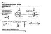
... wired correctly, the command LED behind the push bar will not close if the sensors have not been installed and aligned correctly. 2.1 Check to make sure the LEDs in both sensors will flash ten times. IF THE GREEN LED ON THE RECEIVING SENSOR IS ...
... wired correctly, the command LED behind the push bar will not close if the sensors have not been installed and aligned correctly. 2.1 Check to make sure the LEDs in both sensors will flash ten times. IF THE GREEN LED ON THE RECEIVING SENSOR IS ...
8355 Manual
Page 23
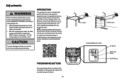
... new garage door opener use your smartphone to read the QR Code below: To prevent damage to make setup and adjustments easy. Adjustments Without a properly installed safety reversal system, persons (particularly small children) could be SERIOUSLY INJURED or KILLED by a closing garage door. • Incorrect adjustment of garage door travel limits...
... new garage door opener use your smartphone to read the QR Code below: To prevent damage to make setup and adjustments easy. Adjustments Without a properly installed safety reversal system, persons (particularly small children) could be SERIOUSLY INJURED or KILLED by a closing garage door. • Incorrect adjustment of garage door travel limits...

8355 Manual
Page 24
... UP position. NOTE: The UP and DOWN Buttons can be used to flash. If you are unable to flash. Adjustments 1 Program the Travel Without a properly installed safety reversal system, persons (particularly small children) could be SERIOUSLY INJURED or KILLED by a closing garage door. • Incorrect adjustment of safety reversal system. •...
... UP position. NOTE: The UP and DOWN Buttons can be used to flash. If you are unable to flash. Adjustments 1 Program the Travel Without a properly installed safety reversal system, persons (particularly small children) could be SERIOUSLY INJURED or KILLED by a closing garage door. • Incorrect adjustment of safety reversal system. •...


