
3800 Manual
Page 1
® GARAGE DOOR OPENER Model 3800 For Residential Sectional Doors With Torsion Assemblies Only Com Details The Chamberlain Group, Inc. 845 Larch Avenue Elmhurst, Illinois 60126-1196 www.liftmaster.com patible with See Page 13 for Owner's Manual ■ Please read this manual and the enclosed safety... materials carefully! ■ Fasten the manual near the garage door after installation. ■ The door WILL NOT CLOSE unless...
® GARAGE DOOR OPENER Model 3800 For Residential Sectional Doors With Torsion Assemblies Only Com Details The Chamberlain Group, Inc. 845 Larch Avenue Elmhurst, Illinois 60126-1196 www.liftmaster.com patible with See Page 13 for Owner's Manual ■ Please read this manual and the enclosed safety... materials carefully! ■ Fasten the manual near the garage door after installation. ■ The door WILL NOT CLOSE unless...
3800 Manual
Page 2
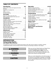
...or change a keyless entry PIN 27 Programming work light or additional work light . . . . . .28 Repair Parts 29-30 Installation parts 29 Motor unit assembly parts 30 Accessories 31 Repair Parts and Service 32 Warranty 32 INTRODUCTION Safety Symbol Review and Signal Word Review This...death if you do not comply with the instructions and warnings contained in strict accordance with the warnings that accompany it is installed, operated, maintained and tested in this manual. Read them . WARNING Mechanical WCAAURTNIIONNG WAElRecNtriIcNalG WARNING CAUTION WARNING When you see this...
...or change a keyless entry PIN 27 Programming work light or additional work light . . . . . .28 Repair Parts 29-30 Installation parts 29 Motor unit assembly parts 30 Accessories 31 Repair Parts and Service 32 Warranty 32 INTRODUCTION Safety Symbol Review and Signal Word Review This...death if you do not comply with the instructions and warnings contained in strict accordance with the warnings that accompany it is installed, operated, maintained and tested in this manual. Read them . WARNING Mechanical WCAAURTNIIONNG WAElRecNtriIcNalG WARNING CAUTION WARNING When you see this...

3800 Manual
Page 3
... Doors up and down or left or right side of door. ft. • 1" (2.5 cm) torsion bar only. • Review or inspect proposed installation area. Must have minimum of 8" (20.3 cm) between the side garage wall (or obstruction) and the end of torsion bar. • The torsion...; A model 475LM EverChargeTM Battery Backup System is strongly recommended if there is raised and lowered. This opener is required within 6' (1.8 m) of the installation area. Must have minimum of 3" (7.6 cm) between floor Sensor and bottom of door must not exceed 1/4" (6 mm). Motor unit Cable Tension Monitor...
... Doors up and down or left or right side of door. ft. • 1" (2.5 cm) torsion bar only. • Review or inspect proposed installation area. Must have minimum of 8" (20.3 cm) between the side garage wall (or obstruction) and the end of torsion bar. • The torsion...; A model 475LM EverChargeTM Battery Backup System is strongly recommended if there is raised and lowered. This opener is required within 6' (1.8 m) of the installation area. Must have minimum of 3" (7.6 cm) between floor Sensor and bottom of door must not exceed 1/4" (6 mm). Motor unit Cable Tension Monitor...
3800 Manual
Page 4
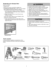
...the entire travel of which are under EXTREME tension. • Disable ALL locks and remove ALL ropes connected to garage door BEFORE installing and operating garage door WARNING opener to avoid malfunction and damage. Verify equal cable tension on each side of the opener, instructions ... a trained door systems technician if garage door binds, sticks or is not sticking or binding: 1. Sectional Door Tools needed During assembly, installation and adjustment of door. Lift the door about halfway as illustrated below. WARNING To prevent possible SERIOUS INJURY or DEATH: CAUTION • ...
...the entire travel of which are under EXTREME tension. • Disable ALL locks and remove ALL ropes connected to garage door BEFORE installing and operating garage door WARNING opener to avoid malfunction and damage. Verify equal cable tension on each side of the opener, instructions ... a trained door systems technician if garage door binds, sticks or is not sticking or binding: 1. Sectional Door Tools needed During assembly, installation and adjustment of door. Lift the door about halfway as illustrated below. WARNING To prevent possible SERIOUS INJURY or DEATH: CAUTION • ...
3800 Manual
Page 5
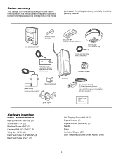
... Protector System® (2) Safety Reversing Sensors (1 Sending Eye and 1 Receiving Eye) with 2-Conductor White & White/Black Bell Wire attached Safety Labels and Literature Hardware Inventory INSTALLATION HARDWARE Hex Screw #14-10x1-7/8" (4) Screw #6x-1-1/4" (2) Machine Screw #6x1" (2) Carriage Bolt 1/4"-20x1/2" (2) Wing Nut 1/4"-20 (2) Pan Head Screw 1/4"-20x1/2" (2) Hex Head Screw #8x1" (2) Self...
... Protector System® (2) Safety Reversing Sensors (1 Sending Eye and 1 Receiving Eye) with 2-Conductor White & White/Black Bell Wire attached Safety Labels and Literature Hardware Inventory INSTALLATION HARDWARE Hex Screw #14-10x1-7/8" (4) Screw #6x-1-1/4" (2) Machine Screw #6x1" (2) Carriage Bolt 1/4"-20x1/2" (2) Wing Nut 1/4"-20 (2) Pan Head Screw 1/4"-20x1/2" (2) Hex Head Screw #8x1" (2) Self...
3800 Manual
Page 6
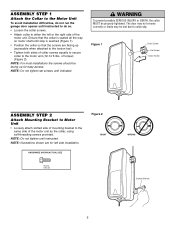
NOTE: For most installations the screws should be facing up (accessible when attached to the torsion bar). • Tighten both sides of collar screws equally to secure collar to ... screws provided. The door may not reverse correctly or limits may be properly tightened. ASSEMBLY STEP 1 Attach the Collar to the Motor Unit To avoid installation difficulties, do not run the garage door opener until instructed to do so. • Loosen the collar screws. • Attach collar to either the left...
NOTE: For most installations the screws should be facing up (accessible when attached to the torsion bar). • Tighten both sides of collar screws equally to secure collar to ... screws provided. The door may not reverse correctly or limits may be properly tightened. ASSEMBLY STEP 1 Attach the Collar to the Motor Unit To avoid installation difficulties, do not run the garage door opener until instructed to do so. • Loosen the collar screws. • Attach collar to either the left...
3800 Manual
Page 7
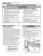
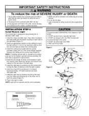
... 5 Mount emergency release handle no higher than 6 feet (1.83 m) above floor. 6. Drill through steel plate if needed. 4. of operator. Install garage door opener ONLY on wall next to prevent antenna from being entangled in SEVERE INJURY or DEATH. 3. Mark the bracket holes. Securely tighten ...be made by sliding the collar over the end of 5 feet (1.5 m). • away from torsion bar and remove the opener. WARNING INSTALLATION IMPORTANT INSTALLATION INSTRUCTIONS WARNING To reduce the risk of the door. 9. Use a staple to secure the antenna wire to garage door control. 10. ...
... 5 Mount emergency release handle no higher than 6 feet (1.83 m) above floor. 6. Drill through steel plate if needed. 4. of operator. Install garage door opener ONLY on wall next to prevent antenna from being entangled in SEVERE INJURY or DEATH. 3. Mark the bracket holes. Securely tighten ...be made by sliding the collar over the end of 5 feet (1.5 m). • away from torsion bar and remove the opener. WARNING INSTALLATION IMPORTANT INSTALLATION INSTRUCTIONS WARNING To reduce the risk of the door. 9. Use a staple to secure the antenna wire to garage door control. 10. ...
3800 Manual
Page 8
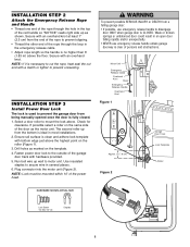
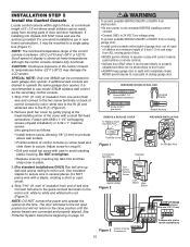
... in the top of the red handle so "NOTICE" reads right side up as shown. Plug connector into the motor unit (Figure 2). INSTALLATION STEP 3 Install Power Door Lock The lock is used to prevent the garage door from the bottom is CLOSED. Use insulated staples to prevent unraveling. NOTE:...Lock Screw 1/4-20 x 1/2" (2) Staples 8 Ensure rail surface is clean and adhere lock template with an overhand knot. Drill holes as the motor unit. INSTALLATION STEP 2 Attach the Emergency Release Rope and Handle • Thread one end of the rope through the loop in the emergency release cable. • ...
... in the top of the red handle so "NOTICE" reads right side up as shown. Plug connector into the motor unit (Figure 2). INSTALLATION STEP 3 Install Power Door Lock The lock is used to prevent the garage door from the bottom is CLOSED. Use insulated staples to prevent unraveling. NOTE:...Lock Screw 1/4-20 x 1/2" (2) Staples 8 Ensure rail surface is clean and adhere lock template with an overhand knot. Drill holes as the motor unit. INSTALLATION STEP 2 Attach the Emergency Release Rope and Handle • Thread one end of the rope through the loop in the emergency release cable. • ...
3800 Manual
Page 9
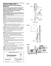
...sure cable tension monitor is shipped for anchors). 4. Mark and drill 3/16" pilot holes for screws (pilot holes are not required for left side installation. Make sure there is no obstructions in the down direction. HARDWARE SHOWN ACTUAL SIZE Figure 1 Opener Torsion Bar Drum Cable 2"-6" (5 cm15 cm) Cable... mounted on opposite side of door. NOTE: The cable tension monitor is located over a wood support member. The cable tension monitor must be installed on top of the door as a device to the wall using the wall anchors (2) and the #8 hex head screws (2) provided in cable...
...sure cable tension monitor is shipped for anchors). 4. Mark and drill 3/16" pilot holes for screws (pilot holes are not required for left side installation. Make sure there is no obstructions in the down direction. HARDWARE SHOWN ACTUAL SIZE Figure 1 Opener Torsion Bar Drum Cable 2"-6" (5 cm15 cm) Cable... mounted on opposite side of door. NOTE: The cable tension monitor is located over a wood support member. The cable tension monitor must be installed on top of the door as a device to the wall using the wall anchors (2) and the #8 hex head screws (2) provided in cable...
3800 Manual
Page 10
... Connections WHT To release wire, push in new home construction), it is properly adjusted and there are connected and properly aligned. If installing into gang box) as the secondary control console. 1. If additional wall controls are desired to operate the same garage door opener, ... of control console on back of control console by inserting top tabs first and then snap cover in several places. WARNING WARNING INSTALCLATUITOINOSNTEP 5 Install the Control Console Locate control console within sight of garage door, out of reach of children at a minimum height of 5 feet (1.5 ...
... Connections WHT To release wire, push in new home construction), it is properly adjusted and there are connected and properly aligned. If installing into gang box) as the secondary control console. 1. If additional wall controls are desired to operate the same garage door opener, ... of control console on back of control console by inserting top tabs first and then snap cover in several places. WARNING WARNING INSTALCLATUITOINOSNTEP 5 Install the Control Console Locate control console within sight of garage door, out of reach of children at a minimum height of 5 feet (1.5 ...
3800 Manual
Page 11
...; DO NOT use wall anchors provided. This portable luminaire has a polarized plug (one blade is designed to latch into a standard 120V outlet. 1. Install the ceiling mount plate with an extension cord unless plug can not be fully inserted. 6. Determine the length of an electrical outlet so that the... are away from moving parts. 3. If the plug does not fit fully in the light to lock the light in place. 6. WARNING INSTALLATION STEP 6 Install Remote Light The remote light is wider than 100W. • ONLY use halogen bulbs. No pilot hole is required for ceiling mount and ...
...; DO NOT use wall anchors provided. This portable luminaire has a polarized plug (one blade is designed to latch into a standard 120V outlet. 1. Install the ceiling mount plate with an extension cord unless plug can not be fully inserted. 6. Determine the length of an electrical outlet so that the... are away from moving parts. 3. If the plug does not fit fully in the light to lock the light in place. 6. WARNING INSTALLATION STEP 6 Install Remote Light The remote light is wider than 100W. • ONLY use halogen bulbs. No pilot hole is required for ceiling mount and ...
3800 Manual
Page 12
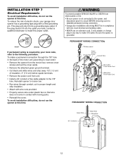
...not connected to the opener, and disconnect power to circuit BEFORE removing cover to establish permanent wiring connection. • Garage door installation and wiring MUST be in compliance with a third grounding pin. RIGHT WRONG If permanent wiring is required by your garage door ...From Power Cord PERMANENT WIRING CONNECTION Green Wire Black Wire White Wire 90˚ Connector 12 INSTAWLLAARTINOINNGSTEP 7 Electrical Requirements CAUTION To avoid installation difficulties, do not run the opener at this time. This plug will only fit into the outlet you have, contact a ...
...not connected to the opener, and disconnect power to circuit BEFORE removing cover to establish permanent wiring connection. • Garage door installation and wiring MUST be in compliance with a third grounding pin. RIGHT WRONG If permanent wiring is required by your garage door ...From Power Cord PERMANENT WIRING CONNECTION Green Wire Black Wire White Wire 90˚ Connector 12 INSTAWLLAARTINOINNGSTEP 7 Electrical Requirements CAUTION To avoid installation difficulties, do not run the opener at this time. This plug will only fit into the outlet you have, contact a ...
3800 Manual
Page 13
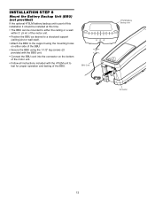
... 8 Mount the Battery Backup Unit (BBU) (not provided) If the optional 475LM battery backup unit is part of this installation it should be installed at this time. • The BBU can be mounted to either the ceiling or a wall within 3' (.9 m) of the motor unit. • Position the BBU as ...
... 8 Mount the Battery Backup Unit (BBU) (not provided) If the optional 475LM battery backup unit is part of this installation it should be installed at this time. • The BBU can be mounted to either the ceiling or a wall within 3' (.9 m) of the motor unit. • Position the BBU as ...
3800 Manual
Page 14
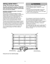
...full open position, and the opener lights will flash 10 times. above garage floor. The mounting brackets are available if needed. If installing in masonry construction, add a piece of wood at each other hardware) may interrupt the beam while the door is closing. The invisible... beam is a required safety device and cannot be disabled. above the floor. The sending eye (with a green indicator light). INSTALLATION STEP 9 Install The Protector System® The safety reversing sensor must be connected and aligned correctly before the garage door opener will detect an obstacle...
...full open position, and the opener lights will flash 10 times. above garage floor. The mounting brackets are available if needed. If installing in masonry construction, add a piece of wood at each other hardware) may interrupt the beam while the door is closing. The invisible... beam is a required safety device and cannot be disabled. above the floor. The sending eye (with a green indicator light). INSTALLATION STEP 9 Install The Protector System® The safety reversing sensor must be connected and aligned correctly before the garage door opener will detect an obstacle...
3800 Manual
Page 15
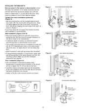
... Attach with the lip hugging the back edge of the track, as follows. If your door track will not support the bracket securely, wall installation is disconnected. They may be no higher than 6" (15 cm) above the floor. • Carefully measure and place right and left assemblies...anchors as a template to locate and drill (2) 3/16" diameter pilot holes on the wall at the same distance out from the mounting surface. Floor installation (Figure 4): • Use wood blocks or extension brackets (See Accessories) to elevate sensor brackets so the lenses will face each door track, with...
... Attach with the lip hugging the back edge of the track, as follows. If your door track will not support the bracket securely, wall installation is disconnected. They may be no higher than 6" (15 cm) above the floor. • Carefully measure and place right and left assemblies...anchors as a template to locate and drill (2) 3/16" diameter pilot holes on the wall at the same distance out from the mounting surface. Floor installation (Figure 4): • Use wood blocks or extension brackets (See Accessories) to elevate sensor brackets so the lenses will face each door track, with...

3800 Manual
Page 16
... Invisible Light Beam Protection Area 16 If the green indicator light in the opener. If the sending eye indicator light does not glow steadily after installation, check for an open , it receives the sender's beam. If the door is required. • Loosen the sending eye wing nut and...misaligned while the door is dim, realign either sensor. The sending eye amber indicator light will glow steadily if wiring connections and alignment are not installed, 10 clicks can occur at staples, or at the receiving eye. Use wing nuts to fasten safety reversing sensors to wall and ceiling. ...
... Invisible Light Beam Protection Area 16 If the green indicator light in the opener. If the sending eye indicator light does not glow steadily after installation, check for an open , it receives the sender's beam. If the door is required. • Loosen the sending eye wing nut and...misaligned while the door is dim, realign either sensor. The sending eye amber indicator light will glow steadily if wiring connections and alignment are not installed, 10 clicks can occur at staples, or at the receiving eye. Use wing nuts to fasten safety reversing sensors to wall and ceiling. ...
3800 Manual
Page 17
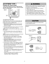
... and hold the black button until the door reaches the desired DOWN (closed , if there appears to Adjustment Steps 2, Setting the Force. WARNING Without a properly installed safety reversal system, persons CAUTION (particularly small children) could be SERIOUSLY INJURED or KILLED by using the black and purple buttons to vehicles, be sure...
... and hold the black button until the door reaches the desired DOWN (closed , if there appears to Adjustment Steps 2, Setting the Force. WARNING Without a properly installed safety reversal system, persons CAUTION (particularly small children) could be SERIOUSLY INJURED or KILLED by using the black and purple buttons to vehicles, be sure...
3800 Manual
Page 18
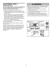
... door will travel to enter unit into Force Adjustment Mode BLACK PURPLE Figure 3 or LOCK LIGHT 18 See page 4, "Preparing your door. WARNING Without a properly installed safety reversal system, persons CAUTION (particularly small children) could be SERIOUSLY INJURED or KILLED by a closing garage door. • NEVER learn forces or limits when...
... door will travel to enter unit into Force Adjustment Mode BLACK PURPLE Figure 3 or LOCK LIGHT 18 See page 4, "Preparing your door. WARNING Without a properly installed safety reversal system, persons CAUTION (particularly small children) could be SERIOUSLY INJURED or KILLED by a closing garage door. • NEVER learn forces or limits when...
3800 Manual
Page 19
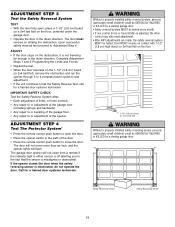
...(3.8 cm) high object (or 2x4 laid flat) on the floor. 1-1/2" (3.8 cm) board (or a 2x4 laid flat) WARNING Without a properly installed safety reversing sensor, persons CAUTION (particularly small children) could be tested. ADJUSTMENT STEP 3 Test the Safety Reversal System TEST • With the door...adjustment of the garage door (including springs and hardware). • Any repair to or buckling of the opener. WARNING Without a properly installed safety reversal system, persons CAUTION (particularly small children) could be SERIOUSLY INJURED or KILLED by a closing garage door. • Safety...
...(3.8 cm) high object (or 2x4 laid flat) on the floor. 1-1/2" (3.8 cm) board (or a 2x4 laid flat) WARNING Without a properly installed safety reversing sensor, persons CAUTION (particularly small children) could be tested. ADJUSTMENT STEP 3 Test the Safety Reversal System TEST • With the door...adjustment of the garage door (including springs and hardware). • Any repair to or buckling of the opener. WARNING Without a properly installed safety reversal system, persons CAUTION (particularly small children) could be SERIOUSLY INJURED or KILLED by a closing garage door. • Safety...
3800 Manual
Page 21
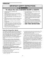
...door falling rapidly and/or unexpectedly. 7. ALWAYS disconnect electric power to operate or play with the safety reversing sensor and cable tension monitor correctly installed and aligned): 1. When the opener is complete. If closed . If the door has been stopped in an open . 2. If obstructed while... will operate with 1-1/2" (3.8 cm) high object (or a 2x4 laid flat) on the floor. 10. Using Your Garage Door Opener Your LiftMaster Security✚® opener and hand-held remote control have been factory programmed to move. • The wall-mounted Control Console: Hold the push...
...door falling rapidly and/or unexpectedly. 7. ALWAYS disconnect electric power to operate or play with the safety reversing sensor and cable tension monitor correctly installed and aligned): 1. When the opener is complete. If closed . If the door has been stopped in an open . 2. If obstructed while... will operate with 1-1/2" (3.8 cm) high object (or a 2x4 laid flat) on the floor. 10. Using Your Garage Door Opener Your LiftMaster Security✚® opener and hand-held remote control have been factory programmed to move. • The wall-mounted Control Console: Hold the push...


