
3280 Manual
Page 1
® GARAGE DOOR OPENER Model 3280 1/2HP 3280-267 1/2HP For Residential Use Only The Chamberlain Group, Inc. 845 Larch Avenue Elmhurst, Illinois 60126-1196 www.liftmaster.com Owner's Manual ■ Please read this manual and the enclosed safety materials carefully! ■ Fasten the manual near the garage door after installation. ■ The door WILL NOT CLOSE unless the Protector System® is connected and properly aligned. ■ Periodic checks of the opener are required to ensure safe operation. ■ The model number label is located on the front panel of your opener.
® GARAGE DOOR OPENER Model 3280 1/2HP 3280-267 1/2HP For Residential Use Only The Chamberlain Group, Inc. 845 Larch Avenue Elmhurst, Illinois 60126-1196 www.liftmaster.com Owner's Manual ■ Please read this manual and the enclosed safety materials carefully! ■ Fasten the manual near the garage door after installation. ■ The door WILL NOT CLOSE unless the Protector System® is connected and properly aligned. ■ Periodic checks of the opener are required to ensure safe operation. ■ The model number label is located on the front panel of your opener.
3280 Manual
Page 2
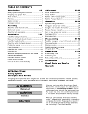
...When you see these Safety Symbols and Signal Words on the following pages, they will alert you to the possibility of damage to your garage door opener 28 Having a problem 29 Diagnostic chart 30 Programming 31-32 To add or reprogram a hand-held remote control .....31 To erase all... 33 Motor unit assembly parts 34 Accessories 35 Repair Parts and Service 36 Warranty 36 INTRODUCTION Safety Symbol and Signal Word Review This garage door opener has been designed and tested to offer safe service provided it is installed, operated, maintained and tested in this Signal Word on ...
...When you see these Safety Symbols and Signal Words on the following pages, they will alert you to the possibility of damage to your garage door opener 28 Having a problem 29 Diagnostic chart 30 Programming 31-32 To add or reprogram a hand-held remote control .....31 To erase all... 33 Motor unit assembly parts 34 Accessories 35 Repair Parts and Service 36 Warranty 36 INTRODUCTION Safety Symbol and Signal Word Review This garage door opener has been designed and tested to offer safe service provided it is installed, operated, maintained and tested in this Signal Word on ...
3280 Manual
Page 3
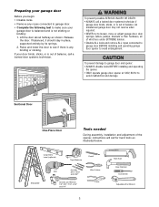
...is not sticking or binding: 1. To prevent damage to garage door and opener: • ALWAYS disable locks BEFORE installing and operating the opener. • ONLY operate garage door opener at 120V, 60 Hz to avoid entanglement. If your garage door is balanced and is out of which are under... EXTREME tension. • Disable ALL locks and remove ALL ropes connected to garage door BEFORE installing and operating garage door opener to avoid malfunction and damage. Carpenter's Level (optional) 12 Tape Measure Pencil Stepladder Drill Bits Drill 3/16", ...
...is not sticking or binding: 1. To prevent damage to garage door and opener: • ALWAYS disable locks BEFORE installing and operating the opener. • ONLY operate garage door opener at 120V, 60 Hz to avoid entanglement. If your garage door is balanced and is out of which are under... EXTREME tension. • Disable ALL locks and remove ALL ropes connected to garage door BEFORE installing and operating garage door opener to avoid malfunction and damage. Carpenter's Level (optional) 12 Tape Measure Pencil Stepladder Drill Bits Drill 3/16", ...
3280 Manual
Page 4
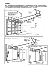
... Safety must not exceed 1/4" (6 mm) Reversing Sensor 4 Safety Reversing Sensor Safety Gap between floor and bottom of your opener. SECTIONAL DOOR INSTALLATION Horizontal and vertical reinforcement is required. See page 19 for lightweight garage doors (fiberglass, steel, aluminum, door with the installation of door must not exceed 1/4" (6 mm). Header Wall FINISHED CEILING...
... Safety must not exceed 1/4" (6 mm) Reversing Sensor 4 Safety Reversing Sensor Safety Gap between floor and bottom of your opener. SECTIONAL DOOR INSTALLATION Horizontal and vertical reinforcement is required. See page 19 for lightweight garage doors (fiberglass, steel, aluminum, door with the installation of door must not exceed 1/4" (6 mm). Header Wall FINISHED CEILING...
3280 Manual
Page 5
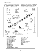
Carton Inventory Your garage door opener is packaged in the foam. Parts may be stuck in two cartons ... packing material. LOCK LIGHT Multi-Function Door Control Panel SECURITY✚® 3-Button Remote Control Models 3280 (1) 3280-267 (2) Remote Control Transmitter Visor Clip Styrofoam Belt Cap Retainer Belt Motor Unit with 2 Light Lenses SECURITY✚®...; Keyless Entry Model 3280-267 ONLY One-Piece Rail CEILING MOUNT ONLY UP Door Bracket Belt Pulley Bracket Trolley 2-Conductor Bell Wire...
Carton Inventory Your garage door opener is packaged in the foam. Parts may be stuck in two cartons ... packing material. LOCK LIGHT Multi-Function Door Control Panel SECURITY✚® 3-Button Remote Control Models 3280 (1) 3280-267 (2) Remote Control Transmitter Visor Clip Styrofoam Belt Cap Retainer Belt Motor Unit with 2 Light Lenses SECURITY✚®...; Keyless Entry Model 3280-267 ONLY One-Piece Rail CEILING MOUNT ONLY UP Door Bracket Belt Pulley Bracket Trolley 2-Conductor Bell Wire...

3280 Manual
Page 6
... bolts/fasteners mounted in top of motor unit. • Align rail and styrofoam over the motor unit sprocket. Rotate about 1/4 turn until instructed to door opener. • Position belt over sprocket. USE ONLY THIS TYPE AND SIZE BOLT Washered Bolt 5/16"-18x1/2" Rail Hole Sprocket Rail Hole ASSEMBLY STEP 2 Set the... Use only 3t/h5/e92s-e5/b16o/9lt2s-!5/U21s/9e2 -o6f/2a/9n2y other bolts will cause6/1s1e/9r2ious damage to do not run the garage door opener until the spring releases and snaps the nut ring against the trolley (Figure 2). • Place a 7/16...
... bolts/fasteners mounted in top of motor unit. • Align rail and styrofoam over the motor unit sprocket. Rotate about 1/4 turn until instructed to door opener. • Position belt over sprocket. USE ONLY THIS TYPE AND SIZE BOLT Washered Bolt 5/16"-18x1/2" Rail Hole Sprocket Rail Hole ASSEMBLY STEP 2 Set the... Use only 3t/h5/e92s-e5/b16o/9lt2s-!5/U21s/9e2 -o6f/2a/9n2y other bolts will cause6/1s1e/9r2ious damage to do not run the garage door opener until the spring releases and snaps the nut ring against the trolley (Figure 2). • Place a 7/16...
3280 Manual
Page 7
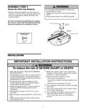
... floor. 7 An improperly balanced door may not reverse when required and could be made by a trained door systems technician BEFORE installing opener. 4. Install garage door opener 7 feet (2.13 m) or more above floor. 7. Upon completion of SEVERE INJURY or DEATH: 1. Please read the following warnings ... INSTRUCTIONS WARNING To reduce the risk of installation, test safety reversal system. Attach with the two holes in mounting plate. Install garage door opener ONLY on wall next to avoid entanglement. 5. ASSEMBLY STEP 3 Attach the Belt Cap Retainer • Position the belt cap...
... floor. 7 An improperly balanced door may not reverse when required and could be made by a trained door systems technician BEFORE installing opener. 4. Install garage door opener 7 feet (2.13 m) or more above floor. 7. Upon completion of SEVERE INJURY or DEATH: 1. Please read the following warnings ... INSTRUCTIONS WARNING To reduce the risk of installation, test safety reversal system. Attach with the two holes in mounting plate. Install garage door opener ONLY on wall next to avoid entanglement. 5. ASSEMBLY STEP 3 Attach the Belt Cap Retainer • Position the belt cap...
3280 Manual
Page 8
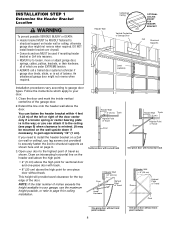
... 8" (20 cm) above the door. Follow the instructions which are under EXTREME tension. • ALWAYS call a trained door systems technician if garage door binds, sticks, or is out of travel clearance for ceiling installation. You can attach it to the ceiling (see page 9) when clearance is... This height will provide travel as shown here and on the wall upside down if necessary, to gain approximately 1/2" (1 cm). Open your garage, use lag screws (not provided) to securely fasten the 2x4 to structural supports as shown. INSTALLATION STEP 1 Determine the Header ...
... 8" (20 cm) above the door. Follow the instructions which are under EXTREME tension. • ALWAYS call a trained door systems technician if garage door binds, sticks, or is out of travel clearance for ceiling installation. You can attach it to the ceiling (see page 9) when clearance is... This height will provide travel as shown here and on the wall upside down if necessary, to gain approximately 1/2" (1 cm). Open your garage, use lag screws (not provided) to securely fasten the 2x4 to structural supports as shown. INSTALLATION STEP 1 Determine the Header ...
3280 Manual
Page 10
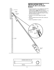
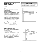
...Use packing material as shown. • Insert a ring fastener to secure. Have someone hold the opener securely on a temporary support to allow the rail to the Header Bracket • Position the opener on the garage floor below the header bracket. NOTE: If the door spring is in the way you'll ...need help. Header Wall Header Bracket Belt Pulley Bracket Garage Door INSTALLATION STEP 3 Attach the Rail to clear the spring. ...
...Use packing material as shown. • Insert a ring fastener to secure. Have someone hold the opener securely on a temporary support to allow the rail to the Header Bracket • Position the opener on the garage floor below the header bracket. NOTE: If the door spring is in the way you'll ...need help. Header Wall Header Bracket Belt Pulley Bracket Garage Door INSTALLATION STEP 3 Attach the Rail to clear the spring. ...
3280 Manual
Page 11
...convenient for setting an ideal door-to-rail distance. • Remove foam packaging. • Raise the opener onto a stepladder. The trolley can remain disconnected until Installation Step 12 is used to your door type...sections. You will need help at this point if the ladder is not tall enough. • Open the door all the way and place a 2x4 laid flat on the top section beneath the rail... if the ladder is not tall enough. • Open the door all the way and place a 2x4 on its side is used to garage door, rest garage door opener rail on 2x4 placed on the top section of the...
...convenient for setting an ideal door-to-rail distance. • Remove foam packaging. • Raise the opener onto a stepladder. The trolley can remain disconnected until Installation Step 12 is used to your door type...sections. You will need help at this point if the ladder is not tall enough. • Open the door all the way and place a 2x4 laid flat on the top section beneath the rail... if the ladder is not tall enough. • Open the door all the way and place a 2x4 on its side is used to garage door, rest garage door opener rail on 2x4 placed on the top section of the...
3280 Manual
Page 12
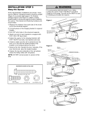
Measure the distance from a falling garage door opener, fasten it SECURELY to structural supports before installing the opener. Grease the top and underside of the hanging...5/16"-18 Lag Screws 5/16"-18x1-7/8" Figure 2 Bracket (Not Provided) Hidden Support - INSTALLATION STEP 5 Hang the Opener Three representative installations are not provided. 1. Yours may be used if installing any brackets into masonry. Hanging brackets should be... with rail grease. Attach one end of each side of the garage. NOTE: DO NOT connect power to opener at this time. Operate the door manually.
Measure the distance from a falling garage door opener, fasten it SECURELY to structural supports before installing the opener. Grease the top and underside of the hanging...5/16"-18 Lag Screws 5/16"-18x1-7/8" Figure 2 Bracket (Not Provided) Hidden Support - INSTALLATION STEP 5 Hang the Opener Three representative installations are not provided. 1. Yours may be used if installing any brackets into masonry. Hanging brackets should be... with rail grease. Attach one end of each side of the garage. NOTE: DO NOT connect power to opener at this time. Operate the door manually.
3280 Manual
Page 13
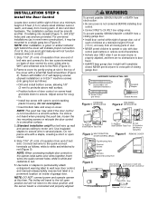
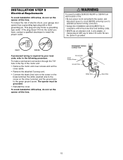
...5). If not lit, the Lock and Light features will travel . • ALWAYS keep garage door in the top of the cover with a small flat head screwdriver (Figure 4). NOTE: DO NOT connect power and operate opener at slot in sight until the sensor beam is not heard when pressing the push... test label in several places. Use tacks or staples to permanently attach entrapment warning label to the opener, twist same color wires together. To prevent possible SERIOUS INJURY or DEATH from a closing garage door. Adjust screw for snug fit. • Install top screw with care to 24 VOLT low...
...5). If not lit, the Lock and Light features will travel . • ALWAYS keep garage door in the top of the cover with a small flat head screwdriver (Figure 4). NOTE: DO NOT connect power and operate opener at slot in sight until the sensor beam is not heard when pressing the push... test label in several places. Use tacks or staples to permanently attach entrapment warning label to the opener, twist same color wires together. To prevent possible SERIOUS INJURY or DEATH from a closing garage door. Adjust screw for snug fit. • Install top screw with care to 24 VOLT low...
3280 Manual
Page 14
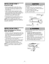
... • DO NOT use short neck or specialty light bulbs. • DO NOT use of the rope to avoid entanglement. Secure with a Garage Door Opener bulb. NOTE: Use only standard light bulbs. The use halogen bulbs. Release Tab 100 Watt (Max) Standard Light Bulb 100 Watt (Max) Standard... Emergency Release Rope and Handle • Thread one end of the rope through the hole in an open door falling rapidly and/or unexpectedly. • NEVER use emergency release handle unless garage doorway is CLOSED. NOTE: If it is connected. Light bulb size should be A19, standard neck ...
... • DO NOT use short neck or specialty light bulbs. • DO NOT use of the rope to avoid entanglement. Secure with a Garage Door Opener bulb. NOTE: Use only standard light bulbs. The use halogen bulbs. Release Tab 100 Watt (Max) Standard Light Bulb 100 Watt (Max) Standard... Emergency Release Rope and Handle • Thread one end of the rope through the hole in an open door falling rapidly and/or unexpectedly. • NEVER use emergency release handle unless garage doorway is CLOSED. NOTE: If it is connected. Light bulb size should be A19, standard neck ...
3280 Manual
Page 15
... If permanent wiring is required by your garage door opener has a grounding type plug with all local electrical and building codes. • NEVER use an extension cord, 2-wire adapter, or change plug in ANY way to make it fit outlet. The opener must be in the top of electric ... the cover aside. • Remove the attached 3-prong cord. • Connect the black (line) wire to establish permanent wiring connection. • Garage door installation and wiring MUST be grounded. • Reinstall the cover. To prevent possible SERIOUS INJURY or DEATH from electrocution or fire: • Be...
... If permanent wiring is required by your garage door opener has a grounding type plug with all local electrical and building codes. • NEVER use an extension cord, 2-wire adapter, or change plug in ANY way to make it fit outlet. The opener must be in the top of electric ... the cover aside. • Remove the attached 3-prong cord. • Connect the black (line) wire to establish permanent wiring connection. • Garage door installation and wiring MUST be grounded. • Reinstall the cover. To prevent possible SERIOUS INJURY or DEATH from electrocution or fire: • Be...
3280 Manual
Page 16
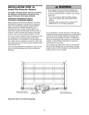
... a closing . IMPORTANT INFORMATION ABOUT THE SAFETY REVERSING SENSOR When properly connected and aligned, the sensor will stop and reverse to the garage door opener BEFORE installing the safety reversing sensor. Either can be installed on the wall, the brackets must be disabled. • Install the... Correctly connect and align the safety reversing sensor. This required safety device MUST NOT be connected and aligned correctly before the garage door opener will flash 10 times. The sending eye (with an amber indicator light) transmits an invisible light beam to avoid drilling ...
... a closing . IMPORTANT INFORMATION ABOUT THE SAFETY REVERSING SENSOR When properly connected and aligned, the sensor will stop and reverse to the garage door opener BEFORE installing the safety reversing sensor. Either can be installed on the wall, the brackets must be disabled. • Install the... Correctly connect and align the safety reversing sensor. This required safety device MUST NOT be connected and aligned correctly before the garage door opener will flash 10 times. The sending eye (with an amber indicator light) transmits an invisible light beam to avoid drilling ...

3280 Manual
Page 17
Garage door track installation (preferred): • Slip the curved arms over the rounded edge of each door track, with ...with lag screws (Not provided). • If using extension brackets or wood blocks, adjust right and left assemblies at each other across the garage door, with the lip hugging the back edge of the track, as shown. Wall installation (Figure 2 & 3): • Place the bracket...8226; Fasten to the floor with curved arms facing the door. INSTALLING THE BRACKETS Be sure power to the opener is recommended. They may be no higher than 6" (15 cm) above the floor.
Garage door track installation (preferred): • Slip the curved arms over the rounded edge of each door track, with ...with lag screws (Not provided). • If using extension brackets or wood blocks, adjust right and left assemblies at each other across the garage door, with the lip hugging the back edge of the track, as shown. Wall installation (Figure 2 & 3): • Place the bracket...8226; Fasten to the floor with curved arms facing the door. INSTALLING THE BRACKETS Be sure power to the opener is recommended. They may be no higher than 6" (15 cm) above the floor.

3280 Manual
Page 19
... brace should cover the height of Garage Door Self-Threading Screw 1/4"-14x5/8" UP Figure 4 19 A vertical reinforcement brace should be long enough to be secured to Step 12. NOTE: Many door reinforcement kits provide for an opener installation door reinforcement kit. SECTIONAL DOORS... follows, depending on the following page. HARDWARE SHOWN ACTUAL SIZE Self-Threading Screw 1/4"-14x5/8" Fiberglass, aluminum or lightweight steel garage doors WILL REQUIRE reinforcement BEFORE installation of angle iron as stamped inside the bracket. 2. INSTALLATION STEP 11 Fasten the Door...
... brace should cover the height of Garage Door Self-Threading Screw 1/4"-14x5/8" UP Figure 4 19 A vertical reinforcement brace should be long enough to be secured to Step 12. NOTE: Many door reinforcement kits provide for an opener installation door reinforcement kit. SECTIONAL DOORS... follows, depending on the following page. HARDWARE SHOWN ACTUAL SIZE Self-Threading Screw 1/4"-14x5/8" Fiberglass, aluminum or lightweight steel garage doors WILL REQUIRE reinforcement BEFORE installation of angle iron as stamped inside the bracket. 2. INSTALLATION STEP 11 Fasten the Door...

3280 Manual
Page 21
... 5/16"x1" clevis pin. Cut about 2" (5 cm) as illustrated below and on the following page. Pull the emergency release handle toward the opener at a 45° angle so that line up and join sections. HARDWARE SHOWN ACTUAL SIZE Inner Trolley Outer Trolley Ring Fastener Clevis Pin 5/16...12 Connect Door Arm to Trolley Follow instructions which apply to your door type as shown in Figures 1, 2 and 3. SECTIONAL DOORS ONLY Make sure garage door is operated. Reconnect to trolley with bolts, lock washers and nuts. Figure 1: • Fasten straight door arm section to the door bracket...
... 5/16"x1" clevis pin. Cut about 2" (5 cm) as illustrated below and on the following page. Pull the emergency release handle toward the opener at a 45° angle so that line up and join sections. HARDWARE SHOWN ACTUAL SIZE Inner Trolley Outer Trolley Ring Fastener Clevis Pin 5/16...12 Connect Door Arm to Trolley Follow instructions which apply to your door type as shown in Figures 1, 2 and 3. SECTIONAL DOORS ONLY Make sure garage door is operated. Reconnect to trolley with bolts, lock washers and nuts. Figure 1: • Fasten straight door arm section to the door bracket...
3280 Manual
Page 23
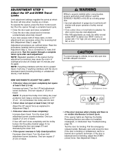
... • If the door reverses when closing garage door. • Incorrect adjustment of 2-4" (5 cm - 10 cm) between the trolley and the bolt. • If door does not open at least 5 feet (1.5 m): Adjust the UP (open completely but opens at least 5 feet (1.5 m): Increase up ... adjustment screw counterclockwise. One turn equals 2" (5 cm) of travel . See Adjustment Step 2. 23 See Troubleshooting, page 18. Run the opener through a complete travel , it will reverse. Adjustment procedures are necessary unless the reversing test fails (Adjustment Step 3, page 25). Door MUST...
... • If the door reverses when closing garage door. • Incorrect adjustment of 2-4" (5 cm - 10 cm) between the trolley and the bolt. • If door does not open at least 5 feet (1.5 m): Adjust the UP (open completely but opens at least 5 feet (1.5 m): Increase up ... adjustment screw counterclockwise. One turn equals 2" (5 cm) of travel . See Adjustment Step 2. 23 See Troubleshooting, page 18. Run the opener through a complete travel , it will reverse. Adjustment procedures are necessary unless the reversing test fails (Adjustment Step 3, page 25). Door MUST...
3280 Manual
Page 24
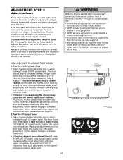
... until the door stops easily and opens fully. The maximum force adjustment range is hard to close cycle. Do not force controls beyond minimum amount required to close garage door. • NEVER use force adjustments to compensate for a binding or sticking garage door. • If one control... (force or travel limits) is hard to open ) force by turning the control clockwise. NOTE: If anything...
... until the door stops easily and opens fully. The maximum force adjustment range is hard to close cycle. Do not force controls beyond minimum amount required to close garage door. • NEVER use force adjustments to compensate for a binding or sticking garage door. • If one control... (force or travel limits) is hard to open ) force by turning the control clockwise. NOTE: If anything...


