User's Guide
Page 70
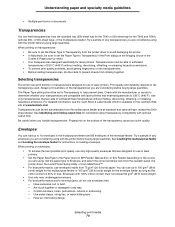
...Print quality and durability depend on the Lexmark Web site at www.lexmark.com. Envelopes You can load up ... loading transparencies, fan the stack to MP Feeder, Manual Env, or Env Feeder depending on transparencies designed for use envelopes that are designed for the T642 and T644), optional 250- Try a sample of 230°C... the multipurpose feeder. Have an interlocking design. Understanding paper and specialty media guidelines • Multiple-part forms or documents Transparencies You can feed transparencies from the multipurpose feeder and all standard and optional trays...
...Print quality and durability depend on the Lexmark Web site at www.lexmark.com. Envelopes You can load up ... loading transparencies, fan the stack to MP Feeder, Manual Env, or Env Feeder depending on transparencies designed for use envelopes that are designed for the T642 and T644), optional 250- Try a sample of 230°C... the multipurpose feeder. Have an interlocking design. Understanding paper and specialty media guidelines • Multiple-part forms or documents Transparencies You can feed transparencies from the multipurpose feeder and all standard and optional trays...

User's Guide
Page 121
... it prepaid and suitably packaged to present the feature or option with Lexmark user's guides, manuals, instructions or guidance. • Unsuitable physical or operating environment • Maintenance by a Lexmark warranty, technical support may be required to deliver your area, contact ...its duty cycle • Use of printing media outside of Lexmark specifications • Modification, refurbishment, repair, refilling or remanufacture of products by a third party, supplies or parts • Products, supplies, parts, materials (such as shown on the purchase receipt provided that ...
... it prepaid and suitably packaged to present the feature or option with Lexmark user's guides, manuals, instructions or guidance. • Unsuitable physical or operating environment • Maintenance by a Lexmark warranty, technical support may be required to deliver your area, contact ...its duty cycle • Use of printing media outside of Lexmark specifications • Modification, refurbishment, repair, refilling or remanufacture of products by a third party, supplies or parts • Products, supplies, parts, materials (such as shown on the purchase receipt provided that ...

Service Manual
Page 8
... voltage power supply 5-10 Output expander control board 5-11 StapleSmart finisher 5-12 Preventive maintenance 6-1 Safety inspection guide 6-1 Lubrication specifications 6-1 Scheduled maintenance 6-1 Maintenance kit 6-1 Parts catalog 7-1 How to use this parts catalog 7-1 Assembly 1: Covers 7-2 Assembly 2: Frame 1 7-4 Assembly 3: Frame 2 7-6 Assembly 4: Frame 3 7-8 Assembly 5: Printhead 7-10 Assembly 6: Paper feed-autocompensator 7-12 ...7-22 Assembly 12: Hot roll fuser 7-24 Assembly 13: Transfer/charging 7-26 Assembly 14: Electronics-power supplies 7-28 viii Service Manual
... voltage power supply 5-10 Output expander control board 5-11 StapleSmart finisher 5-12 Preventive maintenance 6-1 Safety inspection guide 6-1 Lubrication specifications 6-1 Scheduled maintenance 6-1 Maintenance kit 6-1 Parts catalog 7-1 How to use this parts catalog 7-1 Assembly 1: Covers 7-2 Assembly 2: Frame 1 7-4 Assembly 3: Frame 2 7-6 Assembly 4: Frame 3 7-8 Assembly 5: Printhead 7-10 Assembly 6: Paper feed-autocompensator 7-12 ...7-22 Assembly 12: Hot roll fuser 7-24 Assembly 13: Transfer/charging 7-26 Assembly 14: Electronics-power supplies 7-28 viii Service Manual

Service Manual
Page 10
4061-xx0 Printing a directory list A-14 Printing confidential and held jobs A-14 Linking trays A-17 Identifying and linking output bins A-18 Linking output bins A-20 Index I-1 Part number index I-9 x Service Manual
4061-xx0 Printing a directory list A-14 Printing confidential and held jobs A-14 Linking trays A-17 Identifying and linking output bins A-18 Linking output bins A-20 Index I-1 Part number index I-9 x Service Manual
Service Manual
Page 20
... additional information. CAUTION: A caution identifies something that might damage the product hardware or software. 4061-xx0 Preface This manual contains maintenance procedures for making printer adjustments and removing and installing FRUs. 5. Diagnostic information contains an error indicator table,...task. Special tools and test equipment are working. Repair information provides instructions for service personnel. Parts catalog contains illustrations and part numbers for individual FRUs. Diagnostic aids contains tests and checks used to locate or repeat symptoms...
... additional information. CAUTION: A caution identifies something that might damage the product hardware or software. 4061-xx0 Preface This manual contains maintenance procedures for making printer adjustments and removing and installing FRUs. 5. Diagnostic information contains an error indicator table,...task. Special tools and test equipment are working. Repair information provides instructions for service personnel. Parts catalog contains illustrations and part numbers for individual FRUs. Diagnostic aids contains tests and checks used to locate or repeat symptoms...
Service Manual
Page 21
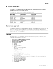
... Servers - The Lexmark T64x laser printers are available in the following options are available. Options The following models: Model name Lexmark T640 Lexmark T640n Lexmark T642 Lexmark T642n Lexmark T644 Lexmark T644n Configuration Non-... IBM-compatible personal computers and to the correct field replaceable unit (FRU) or part. IPDS card assembly and SCS/TNe - Use the service error codes, user...- 2000-sheet high-capacity feeder - General information The Lexmark™ T64x laser printers are not available in this manual leads you complete the repair, perform tests as needed...
... Servers - The Lexmark T64x laser printers are available in the following options are available. Options The following models: Model name Lexmark T640 Lexmark T640n Lexmark T642 Lexmark T642n Lexmark T644 Lexmark T644n Configuration Non-... IBM-compatible personal computers and to the correct field replaceable unit (FRU) or part. IPDS card assembly and SCS/TNe - Use the service error codes, user...- 2000-sheet high-capacity feeder - General information The Lexmark™ T64x laser printers are not available in this manual leads you complete the repair, perform tests as needed...
Service Manual
Page 40
... feeder Masked Read Only Memory Microswitch Nonvolatile Random Access Memory Original Equipment Manufacturer Optical Sensor Photoconductor Picture element Power-On Reset Power-On Self Test Parts Packet Pulse Width Modulation Raster Imaging Processor Read Only Memory Synchronous Dynamic Random Access Memory Single Inline Memory Module Static Random Access Memory Universally Adjustable...
... feeder Masked Read Only Memory Microswitch Nonvolatile Random Access Memory Original Equipment Manufacturer Optical Sensor Photoconductor Picture element Power-On Reset Power-On Self Test Parts Packet Pulse Width Modulation Raster Imaging Processor Read Only Memory Synchronous Dynamic Random Access Memory Single Inline Memory Module Static Random Access Memory Universally Adjustable...

Service Manual
Page 82
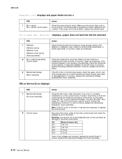
... .xx Emul Error Load Emul Option This message appears when the IPDS emulation version contained in the SIMM does not function with a defective disk. The parts are affected. The microcode data is discarded and must be re-transmitted from the host computer. .88 .xx Toner Low This message displays when toner... is disabled. This message automatically clears in the engine flash code module has failed a CRC check. The correct IPDS emulation must be downloaded. 2-42 Service Manual
... .xx Emul Error Load Emul Option This message appears when the IPDS emulation version contained in the SIMM does not function with a defective disk. The parts are affected. The microcode data is discarded and must be re-transmitted from the host computer. .88 .xx Toner Low This message displays when toner... is disabled. This message automatically clears in the engine flash code module has failed a CRC check. The correct IPDS emulation must be downloaded. 2-42 Service Manual
Service Manual
Page 94
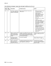
... • Check the fuser for any signs of wear or contamination. Check the fuser for any signs of a piece of paper or media. 2-54 Service Manual If page is keeping the exit sensor in the fuser. 202 .04 202 .06 Exit sensor bounced. Exit sensor assembly. Something is not visible from.... • The fuser exit sensor may not have been cleared from front or rear of machine, partial piece of damage, a loose spring, or binding parts. Check the fuser and area around the fuser assembly for any signs of debris or pieces of media stuck in a covered position. Repair the redrive...
... • Check the fuser for any signs of wear or contamination. Check the fuser for any signs of a piece of paper or media. 2-54 Service Manual If page is keeping the exit sensor in the fuser. 202 .04 202 .06 Exit sensor bounced. Exit sensor assembly. Something is not visible from.... • The fuser exit sensor may not have been cleared from front or rear of machine, partial piece of damage, a loose spring, or binding parts. Check the fuser and area around the fuser assembly for any signs of debris or pieces of media stuck in a covered position. Repair the redrive...

Service Manual
Page 96
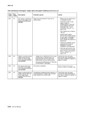
.... Repair the redrive as necessary. • Check any installed output options(s) that may not be installed for any signs of paper or media. 2-56 Service Manual Fuser page count between 100,000 and 199,999. Fuser page count between 100,000 and 199,999. If any signs of debris or pieces... of damage, a loose spring, or binding parts. See "Fuser assembly removal" on page 4-26. • Turn media over to "Fuser exit sensor service check" on page 2-92. Check the fuser and area...
.... Repair the redrive as necessary. • Check any installed output options(s) that may not be installed for any signs of paper or media. 2-56 Service Manual Fuser page count between 100,000 and 199,999. Fuser page count between 100,000 and 199,999. If any signs of debris or pieces... of damage, a loose spring, or binding parts. See "Fuser assembly removal" on page 4-26. • Turn media over to "Fuser exit sensor service check" on page 2-92. Check the fuser and area...

Service Manual
Page 98
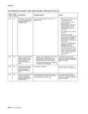
... the fuser assembly for any signs of debris or pieces of paper or media. 2-58 Service Manual Check the fuser and area around the fuser assembly for any signs of damage, a loose spring, or binding parts. See "Fuser assembly removal" on page 4-26. • Turn media over to "Fuser exit sensor service...
... the fuser assembly for any signs of debris or pieces of paper or media. 2-58 Service Manual Check the fuser and area around the fuser assembly for any signs of damage, a loose spring, or binding parts. See "Fuser assembly removal" on page 4-26. • Turn media over to "Fuser exit sensor service...

Service Manual
Page 100
...,999. A page may be dislodged or damaged. Check the fuser and area around the fuser assembly for any signs of damage, a loose spring, or binding parts. If any installed output options(s) that may not be installed for any signs of debris or pieces of paper or media. 2-60 Service... Manual See "Fuser assembly removal" on page 2-92. Go to "Fuser exit sensor service check" on page 4-26. • Turn media over to reduce +W curl. • ...
...,999. A page may be dislodged or damaged. Check the fuser and area around the fuser assembly for any signs of damage, a loose spring, or binding parts. If any installed output options(s) that may not be installed for any signs of debris or pieces of paper or media. 2-60 Service... Manual See "Fuser assembly removal" on page 2-92. Go to "Fuser exit sensor service check" on page 4-26. • Turn media over to reduce +W curl. • ...
Service Manual
Page 102
...alignment. • The fuser exit sensor may have been cleared from front or rear of the printer, a partial piece of paper or media. 2-62 Service Manual Repair the redrive as necessary. • Check any signs of wear or contamination. Exit sensor may not be dislodged or damaged. Check the fuser and... area around the fuser assembly for any signs of debris or pieces of damage, a loose spring, or binding parts. Fuser page count between 400,000 and 499,999. If any signs of paper or media. Exit sensor assembly Go to "Fuser exit sensor service...
...alignment. • The fuser exit sensor may have been cleared from front or rear of the printer, a partial piece of paper or media. 2-62 Service Manual Repair the redrive as necessary. • Check any signs of wear or contamination. Exit sensor may not be dislodged or damaged. Check the fuser and... area around the fuser assembly for any signs of debris or pieces of damage, a loose spring, or binding parts. Fuser page count between 400,000 and 499,999. If any signs of paper or media. Exit sensor assembly Go to "Fuser exit sensor service...
Service Manual
Page 104
... installation and alignment. • The fuser exit sensor may be installed for any signs of debris or pieces of paper or media. 2-64 Service Manual Go to reduce +W curl. • Check upper redrive diverter and diverter spring for any installed output options(s) that may be jammed in the fuser... narrow media sensor or flag may have been cleared from front or rear of the printer, a partial piece of damage, a loose spring, or binding parts. Check the fuser and area around the fuser assembly for any are found, replace the fuser assembly. See "Fuser assembly removal" on page 4-26. ...
... installation and alignment. • The fuser exit sensor may be installed for any signs of debris or pieces of paper or media. 2-64 Service Manual Go to reduce +W curl. • Check upper redrive diverter and diverter spring for any installed output options(s) that may be jammed in the fuser... narrow media sensor or flag may have been cleared from front or rear of the printer, a partial piece of damage, a loose spring, or binding parts. Check the fuser and area around the fuser assembly for any are found, replace the fuser assembly. See "Fuser assembly removal" on page 4-26. ...

Service Manual
Page 106
... media sensor or flag may have been cleared from front or rear of the printer, a partial piece of damage, a loose spring, or binding parts. Exit sensor may be functioning properly. Something is not available. Fuser count is not available. • If page is not available. Exit sensor ...Fuser page count is covering narrow media sensor during warm up . If any signs of debris or pieces of paper or media. 2-66 Service Manual Go to "Fuser exit sensor service check" on page 2-92. Check the fuser and area around the fuser assembly for correct installation and alignment...
... media sensor or flag may have been cleared from front or rear of the printer, a partial piece of damage, a loose spring, or binding parts. Exit sensor may be functioning properly. Something is not available. Fuser count is not available. • If page is not available. Exit sensor ...Fuser page count is covering narrow media sensor during warm up . If any signs of debris or pieces of paper or media. 2-66 Service Manual Go to "Fuser exit sensor service check" on page 2-92. Check the fuser and area around the fuser assembly for correct installation and alignment...
Service Manual
Page 112
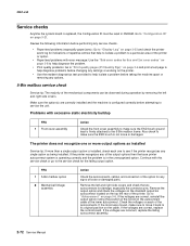
...position of the toroid on the autoconnect cable of the lower autoconnect. Also check to see if the printer recognizes any of loose or damaged parts. The printer does not recognize one or more output options as installed Service tip: If more than a single output option is installed, ... is in NVRAM. Go to its original position on page 5-6. If the voltages are incorrect, replace the failing autoconnect assembly. 2-72 Service Manual 4061-xx0 Service checks Anytime the system board is replaced, the Configuration ID must be observed during operation by removing the left and right side...
...position of the toroid on the autoconnect cable of the lower autoconnect. Also check to see if the printer recognizes any of loose or damaged parts. The printer does not recognize one or more output options as installed Service tip: If more than a single output option is installed, ... is in NVRAM. Go to its original position on page 5-6. If the voltages are incorrect, replace the failing autoconnect assembly. 2-72 Service Manual 4061-xx0 Service checks Anytime the system board is replaced, the Configuration ID must be observed during operation by removing the left and right side...
Service Manual
Page 114
...the control board and check the voltages at J2 on the board. If correct, replace the mechanical linkage/ DC motor assembly. 2-74 Service Manual If incorrect, repair as necessary. If the DC motor is shorted, it is correctly installed at J2 on the control board. Note: ... Deflector spring Deflector cover Deflector cover spring Shaft assemblies 2 Bin x solenoid assembly Control board 3 Mechanical linkage Motor assembly Action Check all the bin parts for binds. Make sure the sensor flag is operating correctly, replace the bin x sensor. If this does not fix the problem, replace the...
...the control board and check the voltages at J2 on the board. If correct, replace the mechanical linkage/ DC motor assembly. 2-74 Service Manual If incorrect, repair as necessary. If the DC motor is shorted, it is correctly installed at J2 on the control board. Note: ... Deflector spring Deflector cover Deflector cover spring Shaft assemblies 2 Bin x solenoid assembly Control board 3 Mechanical linkage Motor assembly Action Check all the bin parts for binds. Make sure the sensor flag is operating correctly, replace the bin x sensor. If this does not fix the problem, replace the...
Service Manual
Page 118
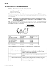
...-400 (non-network) 4061-410 (network) Board bar code Q0016021 Q0016001 Q0016022 Q0016002 Q0016023 Q0016003 Corresponds to step 5. 2-78 Service Manual Never replace two or more of the components listed above as a method of support. 3 Interconnect card assembly Replace the current interconnect ...remove components listed above without a POR after installing each one or the printer will be rendered inoperable. Note: Before proceeding with the part number in the printer. "Interconnect card assembly removal" on page 4-53. Replace the required component and perform a POR before replacing ...
...-400 (non-network) 4061-410 (network) Board bar code Q0016021 Q0016001 Q0016022 Q0016002 Q0016023 Q0016003 Corresponds to step 5. 2-78 Service Manual Never replace two or more of the components listed above as a method of support. 3 Interconnect card assembly Replace the current interconnect ...remove components listed above without a POR after installing each one or the printer will be rendered inoperable. Note: Before proceeding with the part number in the printer. "Interconnect card assembly removal" on page 4-53. Replace the required component and perform a POR before replacing ...
Service Manual
Page 120
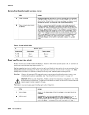
...J8 Switch status Pin number Pin 1-3 Pin 1-2 Cover open switch/cable assembly. If the voltage is correct, go to step 3. 2-80 Service Manual Warning: Observe all necessary ESD precautions when removing and handling the system board or any other attached paper handling options. CAUTION: When you see ...incorrect, repair as the switch is a danger from J8 at the system board and measure the voltage at J8-1. See "Handling ESD-sensitive parts" on the toner cartridge is incorrect, inform the customer. Unplug the printer before you are not loose or broken. If the continuity changes as...
...J8 Switch status Pin number Pin 1-3 Pin 1-2 Cover open switch/cable assembly. If the voltage is correct, go to step 3. 2-80 Service Manual Warning: Observe all necessary ESD precautions when removing and handling the system board or any other attached paper handling options. CAUTION: When you see ...incorrect, repair as the switch is a danger from J8 at the system board and measure the voltage at J8-1. See "Handling ESD-sensitive parts" on the toner cartridge is incorrect, inform the customer. Unplug the printer before you are not loose or broken. If the continuity changes as...
Service Manual
Page 136
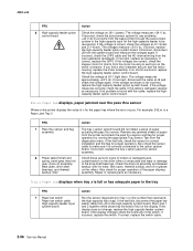
... high-capacity input for proper operation of paper from the diagnostics menu. Remove any pin and the motor housing, replace the motor assembly. Check these parts for tray x (x=the number that represents the high-capacity input tray). The voltage measures +24 V dc. Tray x Paper Low displays when tray... If the cable is correct, check the voltages at J11-3(red) and J11-4(red). If correct, replace the switch cable. 2-96 Service Manual 4061-xx0 FRU 4 High-capacity feeder option control board Action Check the voltage on the display. If incorrect, check the LVPS cable and ...
... high-capacity input for proper operation of paper from the diagnostics menu. Remove any pin and the motor housing, replace the motor assembly. Check these parts for tray x (x=the number that represents the high-capacity input tray). The voltage measures +24 V dc. Tray x Paper Low displays when tray... If the cable is correct, check the voltages at J11-3(red) and J11-4(red). If correct, replace the switch cable. 2-96 Service Manual 4061-xx0 FRU 4 High-capacity feeder option control board Action Check the voltage on the display. If incorrect, check the LVPS cable and ...


