Service Manual
Page 3
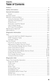
... Tables 2-2 Service Checks 2-5 First Print Line Service Check 2-5 Maintenance Station Service Check 2-6 LCD Assembly Display Service Check 2-7 Paper Feed Service Check 2-8 Paper Path Service Check 2-10 CompactFlash/SmartMedia Service Check 2-11 Power Service Check 2-11 Print Quality Service Check 2-12 Transport Service Check 2-14 Diagnostic Aids 3-1 Paper Pick Assembly Operation 3-1 Diagnostic Mode 3-1 Code Level 3-2 LCD Test 3-2 Button Test 3-2 CompactFlash Test 3-3 SmartMedia Test 3-3 SmartMedia Write Protect Test 3-3 DRAM Test 3-4 Access Cover Sensor Test 3-4 iii
... Tables 2-2 Service Checks 2-5 First Print Line Service Check 2-5 Maintenance Station Service Check 2-6 LCD Assembly Display Service Check 2-7 Paper Feed Service Check 2-8 Paper Path Service Check 2-10 CompactFlash/SmartMedia Service Check 2-11 Power Service Check 2-11 Print Quality Service Check 2-12 Transport Service Check 2-14 Diagnostic Aids 3-1 Paper Pick Assembly Operation 3-1 Diagnostic Mode 3-1 Code Level 3-2 LCD Test 3-2 Button Test 3-2 CompactFlash Test 3-3 SmartMedia Test 3-3 SmartMedia Write Protect Test 3-3 DRAM Test 3-4 Access Cover Sensor Test 3-4 iii
Service Manual
Page 4
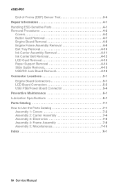
...Sensor Test 3-4 Repair Information 4-1 Handling ESD-Sensitive Parts 4-1 Removal Procedures 4-2 Covers 4-2 Button Card Removal 4-7 Engine Board Removal 4-8 Engine Frame Assembly Removal 4-9 Exit Tray Removal 4-10 Ink Carrier Assembly Removal 4-11 Ink Carrier Belt Removal 4-12 LCD Card Removal 4-13 Paper Support Removal 4-14 Slide Guide Removal 4-15 USB/DC Jack Board Removal 4-16 Connector Locations 5-1 Engine Board Connectors 5-1 LCD Board Connectors 5-3 USB PSB/Power Board Connector 5-4 Preventive Maintenance 6-1 Lubrication Specifications 6-1 Parts Catalog 7-1 How to Use...
...Sensor Test 3-4 Repair Information 4-1 Handling ESD-Sensitive Parts 4-1 Removal Procedures 4-2 Covers 4-2 Button Card Removal 4-7 Engine Board Removal 4-8 Engine Frame Assembly Removal 4-9 Exit Tray Removal 4-10 Ink Carrier Assembly Removal 4-11 Ink Carrier Belt Removal 4-12 LCD Card Removal 4-13 Paper Support Removal 4-14 Slide Guide Removal 4-15 USB/DC Jack Board Removal 4-16 Connector Locations 5-1 Engine Board Connectors 5-1 LCD Board Connectors 5-3 USB PSB/Power Board Connector 5-4 Preventive Maintenance 6-1 Lubrication Specifications 6-1 Parts Catalog 7-1 How to Use...
Service Manual
Page 5
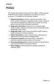
... description of printer problems. 4. Repair Information provides instructions for individual FRUs. Parts Catalog contains illustrations and part numbers for making printer adjustments and removing and installing FRUs. 5. Preface v Connector Locations uses illustrations to prevent problems. 7. Preventive Maintenance contains the lubrication specifications and recommendations to identify the connector locations and test points on the printer. 6. Diagnostic Information contains an error indicator table, symptom tables, and service checks used to isolate failing field replaceable units...
... description of printer problems. 4. Repair Information provides instructions for individual FRUs. Parts Catalog contains illustrations and part numbers for making printer adjustments and removing and installing FRUs. 5. Preface v Connector Locations uses illustrations to prevent problems. 7. Preventive Maintenance contains the lubrication specifications and recommendations to identify the connector locations and test points on the printer. 6. Diagnostic Information contains an error indicator table, symptom tables, and service checks used to isolate failing field replaceable units...
Service Manual
Page 11
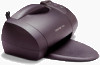
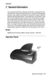
... using the Windows 98 operating system. Also note that there is a handle molded into the covers. 4102-P01 1. The photoprinter incorporates a new photo control operator panel into the printer near the top of the access cover under the translucent cover. Model KODAK Personal Picture Maker 120 by Lexmark - 4102-P01 Operator Panel . Camera memory cards have been incorporated into the cover set and slots to be a small personal inkjet printer specifically...
... using the Windows 98 operating system. Also note that there is a handle molded into the covers. 4102-P01 1. The photoprinter incorporates a new photo control operator panel into the printer near the top of the access cover under the translucent cover. Model KODAK Personal Picture Maker 120 by Lexmark - 4102-P01 Operator Panel . Camera memory cards have been incorporated into the cover set and slots to be a small personal inkjet printer specifically...
Service Manual
Page 12
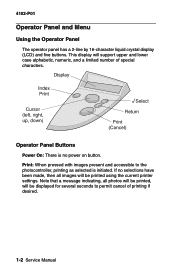
... images present and accessible to permit cancel of special characters. Note that a message indicating, all images will support upper and lower case alphabetic, numeric, and a limited number of printing if desired. 1-2 Service Manual This display will be displayed for several seconds to the photocontroller, printing as selected is no selections have been made, then all photos will be printed, will be printed using the current printer settings. Operator Panel Buttons Power...
... images present and accessible to permit cancel of special characters. Note that a message indicating, all images will support upper and lower case alphabetic, numeric, and a limited number of printing if desired. 1-2 Service Manual This display will be displayed for several seconds to the photocontroller, printing as selected is no selections have been made, then all photos will be printed, will be printed using the current printer settings. Operator Panel Buttons Power...
Service Manual
Page 15
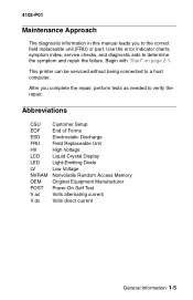
... Crystal Display Light-Emitting Diode Low Voltage Nonvolatile Random Access Memory Original Equipment Manufacturer Power-On Self Test Volts alternating current Volts direct current General Information 1-5 After you to the correct field replaceable unit (FRU) or part. 4102-P01 Maintenance Approach The diagnostic information in this manual leads you complete the repair, perform tests as needed to verify the repair. Use the error indicator charts, symptom index, service checks, and...
... Crystal Display Light-Emitting Diode Low Voltage Nonvolatile Random Access Memory Original Equipment Manufacturer Power-On Self Test Volts alternating current Volts direct current General Information 1-5 After you to the correct field replaceable unit (FRU) or part. 4102-P01 Maintenance Approach The diagnostic information in this manual leads you complete the repair, perform tests as needed to verify the repair. Use the error indicator charts, symptom index, service checks, and...
Service Manual
Page 17
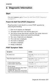
... turn Go to the "Paper Feed Service Check" on page 2-8. • Carrier does not move • Carrier slams side frame Go to the "Transport Service Check" on page 2-14. • Blank display • All diamonds displayed after POST • Display difficult to read • Display OK, buttons do not function • One or more buttons do not function Go to "Power-On-Self-Test (POST) Sequence" on page 2-1. The code level is displayed...
... turn Go to the "Paper Feed Service Check" on page 2-8. • Carrier does not move • Carrier slams side frame Go to the "Transport Service Check" on page 2-14. • Blank display • All diamonds displayed after POST • Display difficult to read • Display OK, buttons do not function • One or more buttons do not function Go to "Power-On-Self-Test (POST) Sequence" on page 2-1. The code level is displayed...
Service Manual
Page 18
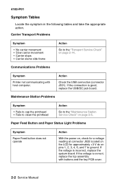
... • Carrier slams side frame Action Go to the "Transport Service Check" on pins 1, 2, 3, 4, 6, and 7 to the "Maintenance Station Service Check" on page 2-6. Action Check the USB connection (connector J601). Communications Problems Symptom Printer not communicating with buttons and the key PCB cover. 2-2 Service Manual Maintenance Station Problems Symptom • Fails to cap the printhead • Fails to clean the printhead Action Go to ground. If the voltage is correct, replace the top assembly with...
... • Carrier slams side frame Action Go to the "Transport Service Check" on pins 1, 2, 3, 4, 6, and 7 to the "Maintenance Station Service Check" on page 2-6. Action Check the USB connection (connector J601). Communications Problems Symptom Printer not communicating with buttons and the key PCB cover. 2-2 Service Manual Maintenance Station Problems Symptom • Fails to cap the printhead • Fails to clean the printhead Action Go to ground. If the voltage is correct, replace the top assembly with...
Service Manual
Page 19
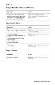
Paper Feed Problems Symptom Action Paper fails to the "CompactFlash/ SmartMedia Service Check" on page 2-8. Paper skews Go to the "Paper Path Service Check" on page 2-11. Go to the "First Print Line Service Check" on page 2-5. • Fails to pick paper • Picks more than one sheet of paper • Picks paper but does not print from a PC. Power Problems Symptom No power in printer Action Go to the "Power Service Check" on page 2-10. Prints from a CompactFlash card. 4102-P01 CompactFlash/SmartMedia Card Problems Symptom...
Paper Feed Problems Symptom Action Paper fails to the "CompactFlash/ SmartMedia Service Check" on page 2-8. Paper skews Go to the "Paper Path Service Check" on page 2-11. Go to the "First Print Line Service Check" on page 2-5. • Fails to pick paper • Picks more than one sheet of paper • Picks paper but does not print from a PC. Power Problems Symptom No power in printer Action Go to the "Power Service Check" on page 2-10. Prints from a CompactFlash card. 4102-P01 CompactFlash/SmartMedia Card Problems Symptom...
Service Manual
Page 20
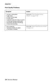
4102-P01 Print Quality Problems Symptom Action • Voids in characters • Light print • Prints off the page • Fuzzy print • Carrier moves but does not print • Printhead drying prematurely • Excessive ink flow (Flooding) • Horizontal banding Go to the "Print Quality Service Check" on page 2-12. • Ink smearing • Vertical streaks on paper • Print lines crowded Go to the "Paper Feed Service Check" on page 2-8. 2-4 Service Manual
4102-P01 Print Quality Problems Symptom Action • Voids in characters • Light print • Prints off the page • Fuzzy print • Carrier moves but does not print • Printhead drying prematurely • Excessive ink flow (Flooding) • Horizontal banding Go to the "Print Quality Service Check" on page 2-12. • Ink smearing • Vertical streaks on paper • Print lines crowded Go to the "Paper Feed Service Check" on page 2-8. 2-4 Service Manual
Service Manual
Page 24
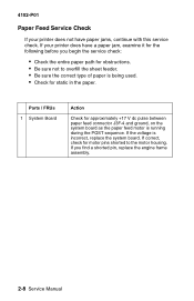
... the sheet feeder. • Be sure the correct type of paper is being used. • Check for static in the paper. If you begin the service check: • Check the entire paper path for approximately +17 V dc pulse between paper feed connector J3F-4 and ground, on the system board as the paper feed motor is incorrect, replace the system board. If your printer does not have a paper jam, examine...
... the sheet feeder. • Be sure the correct type of paper is being used. • Check for static in the paper. If you begin the service check: • Check the entire paper path for approximately +17 V dc pulse between paper feed connector J3F-4 and ground, on the system board as the paper feed motor is incorrect, replace the system board. If your printer does not have a paper jam, examine...
Service Manual
Page 25
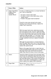
... that fails to the motor housing. If you notice a bind, isolate it by removing one direction only, replace the system board. Diagnostic Information 2-9 If correct, plug in the printer and check the voltage reading of the left side frame. Check for binds in the gear train and paper feed mechanism by rotating the large feed roll by : Assembly System Board • An open...
... that fails to the motor housing. If you notice a bind, isolate it by removing one direction only, replace the system board. Diagnostic Information 2-9 If correct, plug in the printer and check the voltage reading of the left side frame. Check for binds in the gear train and paper feed mechanism by rotating the large feed roll by : Assembly System Board • An open...
Service Manual
Page 26
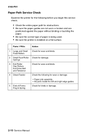
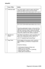
... binding or buckling the paper. • Be sure the correct type of -Forms Flag & Spring • Paper pick assembly • All parts inside the left and right edge guides. Check for wear and binds. Parts / FRUs Action 1 Large and Small Feed Rollers 2 Small Feed Roller Springs 3 Exit Roller Star Rollers Exit Drive Belt and Tensioner 4 Sheet Feeder Check for binds or damage. 2-10 Service Manual
... binding or buckling the paper. • Be sure the correct type of -Forms Flag & Spring • Paper pick assembly • All parts inside the left and right edge guides. Check for wear and binds. Parts / FRUs Action 1 Large and Small Feed Rollers 2 Small Feed Roller Springs 3 Exit Roller Star Rollers Exit Drive Belt and Tensioner 4 Sheet Feeder Check for binds or damage. 2-10 Service Manual
Service Manual
Page 27
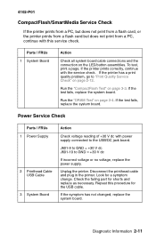
If the printer prints correctly, continue with power supply connected to the USB/DC jack board. If the test fails, replace the system board. If the test fails, replace the system board. Unplug the printer. To test, print a page. If the printer has a print quality problem, go to GND = +30 V dc If incorrect voltage or no voltage, replace the power supply. Repeat this service check. Disconnect the printhead cable and plug in the printer. If the symptom has not changed, replace the...
If the printer prints correctly, continue with power supply connected to the USB/DC jack board. If the test fails, replace the system board. If the test fails, replace the system board. Unplug the printer. To test, print a page. If the printer has a print quality problem, go to GND = +30 V dc If incorrect voltage or no voltage, replace the power supply. Repeat this service check. Disconnect the printhead cable and plug in the printer. If the symptom has not changed, replace the...
Service Manual
Page 28
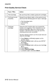
... board and check the following parts for wear or damage: 3 Printhead Cartridge • Print Cartridge Latch • Latch Spring • Carrier Clean the print nozzles when you see SETUP OPTIONS. 3. Press Select. 4. Load plain paper and press Select. 2-12 Service Manual When you clean the print nozzles, a test line prints so you see if the cleaning process was successful. Use the operator panel to run the nozzle test and clean the cartridge. 1. Select Clean/Cartridge. 7. Press the Arrow button until...
... board and check the following parts for wear or damage: 3 Printhead Cartridge • Print Cartridge Latch • Latch Spring • Carrier Clean the print nozzles when you see SETUP OPTIONS. 3. Press Select. 4. Load plain paper and press Select. 2-12 Service Manual When you clean the print nozzles, a test line prints so you see if the cleaning process was successful. Use the operator panel to run the nozzle test and clean the cartridge. 1. Select Clean/Cartridge. 7. Press the Arrow button until...
Service Manual
Page 29
... 4102-P01 Parts / FRUs 4 Printhead Cable Action Your printer feeds a sheet of paper and prints a nozzle test pattern similar to the one shown: 4 Maintenance Station 5 Paper Feed Check the gold-plated contacts, on page 2-6, and then return to this check. You may need to remove the cable from the carrier to clean the contacts. Check the following: • Correct type of the cable that connect to the carrier, for dirt and wear. Use only a clean dry cloth to...
... 4102-P01 Parts / FRUs 4 Printhead Cable Action Your printer feeds a sheet of paper and prints a nozzle test pattern similar to the one shown: 4 Maintenance Station 5 Paper Feed Check the gold-plated contacts, on page 2-6, and then return to this check. You may need to remove the cable from the carrier to clean the contacts. Check the following: • Correct type of the cable that connect to the carrier, for dirt and wear. Use only a clean dry cloth to...
Service Manual
Page 33
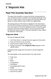
...; Code Level • LCD • Button • CompactFlash • SmartMedia • SmartMedia Write Protect • DRAM • Access Cover Sensor • End-of the pick arm. 4102-P01 3. Press and hold the arrow up button. 3. The tests display on the operator panel. The friction between the pick roll and the paper produces a frictional locking condition. Plug the power supply into the printer. 4. Release the buttons when...
...; Code Level • LCD • Button • CompactFlash • SmartMedia • SmartMedia Write Protect • DRAM • Access Cover Sensor • End-of the pick arm. 4102-P01 3. Press and hold the arrow up button. 3. The tests display on the operator panel. The friction between the pick roll and the paper produces a frictional locking condition. Plug the power supply into the printer. 4. Release the buttons when...

Service Manual
Page 34
... Code Level Displays the current code level on the display. 2. LCD Test To run the Button Test: 1. Button Test To run the LCD Test: 1. The message "Upgrade printer? *=Yes" appears. When reprogramming is "Reprogramming". 6. Select LCD Test from the Diagnostic Menu. Select Button Test from the Diagnostic Menu. Press Print and Return together to upgrade the code: 1. Use the following procedure to stop the test. Press Select. 4. With no buttons pressed, OP (Open) appears several times on the Controller...
... Code Level Displays the current code level on the display. 2. LCD Test To run the Button Test: 1. Button Test To run the LCD Test: 1. The message "Upgrade printer? *=Yes" appears. When reprogramming is "Reprogramming". 6. Select LCD Test from the Diagnostic Menu. Select Button Test from the Diagnostic Menu. Press Print and Return together to upgrade the code: 1. Use the following procedure to stop the test. Press Select. 4. With no buttons pressed, OP (Open) appears several times on the Controller...

Service Manual
Page 36
... DRAM on printer. If no problems are found, the printer returns immediately to verify that each bit in memory can set and read correctly. Raise the access cover. If the transport motor is incorrect, replace the system board. Turn on the System Board. Select DRAM Test from printer. If the voltage is bad, replace the engine frame assembly. If this fails, check all cable connections, sensor switch lever, and carrier...
... DRAM on printer. If no problems are found, the printer returns immediately to verify that each bit in memory can set and read correctly. Raise the access cover. If the transport motor is incorrect, replace the system board. Turn on the System Board. Select DRAM Test from printer. If the voltage is bad, replace the engine frame assembly. If this fails, check all cable connections, sensor switch lever, and carrier...
Service Manual
Page 69
...2-2 CompactFlash/SmartMedia 2-3 Maintenance Station 2-2 Paper Feed 2-3 Paper Feed Button 2-2 Paper Status Light 2-2 Power 2-3 Print Quality 2-4 R Removals 4-2 Access Cover/Second Acess Cover 4-2 Back Cover 4-6 Bottom Cover Assembly 4-6 Button Card 4-7 Engine Board 4-8 Engine Frame Assembly 4-9 Exit Tray 4-10 Ink Carrier Assembly 4-11 Ink Carrier Belt 4-12 LCD Card 4-13 Paper Support Assembly 4-14 Slide Guide 4-15 Top Cover Assembly 4-4 USB/DC Jack Board 4-16 Repair Information Handling ESD-Sensitive Parts 4-1 Resolution and Print Speed 1-4 S Safety Information vi Service Checks Index X-1 4102...
...2-2 CompactFlash/SmartMedia 2-3 Maintenance Station 2-2 Paper Feed 2-3 Paper Feed Button 2-2 Paper Status Light 2-2 Power 2-3 Print Quality 2-4 R Removals 4-2 Access Cover/Second Acess Cover 4-2 Back Cover 4-6 Bottom Cover Assembly 4-6 Button Card 4-7 Engine Board 4-8 Engine Frame Assembly 4-9 Exit Tray 4-10 Ink Carrier Assembly 4-11 Ink Carrier Belt 4-12 LCD Card 4-13 Paper Support Assembly 4-14 Slide Guide 4-15 Top Cover Assembly 4-4 USB/DC Jack Board 4-16 Repair Information Handling ESD-Sensitive Parts 4-1 Resolution and Print Speed 1-4 S Safety Information vi Service Checks Index X-1 4102...


