Service Manual
Page 4
... Voltage Power Supply (model E310 5-16 High Voltage Power Supply (model E312 5-18 Interconnect Board (model E310 5-21 Parts Catalog 6-1 Assembly 1: Covers 6-2 Assembly 2: Frame 6-6 Assembly 3: Fuser 6-10 Assembly 4: Main Drive 6-14 Assembly 5: Paper Feed 6-16 Assembly 6: Electronics (model E310 6-20 Assembly 6: Electronics (model E312 6-24 Assembly 7: Options 6-26 Assembly 8: Miscellaneous 6-27 Index I-1 iv Service Manual
... Voltage Power Supply (model E310 5-16 High Voltage Power Supply (model E312 5-18 Interconnect Board (model E310 5-21 Parts Catalog 6-1 Assembly 1: Covers 6-2 Assembly 2: Frame 6-6 Assembly 3: Fuser 6-10 Assembly 4: Main Drive 6-14 Assembly 5: Paper Feed 6-16 Assembly 6: Electronics (model E310 6-20 Assembly 6: Electronics (model E312 6-24 Assembly 7: Options 6-26 Assembly 8: Miscellaneous 6-27 Index I-1 iv Service Manual

Service Manual
Page 22
4044-XXX Acronyms CSU DRAM EP EPROM ESD FRU HVPS LASER LCD LED LVPS MROM NVRAM OEM PC POST ROM SIMM SRAM UPR USB V ac V dc Customer Setup Dynamic Random Access Memory Electrophotographic Process Erasable, Programmable ... Test Read Only Memory Single In-Line Memory Module Static Random Access Memory Used Parts Return Universal Serial Bus Volts alternating current Volts direct current 1-2 Service Manual
4044-XXX Acronyms CSU DRAM EP EPROM ESD FRU HVPS LASER LCD LED LVPS MROM NVRAM OEM PC POST ROM SIMM SRAM UPR USB V ac V dc Customer Setup Dynamic Random Access Memory Electrophotographic Process Erasable, Programmable ... Test Read Only Memory Single In-Line Memory Module Static Random Access Memory Used Parts Return Universal Serial Bus Volts alternating current Volts direct current 1-2 Service Manual
Service Manual
Page 24
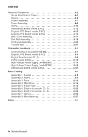
...Go to view the secondary service error code. If this does not correct the problem, replace the engine/LVPS board. 2-2 Service Manual Press and release the operator panel button to diagnose between the ROM SIMM and the controller board. Laser Diode Failure Inspect the ...printhead cable and replace as necessary. Replace the printhead assembly. Blinking Operator Panel LED Software Service Error Code Action Run the Printer...
...Go to view the secondary service error code. If this does not correct the problem, replace the engine/LVPS board. 2-2 Service Manual Press and release the operator panel button to diagnose between the ROM SIMM and the controller board. Laser Diode Failure Inspect the ...printhead cable and replace as necessary. Replace the printhead assembly. Blinking Operator Panel LED Software Service Error Code Action Run the Printer...
Service Manual
Page 26
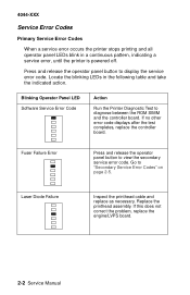
If this does not correct the problem, replace the controller board. 4044-XXX Blinking Operator Panel LED ASIC Register Failure Error Action Replace the controller board ASIC SRAM Failure Error Replace the controller board Flash Memory Failure Error Replace the ROM SIMM w/Flash. Font Checksum Failure Error Replace the ROM SIMM. If this does not correct the problem, replace the controller board. Engine/LVPS Board Communications Failure Error Replace the engine/LVPS board 2-4 Service Manual
If this does not correct the problem, replace the controller board. 4044-XXX Blinking Operator Panel LED ASIC Register Failure Error Action Replace the controller board ASIC SRAM Failure Error Replace the controller board Flash Memory Failure Error Replace the ROM SIMM w/Flash. Font Checksum Failure Error Replace the ROM SIMM. If this does not correct the problem, replace the controller board. Engine/LVPS Board Communications Failure Error Replace the engine/LVPS board 2-4 Service Manual
Service Manual
Page 28
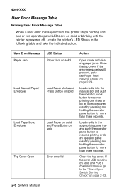
... Jam Load Manual Paper/ Envelope Load Paper/Load Envelope Top Cover Open LED Status Paper Jam on solid Load Paper blinks and Press Button on solid Load Paper on solid and Press Button on solid Error on solid or blinking until the printer is still present, go to the"Paper Feed Service Check..." on page 2-13. 2-6 Service Manual
... Jam Load Manual Paper/ Envelope Load Paper/Load Envelope Top Cover Open LED Status Paper Jam on solid Load Paper blinks and Press Button on solid Load Paper on solid and Press Button on solid Error on solid or blinking until the printer is still present, go to the"Paper Feed Service Check..." on page 2-13. 2-6 Service Manual
Service Manual
Page 30
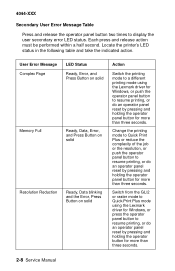
Locate the printer's LED status in the following table and take the indicated action. Switch from the GL/2 or raster mode to Quick Print Plus mode using the Lexmark driver for Windows, or push the operator panel button to resume printing, or do an operator panel reset by pressing and...button two times to resume printing, or do an operator panel reset by pressing and holding the operator button for more than three seconds. 2-8 Service Manual User Error Message Complex Page Memory Full Resolution Reduction LED Status Ready, Error, and Press Button on solid Ready, Data, Error, and Press ...
Locate the printer's LED status in the following table and take the indicated action. Switch from the GL/2 or raster mode to Quick Print Plus mode using the Lexmark driver for Windows, or push the operator panel button to resume printing, or do an operator panel reset by pressing and...button two times to resume printing, or do an operator panel reset by pressing and holding the operator button for more than three seconds. 2-8 Service Manual User Error Message Complex Page Memory Full Resolution Reduction LED Status Ready, Error, and Press Button on solid Ready, Data, Error, and Press ...

Service Manual
Page 32
Fan does not come on . Action Go to the "Cooling Fan Service Check" on page 2-12. Go to "Cover Open Switch Service Check" on page 2-21. Base Printer Symptom Table Symptom Dead Machine (no power) Fan noisy or not working Fuser parts melted Fuser lamp doesn't light Toner not fused to ...Fuser lamp does not come on . Go to the "Cold Fuser Service Check" on page 2-24. Go to the "Operator Panel Service Check" on page 2-17. 2-10 Service Manual Go to "Cold Fuser Service Check" on page 2-23. Go to the "Hot Fuser Service Check" on page 2-12. Fuser lamp never turns off. The paper...
Fan does not come on . Action Go to the "Cooling Fan Service Check" on page 2-12. Go to "Cover Open Switch Service Check" on page 2-21. Base Printer Symptom Table Symptom Dead Machine (no power) Fan noisy or not working Fuser parts melted Fuser lamp doesn't light Toner not fused to ...Fuser lamp does not come on . Go to the "Cold Fuser Service Check" on page 2-24. Go to the "Operator Panel Service Check" on page 2-17. 2-10 Service Manual Go to "Cold Fuser Service Check" on page 2-23. Go to the "Hot Fuser Service Check" on page 2-12. Fuser lamp never turns off. The paper...

Service Manual
Page 34
Cooling Fan Service Check FRU Model E310 Interconnect Board Cooling Fan Action Make sure motor cable is properly seated in location CN408 on the engine board. If the voltage is not present, ... CN3-1 for +24 V dc. If the voltage is present, replace the cooling fan. 2-12 Service Manual This provides the servicer access to the various circuit boards underneath the printer while supplying necessary power to controller board cable disconnected and the printer positioned on its left side. If the voltage is present, replace the cooling fan.
Cooling Fan Service Check FRU Model E310 Interconnect Board Cooling Fan Action Make sure motor cable is properly seated in location CN408 on the engine board. If the voltage is not present, ... CN3-1 for +24 V dc. If the voltage is present, replace the cooling fan. 2-12 Service Manual This provides the servicer access to the various circuit boards underneath the printer while supplying necessary power to controller board cable disconnected and the printer positioned on its left side. If the voltage is present, replace the cooling fan.

Service Manual
Page 36
... after being replaced, install a new fuse and go to the "Engine Board (model E312)" on the LVPS for the high voltage model printer FRU Model E310 & E312 LVPS Fuse 2-14 Service Manual Action Check the fuse on page -9. CN2-3 measures +5 V dc and CN2-4 measures +24 V dc. CN1-4 If any voltages are...replace the HVPS. If the correct voltage is present, check the continuity between the following limits: 100 V ac - 127 V ac for the low voltage model printer 200 V ac - 240 V ac for continuity. CN1-19 CN2-4 - Measure the voltages on page 5-4 and check the engine/ LVPS board output. The...
... after being replaced, install a new fuse and go to the "Engine Board (model E312)" on the LVPS for the high voltage model printer FRU Model E310 & E312 LVPS Fuse 2-14 Service Manual Action Check the fuse on page -9. CN2-3 measures +5 V dc and CN2-4 measures +24 V dc. CN1-4 If any voltages are...replace the HVPS. If the correct voltage is present, check the continuity between the following limits: 100 V ac - 127 V ac for the low voltage model printer 200 V ac - 240 V ac for continuity. CN1-19 CN2-4 - Measure the voltages on page 5-4 and check the engine/ LVPS board output. The...
Service Manual
Page 38
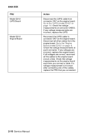
... incorrect, replace the engine board. If a voltage measurement is incorrect after connecting one at a time. Check the voltage measurements at each time you connected. 2-16 Service Manual If all voltages are correct, reconnect all other cables from connector CN7 on the engine board. 4044-XXX FRU Model E312 LVPS Board Model E312...
... incorrect, replace the engine board. If a voltage measurement is incorrect after connecting one at a time. Check the voltage measurements at each time you connected. 2-16 Service Manual If all voltages are correct, reconnect all other cables from connector CN7 on the engine board. 4044-XXX FRU Model E312 LVPS Board Model E312...

Service Manual
Page 40
... the printer off and disconnect the thermistor cable from CN1 on the LVPS board. The voltage rating is stamped on the engine board. 4044-XXX The fuser lamp does light FRU Model 310 Thermistor Model 312 Thermistor Models E310 & E312...printer off and disconnect the thermistor cable from CN10 on the surface of the thermistor between CN10-1 and CN10-3. Replace the thermistor as necessary. The resistance measures approximately 225K ohms when cool. Clean or replace as necessary. Clean or replace as necessary. Measure the resistance of the lamp contacts. 2-18 Service Manual...
... the printer off and disconnect the thermistor cable from CN1 on the LVPS board. The voltage rating is stamped on the engine board. 4044-XXX The fuser lamp does light FRU Model 310 Thermistor Model 312 Thermistor Models E310 & E312...printer off and disconnect the thermistor cable from CN10 on the surface of the thermistor between CN10-1 and CN10-3. Replace the thermistor as necessary. The resistance measures approximately 225K ohms when cool. Clean or replace as necessary. Clean or replace as necessary. Measure the resistance of the lamp contacts. 2-18 Service Manual...

Service Manual
Page 42
... voltage is continuity, go to CN10 on the engine board. If incorrect, replace the thermal fuse. If correct, replace the lamp. 2-20 Service Manual Step 1: Continuity Measure the voltage at connector CN502 on the engine board and measure the voltage between CN10-1 and ground. If the problem persists... Step 2: No Continuity Check the thermal fuse for continuity. 4044-XXX FRU Model E312 Fuser Lamp Lamp Cable Thermistor LVPS Action Turn the printer off and disconnect the fuser lamp wires from CN1o on the LVPS. If there is present, check the fuser lamp cable for continuity. It...
... voltage is continuity, go to CN10 on the engine board. If incorrect, replace the thermal fuse. If correct, replace the lamp. 2-20 Service Manual Step 1: Continuity Measure the voltage at connector CN502 on the engine board and measure the voltage between CN10-1 and ground. If the problem persists... Step 2: No Continuity Check the thermal fuse for continuity. 4044-XXX FRU Model E312 Fuser Lamp Lamp Cable Thermistor LVPS Action Turn the printer off and disconnect the fuser lamp wires from CN1o on the LVPS. If there is present, check the fuser lamp cable for continuity. It...

Service Manual
Page 44
If continuity exists on one or more of the wires, replace the cable. 2-22 Service Manual If these voltages are correct, check the main motor cable for the following voltages: CN2-3 +24 V dc CN2-4 +24 V dc If these voltages are not correct, replace the engine board. If continuity does not exist on each wire, replace the main motor. 4044-XXX FRU Model E312 Engine Board Main Motor Main Motor Cable Action Check the engine board for continuity.
If continuity exists on one or more of the wires, replace the cable. 2-22 Service Manual If these voltages are correct, check the main motor cable for the following voltages: CN2-3 +24 V dc CN2-4 +24 V dc If these voltages are not correct, replace the engine board. If continuity does not exist on each wire, replace the main motor. 4044-XXX FRU Model E312 Engine Board Main Motor Main Motor Cable Action Check the engine board for continuity.

Service Manual
Page 46
... Disconnect the operator panel from the operator panel cable. Paper Feed Service Check Paper Jam error indication during POST FRU Models E310 & E312 Exit Sensor Flag Models E310 & E312 Input Paper Feed Sensor Action If the exit sensor flag... is operating freely and correctly installed. Make sure the flag is not resting within the paper exit sensor during POST, the printer ...operator panel cable. A stuck or incorrectly installed sensor causes this error. 2-24 Service Manual
... Disconnect the operator panel from the operator panel cable. Paper Feed Service Check Paper Jam error indication during POST FRU Models E310 & E312 Exit Sensor Flag Models E310 & E312 Input Paper Feed Sensor Action If the exit sensor flag... is operating freely and correctly installed. Make sure the flag is not resting within the paper exit sensor during POST, the printer ...operator panel cable. A stuck or incorrectly installed sensor causes this error. 2-24 Service Manual

Service Manual
Page 48
Check for the following voltages: CN6-3 +5 V dc CN6-4 Ground If these voltages are not correct, replace the engine board. If correct, replace the input paper feed sensor. 2-26 Service Manual 4044-XXX FRU Model E312 Input Paper Feed Sensor Engine Board Action Make sure the input paper feed sensor is seated on the CN6 connector on the input paper feed sensor. Disconnect the cable and check for a broken or stuck flag on the engine board. Check to make sure the cable is working properly.
Check for the following voltages: CN6-3 +5 V dc CN6-4 Ground If these voltages are not correct, replace the engine board. If correct, replace the input paper feed sensor. 2-26 Service Manual 4044-XXX FRU Model E312 Input Paper Feed Sensor Engine Board Action Make sure the input paper feed sensor is seated on the CN6 connector on the input paper feed sensor. Disconnect the cable and check for a broken or stuck flag on the engine board. Check to make sure the cable is working properly.

Service Manual
Page 50
... cable for the media being printed. A worn transfer roller causes the printer to evenly distribute the toner. Disconnect the printhead cable from the HVPS and measure the signals on the model E312. 2-28 Service Manual If the cable does not measure continuity, replace the cable. If the... the printhead. 4044-XXX Paper "trees", wrinkles, stacks poorly or curls FRU Models E310 & E312 Transfer Roller Action This problem is most likely due to the "High Voltage Power Supply (model E310)" on page 5-16 in the connector locations chapter and check the voltage measurements. Excessive...
... cable for the media being printed. A worn transfer roller causes the printer to evenly distribute the toner. Disconnect the printhead cable from the HVPS and measure the signals on the model E312. 2-28 Service Manual If the cable does not measure continuity, replace the cable. If the... the printhead. 4044-XXX Paper "trees", wrinkles, stacks poorly or curls FRU Models E310 & E312 Transfer Roller Action This problem is most likely due to the "High Voltage Power Supply (model E310)" on page 5-16 in the connector locations chapter and check the voltage measurements. Excessive...

Service Manual
Page 52
... the contacts for correct installation and contamination where contact is made with the toner cartridge and HVPS Board. Clean as necessary. FRU Models E310 & E12 Toner Cartridge Model E310 HVPS Contacts HVPS Board Engine/LVPS Board Model E312 HVPS Contacts HVPS Board Engine Board Action Make sure toner cartridge is more noticeable... a new cartridge. If this does not correct the problem, replace the following FRUs one at a time in the order shown: HVPS Board Engine Board 2-30 Service Manual
... the contacts for correct installation and contamination where contact is made with the toner cartridge and HVPS Board. Clean as necessary. FRU Models E310 & E12 Toner Cartridge Model E310 HVPS Contacts HVPS Board Engine/LVPS Board Model E312 HVPS Contacts HVPS Board Engine Board Action Make sure toner cartridge is more noticeable... a new cartridge. If this does not correct the problem, replace the following FRUs one at a time in the order shown: HVPS Board Engine Board 2-30 Service Manual

Service Manual
Page 54
Inspect the roller and gear. Replace as necessary. 2-32 Service Manual The backup roller of the fuser or gear driving the hot roll may be contaminated or damaged. The supply roller or gear driving the supply ...
Inspect the roller and gear. Replace as necessary. 2-32 Service Manual The backup roller of the fuser or gear driving the hot roll may be contaminated or damaged. The supply roller or gear driving the supply ...
Service Manual
Page 56
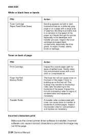
... the paper if toner is building up on the hot roll. Incorrect characters print Make sure the correct printer driver software is primarily due to the backside of the paper. Inspect the toner cartridge and paper feed... backup roller, later transferring to a variation in the speed of the paper as it feeds through the printer especially in the developer and transfer process. Inspect the hot roll and backup roller for signs of spilled ... as necessary. This buildup may not fit the page. 2-34 Service Manual Toner on a page with a soft cloth or compressed air. Banding is installed.
... the paper if toner is building up on the hot roll. Incorrect characters print Make sure the correct printer driver software is primarily due to the backside of the paper. Inspect the toner cartridge and paper feed... backup roller, later transferring to a variation in the speed of the paper as it feeds through the printer especially in the developer and transfer process. Inspect the hot roll and backup roller for signs of spilled ... as necessary. This buildup may not fit the page. 2-34 Service Manual Toner on a page with a soft cloth or compressed air. Banding is installed.

Service Manual
Page 58
4044-XXX 2-36 Service Manual
4044-XXX 2-36 Service Manual


