
Hardware Maintenance Manual
Page 3
...Hard-disk password 24 Supervisor password 24 Power management 25 Screen blank mode 25 Putting your computer to sleep 25 Shutting down the computer 26 Lenovo Y400/Y500 27 Specifications 27 Status indicators 30 Fn key combinations 32 FRU replacement notices 33 Screw notices 33 Removing and replacing an FRU 34 1010...Card slot compartment cover 38 1050 Hard disk drive 39 1060 DIMM 41 1070 PCI Express Mini Card for wireless LAN/WAN 42 1080 Keyboard 44 1090 Keyboard bezel 47 1100 System board 51 1110 LCD unit 55 1120 Fan assembly and Heat Sink assembly 58 1130 CPU 60 1140 Base ...
...Hard-disk password 24 Supervisor password 24 Power management 25 Screen blank mode 25 Putting your computer to sleep 25 Shutting down the computer 26 Lenovo Y400/Y500 27 Specifications 27 Status indicators 30 Fn key combinations 32 FRU replacement notices 33 Screw notices 33 Removing and replacing an FRU 34 1010...Card slot compartment cover 38 1050 Hard disk drive 39 1060 DIMM 41 1070 PCI Express Mini Card for wireless LAN/WAN 42 1080 Keyboard 44 1090 Keyboard bezel 47 1100 System board 51 1110 LCD unit 55 1120 Fan assembly and Heat Sink assembly 58 1130 CPU 60 1140 Base ...
Hardware Maintenance Manual
Page 24
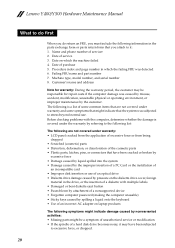
Lenovo Y400/Y500 Hardware Maintenance Manual What to do first When you do return an FRU, you attach to it may be a symptom of unauthorized service or modification. &#... computer password (making the computer unusable) • Sticky keys caused by nonwarranted activities: • Missing parts might indicate damage caused by spilling a liquid onto the keyboard • Use of an incorrect AC adapter on which the failing FRU was caused by misuse, accident, modification, unsuitable physical or operating environment, or improper...
Lenovo Y400/Y500 Hardware Maintenance Manual What to do first When you do return an FRU, you attach to it may be a symptom of unauthorized service or modification. &#... computer password (making the computer unusable) • Sticky keys caused by nonwarranted activities: • Missing parts might indicate damage caused by spilling a liquid onto the keyboard • Use of an incorrect AC adapter on which the failing FRU was caused by misuse, accident, modification, unsuitable physical or operating environment, or improper...
Hardware Maintenance Manual
Page 29
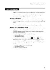
... three power management modes: screen blank, sleep (standby), and hibernation. To put the computer to sleep. Screen blank mode If the time set on the keyboard. 25 Note: Wait until the power indicator light starts blinking (indicating that the computer is in the operating system expires, the LCD backlight turns off...
... three power management modes: screen blank, sleep (standby), and hibernation. To put the computer to sleep. Screen blank mode If the time set on the keyboard. 25 Note: Wait until the power indicator light starts blinking (indicating that the computer is in the operating system expires, the LCD backlight turns off...
Hardware Maintenance Manual
Page 32
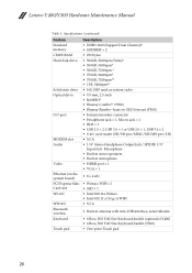
Lenovo Y400/Y500 Hardware Maintenance Manual Table 1. Specifications (continued) Feature Standard memory CMOS RAM Hard disk drive Solid-state drive Optical drive I/O port MODEM slot Audio Video Ethernet (on the system board) PCI Express Mini Card slot WLAN WWAN Bluetooth wireless Keyboard Touch pad Description • DDR3 1600 (Support Dual...; Intel 802.11 a/b/g/n WIFI • N/A • Built-in antenna with min-USB interface, select Models • 6 Row, ISO Full Size Keyboard,backlit (optional) (Y400) • 6 Row, ISO Full Size Keyboard,backlit (Y500) • One-piece Touch pad 28
Lenovo Y400/Y500 Hardware Maintenance Manual Table 1. Specifications (continued) Feature Standard memory CMOS RAM Hard disk drive Solid-state drive Optical drive I/O port MODEM slot Audio Video Ethernet (on the system board) PCI Express Mini Card slot WLAN WWAN Bluetooth wireless Keyboard Touch pad Description • DDR3 1600 (Support Dual...; Intel 802.11 a/b/g/n WIFI • N/A • Built-in antenna with min-USB interface, select Models • 6 Row, ISO Full Size Keyboard,backlit (optional) (Y400) • 6 Row, ISO Full Size Keyboard,backlit (Y500) • One-piece Touch pad 28
Hardware Maintenance Manual
Page 35
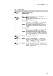
... and 20% of its capacity, or the computer is in uppercase without pressing the Shift key. Blinking amber: (100ms off/3.2s on the keyboard is disabled. d Caps lock e Num lock White: Caps Lock mode is being charged with the remaining power between 20% and 80% of...The remaining power of its capacity. Status indicators Indicator a Power on battery power with the remaining power between 5% and 20% of its capacity. Lenovo Y400/Y500 Table 2. Amber: The computer is operating on b Battery status c Touchpad Meaning White: System is less than 80% of its capacity. To ...
... and 20% of its capacity, or the computer is in uppercase without pressing the Shift key. Blinking amber: (100ms off/3.2s on the keyboard is disabled. d Caps lock e Num lock White: Caps Lock mode is being charged with the remaining power between 20% and 80% of...The remaining power of its capacity. Status indicators Indicator a Power on battery power with the remaining power between 5% and 20% of its capacity. Lenovo Y400/Y500 Table 2. Amber: The computer is operating on b Battery status c Touchpad Meaning White: System is less than 80% of its capacity. To ...
Hardware Maintenance Manual
Page 36
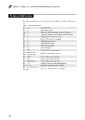
... key. View current Apps. Enable/Disable the scroll lock. Enter sleep mode. Turn on /off the keyboard backlight. 32 Toggle airplane mode on select models): Cancel hotkey. View all Apps. Activate the insert function. Lenovo Y400/Y500 Hardware Maintenance Manual Fn key combinations The following table shows the function of each combination of...
... key. View current Apps. Enable/Disable the scroll lock. Enter sleep mode. Turn on /off the keyboard backlight. 32 Toggle airplane mode on select models): Cancel hotkey. View all Apps. Activate the insert function. Lenovo Y400/Y500 Hardware Maintenance Manual Fn key combinations The following table shows the function of each combination of...

Hardware Maintenance Manual
Page 48
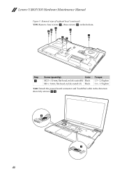
... a . a a a Step a Screw (quantity) M2.5 × 4 mm, flat-head, nylok-coated (2) (Y400) M2.5 × 10 mm, flat-head, nylok-coated (3) (Y500) Color Black Black Torque 1.5 ~ 2.0 kgfcm 44 Lenovo Y400/Y500 Hardware Maintenance Manual 1080 Keyboard For access, remove these FRUs in order: • see "1010 Battery pack" on page 35 • see "1030 Optical drive... • see "1060 DIMM" on page 41 • see "1070 PCI Express Mini Card for wireless LAN/WAN" on page 42 Figure 8. Removal steps of keyboard Y400: Remove two screws a .
... a . a a a Step a Screw (quantity) M2.5 × 4 mm, flat-head, nylok-coated (2) (Y400) M2.5 × 10 mm, flat-head, nylok-coated (3) (Y500) Color Black Black Torque 1.5 ~ 2.0 kgfcm 44 Lenovo Y400/Y500 Hardware Maintenance Manual 1080 Keyboard For access, remove these FRUs in order: • see "1010 Battery pack" on page 35 • see "1030 Optical drive... • see "1060 DIMM" on page 41 • see "1070 PCI Express Mini Card for wireless LAN/WAN" on page 42 Figure 8. Removal steps of keyboard Y400: Remove two screws a .
Hardware Maintenance Manual
Page 49
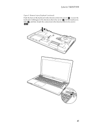
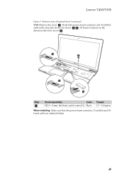
Lift the keyboard a little c, and then detach the connectors in the direction shown by arrow b. Lenovo Y400/Y500 Figure 8. Loosen the keyboard with fingers in the direction shown by arrow a. Removal steps of keyboard (continued) Push the back of the keyboard in the direction shown by arrows d e. a Y500 b 45
Lift the keyboard a little c, and then detach the connectors in the direction shown by arrow b. Lenovo Y400/Y500 Figure 8. Loosen the keyboard with fingers in the direction shown by arrow a. Removal steps of keyboard (continued) Push the back of the keyboard in the direction shown by arrows d e. a Y500 b 45
Hardware Maintenance Manual
Page 50
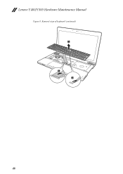
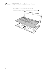
Lenovo Y400/Y500 Hardware Maintenance Manual Figure 8. Removal steps of keyboard (continued) c Y500 e d 46
Lenovo Y400/Y500 Hardware Maintenance Manual Figure 8. Removal steps of keyboard (continued) c Y500 e d 46

Hardware Maintenance Manual
Page 51
Lenovo Y400/Y500 1090 Keyboard bezel For access, remove these FRUs in order: • see "1010 Battery pack" on page 35 • see "1020 Dummy card" on page 36 • ... "1060 DIMM" on page 41 • see "1070 PCI Express Mini Card for wireless LAN/WAN" on page 42 • see "1080 Keyboard" on the bottom. Removal steps of keyboard bezel Y400: Remove three screws a and three screws b on page 44 Figure 9. b b a b a a Step a Screw (quantity) Color M2.5 × 8 mm, flat-head, nylok...
Lenovo Y400/Y500 1090 Keyboard bezel For access, remove these FRUs in order: • see "1010 Battery pack" on page 35 • see "1020 Dummy card" on page 36 • ... "1060 DIMM" on page 41 • see "1070 PCI Express Mini Card for wireless LAN/WAN" on page 42 • see "1080 Keyboard" on the bottom. Removal steps of keyboard bezel Y400: Remove three screws a and three screws b on page 44 Figure 9. b b a b a a Step a Screw (quantity) Color M2.5 × 8 mm, flat-head, nylok...
Hardware Maintenance Manual
Page 52
c Y400 d 48 Lenovo Y400/Y500 Hardware Maintenance Manual Figure 9. b bb a a aa Step a Screw (quantity) Color M2.5 × 10 mm, flat-head, nylok-coated(4) Black M2 × 3 mm, flat-head, nylok-coated (3) Black Torque 1.5 ~ 2.0 kgfcm 1.0 ~ 1.5 kgfcm Y400: Detach the power board connector and TouchPad cable in the direction shown by arrows c d . Removal steps of keyboard bezel (continued) Y500: Remove four screws a , three screws b on the bottom.
c Y400 d 48 Lenovo Y400/Y500 Hardware Maintenance Manual Figure 9. b bb a a aa Step a Screw (quantity) Color M2.5 × 10 mm, flat-head, nylok-coated(4) Black M2 × 3 mm, flat-head, nylok-coated (3) Black Torque 1.5 ~ 2.0 kgfcm 1.0 ~ 1.5 kgfcm Y400: Detach the power board connector and TouchPad cable in the direction shown by arrows c d . Removal steps of keyboard bezel (continued) Y500: Remove four screws a , three screws b on the bottom.
Hardware Maintenance Manual
Page 53
d Y500 c e f Step a Screw (quantity) Color M2.5 × 4 mm, flat-head, nylok-coated (1) Black Torque 1.5 ~ 2.0 kgfcm When installing: Make sure that the power board connector, TouchPad and IO board cable are attached firmly. 49 IO board connector in the direction shown by arrow f . Detach the power board connector and TouchPad cable in the direction shown by arrows d e . Removal steps of keyboard bezel (continued) Y500: Remove the screw c . Lenovo Y400/Y500 Figure 9.
d Y500 c e f Step a Screw (quantity) Color M2.5 × 4 mm, flat-head, nylok-coated (1) Black Torque 1.5 ~ 2.0 kgfcm When installing: Make sure that the power board connector, TouchPad and IO board cable are attached firmly. 49 IO board connector in the direction shown by arrow f . Detach the power board connector and TouchPad cable in the direction shown by arrows d e . Removal steps of keyboard bezel (continued) Y500: Remove the screw c . Lenovo Y400/Y500 Figure 9.
Hardware Maintenance Manual
Page 54
Removal steps of keyboard bezel (continued) Remove the keyboard bezel in the direction shown by arrow g. Y500 g 50 Lenovo Y400/Y500 Hardware Maintenance Manual Figure 9.
Removal steps of keyboard bezel (continued) Remove the keyboard bezel in the direction shown by arrow g. Y500 g 50 Lenovo Y400/Y500 Hardware Maintenance Manual Figure 9.

Hardware Maintenance Manual
Page 55
Lenovo Y400/Y500 1100 System board Important notices for handling the system board: When handling the system board, bear the following in order: • see "1010 Battery pack" ... "1060 DIMM" on page 41 • see "1070 PCI Express Mini Card for wireless LAN/WAN" on page 42 • see "1080 Keyboard" on page 44 • see "1090 Keyboard bezel" on a padded surface such as an ESD mat or conductive corrugated material. For access, remove these FRUs in mind. • Be...
Lenovo Y400/Y500 1100 System board Important notices for handling the system board: When handling the system board, bear the following in order: • see "1010 Battery pack" ... "1060 DIMM" on page 41 • see "1070 PCI Express Mini Card for wireless LAN/WAN" on page 42 • see "1080 Keyboard" on page 44 • see "1090 Keyboard bezel" on a padded surface such as an ESD mat or conductive corrugated material. For access, remove these FRUs in mind. • Be...

Hardware Maintenance Manual
Page 59
Remove screws b . bb Y400 bb a a Step Screw (quantity) b M2.5 × 4 flat-head, nylok-coated (4) Color Torque Black 1.5 ~2.0 kgfcm 55 Lenovo Y400/Y500 1110 LCD unit For access, remove these FRUs in the direction shown by arrows a . Removal steps of LCD unit Y400: Release the antenna cables from ... 39 • see "1060 DIMM" on page 41 • see "1070 PCI Express Mini Card for wireless LAN/WAN" on page 42 • see "1080 Keyboard" on page 44 • see "1090 Keyboard bezel" on page 47 • see "1100 System board" on page 51 Figure 11.
Remove screws b . bb Y400 bb a a Step Screw (quantity) b M2.5 × 4 flat-head, nylok-coated (4) Color Torque Black 1.5 ~2.0 kgfcm 55 Lenovo Y400/Y500 1110 LCD unit For access, remove these FRUs in the direction shown by arrows a . Removal steps of LCD unit Y400: Release the antenna cables from ... 39 • see "1060 DIMM" on page 41 • see "1070 PCI Express Mini Card for wireless LAN/WAN" on page 42 • see "1080 Keyboard" on page 44 • see "1090 Keyboard bezel" on page 47 • see "1100 System board" on page 51 Figure 11.

Hardware Maintenance Manual
Page 62
Lenovo Y400/Y500 Hardware Maintenance Manual 1120 Fan assembly and Heat Sink assembly For access, remove these FRUs in order: • see "1010 Battery pack" on page 35 &#... 39 • see "1060 DIMM" on page 41 • see "1070 PCI Express Mini Card for wireless LAN/WAN" on page 42 • see "1080 Keyboard" on page 44 • see "1090 Keyboard bezel" on page 47 • see "1100 System board" on page 51 58
Lenovo Y400/Y500 Hardware Maintenance Manual 1120 Fan assembly and Heat Sink assembly For access, remove these FRUs in order: • see "1010 Battery pack" on page 35 &#... 39 • see "1060 DIMM" on page 41 • see "1070 PCI Express Mini Card for wireless LAN/WAN" on page 42 • see "1080 Keyboard" on page 44 • see "1090 Keyboard bezel" on page 47 • see "1100 System board" on page 51 58
Hardware Maintenance Manual
Page 64
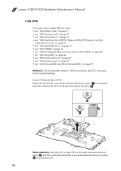
... extremely sensitive. Figure 13. Removal steps of CPU Rotate the head of the screw in the direction shown by arrow a to secure the CPU. 60 Lenovo Y400/Y500 Hardware Maintenance Manual 1130 CPU For access, remove these FRUs in order: • see "1010 Battery pack" on page 35 • see "1020 Dummy... "1060 DIMM" on page 41 • see "1070 PCI Express Mini Card for wireless LAN/WAN" on page 42 • see "1080 Keyboard" on page 44 • see "1090 Keyboard bezel" on page 47 • see "1100 System board" on page 51 • see "1120 Fan assembly and Heat Sink assembly" on...
... extremely sensitive. Figure 13. Removal steps of CPU Rotate the head of the screw in the direction shown by arrow a to secure the CPU. 60 Lenovo Y400/Y500 Hardware Maintenance Manual 1130 CPU For access, remove these FRUs in order: • see "1010 Battery pack" on page 35 • see "1020 Dummy... "1060 DIMM" on page 41 • see "1070 PCI Express Mini Card for wireless LAN/WAN" on page 42 • see "1080 Keyboard" on page 44 • see "1090 Keyboard bezel" on page 47 • see "1100 System board" on page 51 • see "1120 Fan assembly and Heat Sink assembly" on...
Hardware Maintenance Manual
Page 65
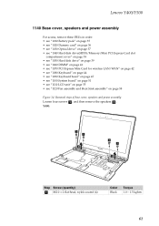
Removal steps of base cover, speakers and power assembly Loosen four screws a , and then remove the speakers b . Lenovo Y400/Y500 1140 Base cover, speakers and power assembly For access, remove these FRUs in order: • see "1010 Battery pack" on page 35 • see "1020 ... "1060 DIMM" on page 41 • see "1070 PCI Express Mini Card for wireless LAN/WAN" on page 42 • see "1080 Keyboard" on page 44 • see "1090 Keyboard bezel" on page 47 • see "1100 System board" on page 51 • see "1110 LCD unit" on page 55 • see...
Removal steps of base cover, speakers and power assembly Loosen four screws a , and then remove the speakers b . Lenovo Y400/Y500 1140 Base cover, speakers and power assembly For access, remove these FRUs in order: • see "1010 Battery pack" on page 35 • see "1020 ... "1060 DIMM" on page 41 • see "1070 PCI Express Mini Card for wireless LAN/WAN" on page 42 • see "1080 Keyboard" on page 44 • see "1090 Keyboard bezel" on page 47 • see "1100 System board" on page 51 • see "1110 LCD unit" on page 55 • see...
Hardware Maintenance Manual
Page 70
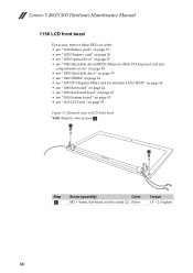
a a Step a Screw (quantity) Color M2 × 4 mm, flat-head, nylok-coated (2) Silver Torque 1.5 ~ 2.0 kgfcm 66 Lenovo Y400/Y500 Hardware Maintenance Manual 1150 LCD front bezel For access, remove these FRUs in order: • see "1010 Battery pack" on page 35 • see "1020 ... "1060 DIMM" on page 41 • see "1070 PCI Express Mini Card for wireless LAN/WAN" on page 42 • see "1080 Keyboard" on page 44 • see "1090 Keyboard bezel" on page 47 • see "1100 System board" on page 51 • see "1110 LCD unit" on page 55 Figure 15...
a a Step a Screw (quantity) Color M2 × 4 mm, flat-head, nylok-coated (2) Silver Torque 1.5 ~ 2.0 kgfcm 66 Lenovo Y400/Y500 Hardware Maintenance Manual 1150 LCD front bezel For access, remove these FRUs in order: • see "1010 Battery pack" on page 35 • see "1020 ... "1060 DIMM" on page 41 • see "1070 PCI Express Mini Card for wireless LAN/WAN" on page 42 • see "1080 Keyboard" on page 44 • see "1090 Keyboard bezel" on page 47 • see "1100 System board" on page 51 • see "1110 LCD unit" on page 55 Figure 15...
Hardware Maintenance Manual
Page 72
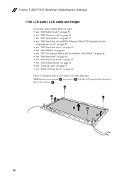
... "1060 DIMM" on page 41 • see "1070 PCI Express Mini Card for wireless LAN/WAN" on page 42 • see "1080 Keyboard" on page 44 • see "1090 Keyboard bezel" on page 47 • see "1100 System board" on page 51 • see "1110 LCD unit" on page 55 • see... "1150 LCD front bezel" on page 66 Figure 16. Lenovo Y400/Y500 Hardware Maintenance Manual 1160 LCD panel, LCD cable and hinges For access, remove...
... "1060 DIMM" on page 41 • see "1070 PCI Express Mini Card for wireless LAN/WAN" on page 42 • see "1080 Keyboard" on page 44 • see "1090 Keyboard bezel" on page 47 • see "1100 System board" on page 51 • see "1110 LCD unit" on page 55 • see... "1150 LCD front bezel" on page 66 Figure 16. Lenovo Y400/Y500 Hardware Maintenance Manual 1160 LCD panel, LCD cable and hinges For access, remove...


