Hardware Maintenance Manual
Page 44
... and press Enter twice. 8. The user hard disk password and the master hard disk password have been removed. Select Hard-disk x password where x is the letter of the Fn+F4 key combination by a ... on the timer, and the user does not do any action to save changes and exit the ThinkPad Setup program. Note: The computer does not accept any key. To put the computer into sleep ... To enter sleep mode, press Fn+F4. Wait a few seconds before taking any operation with the keyboard, the TrackPoint®, the hard disk drive, the parallel connector, or the optical drive within that time...
... and press Enter twice. 8. The user hard disk password and the master hard disk password have been removed. Select Hard-disk x password where x is the letter of the Fn+F4 key combination by a ... on the timer, and the user does not do any action to save changes and exit the ThinkPad Setup program. Note: The computer does not accept any key. To put the computer into sleep ... To enter sleep mode, press Fn+F4. Wait a few seconds before taking any operation with the keyboard, the TrackPoint®, the hard disk drive, the parallel connector, or the optical drive within that time...
Hardware Maintenance Manual
Page 61
...An electronic version of your product with finger print reader and touchpad. - ThinkPad computers contain the following types of CRUs include the ac power adapter, power... request. If you intend on installing the CRU, Lenovo will be required to you might include the memory module, wireless card, keyboard, and palm rest with a replacement part you can... find the manual for your product and are concealed by no more than two screws. You might be included with your product. Once the access panel is removed...
...An electronic version of your product with finger print reader and touchpad. - ThinkPad computers contain the following types of CRUs include the ac power adapter, power... request. If you intend on installing the CRU, Lenovo will be required to you might include the memory module, wireless card, keyboard, and palm rest with a replacement part you can... find the manual for your product and are concealed by no more than two screws. You might be included with your product. Once the access panel is removed...
Hardware Maintenance Manual
Page 78
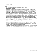
... or hard disk drive connector is detached from the keyboard bezel. 72 Hardware Maintenance Manual Press the keyboard in the direction shown by the arrow 2 until the front edge of the keyboard is attached firmly. 1060 Keyboard For access, remove these FRUs in order: • "1010 Battery... pack" on page 66 • "1030 Memory module slot cover" on page 68 Removal steps of keyboard 1. When installing: Make sure that secure the keyboard. 1 1 Step 1 Screw (...
... or hard disk drive connector is detached from the keyboard bezel. 72 Hardware Maintenance Manual Press the keyboard in the direction shown by the arrow 2 until the front edge of the keyboard is attached firmly. 1060 Keyboard For access, remove these FRUs in order: • "1010 Battery... pack" on page 66 • "1030 Memory module slot cover" on page 68 Removal steps of keyboard 1. When installing: Make sure that secure the keyboard. 1 1 Step 1 Screw (...
Hardware Maintenance Manual
Page 79
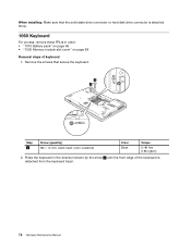
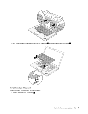
Chapter 10. Removing or replacing a FRU 73 3. Lift the keyboard in the direction shown by the arrow 3 , and then detach the connector 4 . 3 4 Installation steps of keyboard When installing the keyboard, do the following: 1. Attach the keyboard connector 1 .
Chapter 10. Removing or replacing a FRU 73 3. Lift the keyboard in the direction shown by the arrow 3 , and then detach the connector 4 . 3 4 Installation steps of keyboard When installing the keyboard, do the following: 1. Attach the keyboard connector 1 .
Hardware Maintenance Manual
Page 81
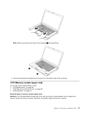
...Memory module (upper slot) For access, remove these FRUs in order: • "1010 Battery pack" on page 66 • "1030 Memory module slot cover" on page 68 • "1060 Keyboard" on page 72 Removal steps of memory module (upper slot) Attention: For ThinkPad W530 models that the front side of the... keyboard b is housed firmly. Chapter 10. Note: Make sure that come with two dummy cards ...
...Memory module (upper slot) For access, remove these FRUs in order: • "1010 Battery pack" on page 66 • "1030 Memory module slot cover" on page 68 • "1060 Keyboard" on page 72 Removal steps of memory module (upper slot) Attention: For ThinkPad W530 models that the front side of the... keyboard b is housed firmly. Chapter 10. Note: Make sure that come with two dummy cards ...
Hardware Maintenance Manual
Page 82
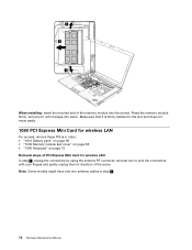
...not move easily. 1080 PCI Express Mini Card for wireless LAN For access, remove these FRUs in order: • "1010 Battery pack" on page 66 • "1030 Memory module slot cover" on page 68 • "1060 Keyboard" on page 72 Removal steps of PCI Express Mini Card for wireless LAN In step 1 , ...unplug the connectors by using the antenna RF connector removal tool or pick the connectors with your fingers and gently unplug them in step...
...not move easily. 1080 PCI Express Mini Card for wireless LAN For access, remove these FRUs in order: • "1010 Battery pack" on page 66 • "1030 Memory module slot cover" on page 68 • "1060 Keyboard" on page 72 Removal steps of PCI Express Mini Card for wireless LAN In step 1 , ...unplug the connectors by using the antenna RF connector removal tool or pick the connectors with your fingers and gently unplug them in step...
Hardware Maintenance Manual
Page 84
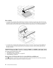
..., 1090 PCI Express Mini Card for wireless WAN (full-size WWAN card) In step 1 , unplug the connectors by using the antenna RF connector removal tool or pick the connectors with a wireless LAN card that has three antenna connectors, plug the gray cable (MAIN) into the main connector, the...drive For access, remove these FRUs in direction of the arrow. 78 Hardware Maintenance Manual When installing: • In models with your fingers and gently unplug them in order: • "1010 Battery pack" on page 66 • "1030 Memory module slot cover" on page 68 • "1060 Keyboard" on the card...
..., 1090 PCI Express Mini Card for wireless WAN (full-size WWAN card) In step 1 , unplug the connectors by using the antenna RF connector removal tool or pick the connectors with a wireless LAN card that has three antenna connectors, plug the gray cable (MAIN) into the main connector, the...drive For access, remove these FRUs in direction of the arrow. 78 Hardware Maintenance Manual When installing: • In models with your fingers and gently unplug them in order: • "1010 Battery pack" on page 66 • "1030 Memory module slot cover" on page 68 • "1060 Keyboard" on the card...
Hardware Maintenance Manual
Page 89
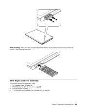
1 2 When installing: Make sure that the ExpressCard blank bezel or ExpressCard is correctly oriented as shown in the following illustration. 1110 Keyboard bezel assembly For access, remove these FRUs in order: • "1010 Battery pack" on page 66 • "1030 Memory module slot cover" on page 68 • "1060 Keyboard" on page 72 • "1100 ExpressCard blank bezel or ExpressCard" on page 82 Chapter 10. Removing or replacing a FRU 83
1 2 When installing: Make sure that the ExpressCard blank bezel or ExpressCard is correctly oriented as shown in the following illustration. 1110 Keyboard bezel assembly For access, remove these FRUs in order: • "1010 Battery pack" on page 66 • "1030 Memory module slot cover" on page 68 • "1060 Keyboard" on page 72 • "1100 ExpressCard blank bezel or ExpressCard" on page 82 Chapter 10. Removing or replacing a FRU 83
Hardware Maintenance Manual
Page 90
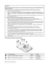
...perform the initial color calibration, or provide instructions to the customer to the new keyboard bezel assembly. 3. Click OK to run this utility. 7. Removal steps of their image, you replace the keyboard bezel assembly, back up in step 1, to replace the LCD panel even if... replacements: 1. When the initial calibration completes, a dialog box is not defective, and only the keyboard bezel assembly needs a replacement: 1. After you use the color sensor for ThinkPad W530 models with the color sensor, follow the instructions on how to exit the Sensor Replacement Utility program...
...perform the initial color calibration, or provide instructions to the customer to the new keyboard bezel assembly. 3. Click OK to run this utility. 7. Removal steps of their image, you replace the keyboard bezel assembly, back up in step 1, to replace the LCD panel even if... replacements: 1. When the initial calibration completes, a dialog box is not defective, and only the keyboard bezel assembly needs a replacement: 1. After you use the color sensor for ThinkPad W530 models with the color sensor, follow the instructions on how to exit the Sensor Replacement Utility program...
Hardware Maintenance Manual
Page 92
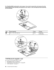
For ThinkPad W530 models with a color sensor, if you need to remove the color sensor from the failing keyboard bezel assembly and install the color sensor to the new keyboard bezel assembly, do the following: 3 3 4 1 2 Step 3 Screw (quantity) M2 × L7 mm, bind-head, (2) 1 Color Silver Torque 0.181 Nm (1.85 kgfcm) 4 4 3 2 1120 Bluetooth daughter card For access, remove these FRUs in order: • "1010 Battery pack" on page 66 • "1030 Memory module slot cover" on page 68 • "1060 Keyboard" on page 72 86 Hardware Maintenance Manual
For ThinkPad W530 models with a color sensor, if you need to remove the color sensor from the failing keyboard bezel assembly and install the color sensor to the new keyboard bezel assembly, do the following: 3 3 4 1 2 Step 3 Screw (quantity) M2 × L7 mm, bind-head, (2) 1 Color Silver Torque 0.181 Nm (1.85 kgfcm) 4 4 3 2 1120 Bluetooth daughter card For access, remove these FRUs in order: • "1010 Battery pack" on page 66 • "1030 Memory module slot cover" on page 68 • "1060 Keyboard" on page 72 86 Hardware Maintenance Manual
Hardware Maintenance Manual
Page 93
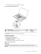
...Make sure that the connector is attached firmly. 1130 Backup battery For access, remove these FRUs in order: • "1010 Battery pack" on page 66 • "1030 Memory module slot cover" on page 68 • "1060 Keyboard" on page 72 • "1100 ExpressCard blank bezel or ExpressCard" on ...page 82 Removal steps of backup battery DANGER Use only the authorized battery specified for your computer. Any other battery could ignite...
...Make sure that the connector is attached firmly. 1130 Backup battery For access, remove these FRUs in order: • "1010 Battery pack" on page 66 • "1030 Memory module slot cover" on page 68 • "1060 Keyboard" on page 72 • "1100 ExpressCard blank bezel or ExpressCard" on ...page 82 Removal steps of backup battery DANGER Use only the authorized battery specified for your computer. Any other battery could ignite...
Hardware Maintenance Manual
Page 94
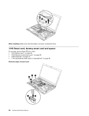
When installing: Make sure that the battery connector is attached firmly. 1140 Smart card, dummy smart card and spacer For access, remove these FRUs in order: • "1010 Battery pack" on page 66 • "1030 Memory module slot cover" on page 68 • "1060 Keyboard" on page 72 • "1100 ExpressCard blank bezel or ExpressCard" on page 82 Removal steps of smart card 33 3 4 1 2 88 Hardware Maintenance Manual
When installing: Make sure that the battery connector is attached firmly. 1140 Smart card, dummy smart card and spacer For access, remove these FRUs in order: • "1010 Battery pack" on page 66 • "1030 Memory module slot cover" on page 68 • "1060 Keyboard" on page 72 • "1100 ExpressCard blank bezel or ExpressCard" on page 82 Removal steps of smart card 33 3 4 1 2 88 Hardware Maintenance Manual
Hardware Maintenance Manual
Page 95
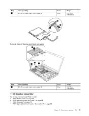
Step 3 Screw (quantity) M2 × 3 mm, wafer-head, nylon-coated (3) Color Silver Torque 0.181 Nm (1.85 kgfcm) 5 6 5 Removal steps of dummy smart card and spacer 3 1 1 1 2 Step 1 Screw (quantity) M2 × 3 mm, wafer-head, nylon-coated (3) Color Silver 1150 Speaker assembly For access, remove these FRUs in order: • "1010 Battery pack" on page 66 • "1030 Memory module slot cover" on page 68 • "1060 Keyboard" on page 72 • "1100 ExpressCard blank bezel or ExpressCard" on page 82 Torque 0.181 Nm (1.85 kgfcm) Chapter 10. Removing or replacing a FRU 89
Step 3 Screw (quantity) M2 × 3 mm, wafer-head, nylon-coated (3) Color Silver Torque 0.181 Nm (1.85 kgfcm) 5 6 5 Removal steps of dummy smart card and spacer 3 1 1 1 2 Step 1 Screw (quantity) M2 × 3 mm, wafer-head, nylon-coated (3) Color Silver 1150 Speaker assembly For access, remove these FRUs in order: • "1010 Battery pack" on page 66 • "1030 Memory module slot cover" on page 68 • "1060 Keyboard" on page 72 • "1100 ExpressCard blank bezel or ExpressCard" on page 82 Torque 0.181 Nm (1.85 kgfcm) Chapter 10. Removing or replacing a FRU 89

Hardware Maintenance Manual
Page 97
Removing or replacing a FRU 91 Notes: • Loosen the screws 3a to 3d in ascending alphabetic order as illustrated, but do not remove them. • Some models do not have screws 4 . • "1060 Keyboard" on page 72 • "1100 ExpressCard blank bezel or ExpressCard" on page 82 • "1150 Speaker assembly" on page 89 Removal steps of thermal fan assembly 1 When installing: Make sure that the connector is attached firmly. For those models, skip step 4 . 4 2 4 3a 3d 4 3c 3b Chapter 10.
Removing or replacing a FRU 91 Notes: • Loosen the screws 3a to 3d in ascending alphabetic order as illustrated, but do not remove them. • Some models do not have screws 4 . • "1060 Keyboard" on page 72 • "1100 ExpressCard blank bezel or ExpressCard" on page 82 • "1150 Speaker assembly" on page 89 Removal steps of thermal fan assembly 1 When installing: Make sure that the connector is attached firmly. For those models, skip step 4 . 4 2 4 3a 3d 4 3c 3b Chapter 10.
Hardware Maintenance Manual
Page 99
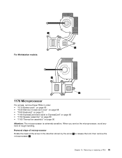
... Microprocessor For access, remove these FRUs in the direction shown by the arrow 1 to release the lock; When you service the microprocessor, avoid any kind of the screw in order: • "1010 Battery pack" on page 66 • "1030 Memory module slot cover" on page 68 • "1060 Keyboard" on page 72...
... Microprocessor For access, remove these FRUs in the direction shown by the arrow 1 to release the lock; When you service the microprocessor, avoid any kind of the screw in order: • "1010 Battery pack" on page 66 • "1030 Memory module slot cover" on page 68 • "1060 Keyboard" on page 72...
Hardware Maintenance Manual
Page 100
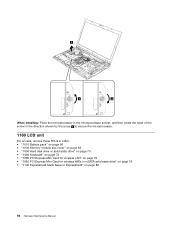
... socket, and then rotate the head of the screw in the direction shown by the arrow a to secure the microprocessor. 1180 LCD unit For access, remove these FRUs in order: • "1010 Battery pack" on page 66 • "1030 Memory module slot cover" on page 68 • "1050 Hard disk drive... or solid state drive" on page 70 • "1060 Keyboard" on page 72 • "1080 PCI Express Mini Card for wireless LAN" on page 76 • "1090 PCI Express Mini Card for wireless WAN or...
... socket, and then rotate the head of the screw in the direction shown by the arrow a to secure the microprocessor. 1180 LCD unit For access, remove these FRUs in order: • "1010 Battery pack" on page 66 • "1030 Memory module slot cover" on page 68 • "1050 Hard disk drive... or solid state drive" on page 70 • "1060 Keyboard" on page 72 • "1080 PCI Express Mini Card for wireless LAN" on page 76 • "1090 PCI Express Mini Card for wireless WAN or...
Hardware Maintenance Manual
Page 103
... For access, remove these FRUs in order: • "1010 Battery pack" on page 66 • "1020 Serial Ultrabay Enhanced device or blank bezel" on page 67 • "1030 Memory module slot cover" on page 68 • "1050 Hard disk drive or solid state drive" on page 70 • "1060 Keyboard" on page... 88 • "1150 Speaker assembly" on page 89 • "1160 Thermal fan assembly" on page 90 • "1180 LCD unit" on page 94 Chapter 10. Removing or replacing a FRU 97
... For access, remove these FRUs in order: • "1010 Battery pack" on page 66 • "1020 Serial Ultrabay Enhanced device or blank bezel" on page 67 • "1030 Memory module slot cover" on page 68 • "1050 Hard disk drive or solid state drive" on page 70 • "1060 Keyboard" on page... 88 • "1150 Speaker assembly" on page 89 • "1160 Thermal fan assembly" on page 90 • "1180 LCD unit" on page 94 Chapter 10. Removing or replacing a FRU 97
Hardware Maintenance Manual
Page 106
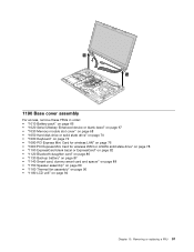
... • "1040 Memory module (bottom slot)" on page 69 • "1050 Hard disk drive or solid state drive" on page 70 • "1060 Keyboard" on page 97 Removal steps of I /O sub card" on the magnesium structure frame. The ac power connector is attached firmly. 1210 System board assembly and magnesium structure frame...
... • "1040 Memory module (bottom slot)" on page 69 • "1050 Hard disk drive or solid state drive" on page 70 • "1060 Keyboard" on page 97 Removal steps of I /O sub card" on the magnesium structure frame. The ac power connector is attached firmly. 1210 System board assembly and magnesium structure frame...
Hardware Maintenance Manual
Page 112
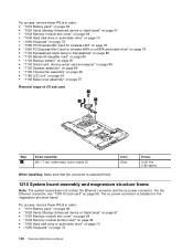
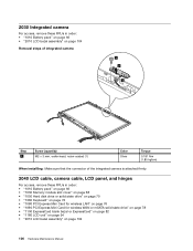
...order: • "1010 Battery pack" on page 66 • "2010 LCD bezel assembly" on page 104 Removal steps of integrated camera 1 3 2 Step 1 Screw (quantity) M2 × 3 mm, wafer-head, nylon... of the integrated camera is attached firmly. 2040 LCD cable, camera cable, LCD panel, and hinges For access, remove these FRUs in order: • "1010 Battery pack" on page 66 • "1030 Memory module slot cover... on page 68 • "1050 Hard disk drive or solid state drive" on page 70 • "1060 Keyboard" on page 72 • "1080 PCI Express Mini Card for wireless LAN" on page 76 • "1090 ...
...order: • "1010 Battery pack" on page 66 • "2010 LCD bezel assembly" on page 104 Removal steps of integrated camera 1 3 2 Step 1 Screw (quantity) M2 × 3 mm, wafer-head, nylon... of the integrated camera is attached firmly. 2040 LCD cable, camera cable, LCD panel, and hinges For access, remove these FRUs in order: • "1010 Battery pack" on page 66 • "1030 Memory module slot cover... on page 68 • "1050 Hard disk drive or solid state drive" on page 70 • "1060 Keyboard" on page 72 • "1080 PCI Express Mini Card for wireless LAN" on page 76 • "1090 ...
Hardware Maintenance Manual
Page 116
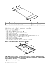
... page 66 • "1030 Memory module slot cover" on page 68 • "1050 Hard disk drive or solid state drive" on page 70 • "1060 Keyboard" on page 72 • "1080 PCI Express Mini Card for wireless LAN" on page 76 • "1090 PCI Express Mini Card for wireless WAN or... unit" on page 94 • "2010 LCD bezel assembly" on page 104 • "2040 LCD cable, camera cable, LCD panel, and hinges" on page 106 Removal steps of antenna kit and LCD rear cover assembly 3 1 3 2 2 3 3 2 2 1 Cable routing: When you route the cables, make sure that they are not subject to be...
... page 66 • "1030 Memory module slot cover" on page 68 • "1050 Hard disk drive or solid state drive" on page 70 • "1060 Keyboard" on page 72 • "1080 PCI Express Mini Card for wireless LAN" on page 76 • "1090 PCI Express Mini Card for wireless WAN or... unit" on page 94 • "2010 LCD bezel assembly" on page 104 • "2040 LCD cable, camera cable, LCD panel, and hinges" on page 106 Removal steps of antenna kit and LCD rear cover assembly 3 1 3 2 2 3 3 2 2 1 Cable routing: When you route the cables, make sure that they are not subject to be...

