(English) BIOS Setup using Windows Management Instrumentation Deployment Guide
Page 34
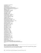
Replace "AlwaysOnUSB" with the name of the setting to display the... IEEE1394Access = Enable SerialPortAccess = Enable ParallelPortAccess = Enable CardBusSlotAccess = Enable ExpressCardAccess = Enable PCIExpressSlotAccess = Enable PrimaryVideo = Internal BootDisplayDevice = LCD TimerWakeWithBattery = Disable UltrabayAccess = Enable MemoryCardSlotAccess = Enable SmartCardSlotAccess = Enable IntegratedCameraAccess = Enable MicrophoneAccess = Enable BootMode = Quick StartupOptionKeys = Enable...as templates to be queried. 26 Lenovo BIOS Setup using Windows Management Instrumentation Deployment Guide
Replace "AlwaysOnUSB" with the name of the setting to display the... IEEE1394Access = Enable SerialPortAccess = Enable ParallelPortAccess = Enable CardBusSlotAccess = Enable ExpressCardAccess = Enable PCIExpressSlotAccess = Enable PrimaryVideo = Internal BootDisplayDevice = LCD TimerWakeWithBattery = Disable UltrabayAccess = Enable MemoryCardSlotAccess = Enable SmartCardSlotAccess = Enable IntegratedCameraAccess = Enable MicrophoneAccess = Enable BootMode = Quick StartupOptionKeys = Enable...as templates to be queried. 26 Lenovo BIOS Setup using Windows Management Instrumentation Deployment Guide

Hardware Maintenance Manual
Page 3
... management 44 Screen blank mode 44 Sleep (standby) mode 44 Hibernation mode 45 Symptom-to do first 29 Checkout guide 30 System supporting the Lenovo ThinkVantage Toolbox program and the PC-Doctor for CTO, CMV, and GAV products 27 Chapter 3. General checkout . . . . . 29 ...Numeric error codes 46 Error messages 50 Beep symptoms 51 No-beep symptoms 52 LCD-related symptoms 52 Intermittent problems 52 Undetermined problems 53 Chapter 5. Removing and replacing a FRU 69 Before servicing ThinkPad T510, T510i, and W510 70 1010 Battery pack 70 1020 Serial Ultrabay Enhanced device...
... management 44 Screen blank mode 44 Sleep (standby) mode 44 Hibernation mode 45 Symptom-to do first 29 Checkout guide 30 System supporting the Lenovo ThinkVantage Toolbox program and the PC-Doctor for CTO, CMV, and GAV products 27 Chapter 3. General checkout . . . . . 29 ...Numeric error codes 46 Error messages 50 Beep symptoms 51 No-beep symptoms 52 LCD-related symptoms 52 Intermittent problems 52 Undetermined problems 53 Chapter 5. Removing and replacing a FRU 69 Before servicing ThinkPad T510, T510i, and W510 70 1010 Battery pack 70 1020 Serial Ultrabay Enhanced device...

Hardware Maintenance Manual
Page 58
...or software errors. The hard-disk password prompt appears. FRU or action, in loop mode at least 10 times. 52 ThinkPad T510, T510i, and W510 Hardware Maintenance Manual The presence of a small number of dots that are servicing has two or less... ThinkPad Notebooks purchased on 1 January, 2008 or later. • Lenovo will be replaced. Intermittent problems Intermittent system hang problems can cause viewing concerns.If the LCD you are missing, discolored, or always lighted is connected tightly and correctly. 2. Make sure that any replacement LCD will have nothing to all LCD ...
...or software errors. The hard-disk password prompt appears. FRU or action, in loop mode at least 10 times. 52 ThinkPad T510, T510i, and W510 Hardware Maintenance Manual The presence of a small number of dots that are servicing has two or less... ThinkPad Notebooks purchased on 1 January, 2008 or later. • Lenovo will be replaced. Intermittent problems Intermittent system hang problems can cause viewing concerns.If the LCD you are missing, discolored, or always lighted is connected tightly and correctly. 2. Make sure that any replacement LCD will have nothing to all LCD ...

Hardware Maintenance Manual
Page 59
.... 6. Rerun the test to the docking station or the port replicator c. Non-ThinkPad devices b. Battery pack e. Optical disk or diskette in the internal drive i. PC Cards 4. If the problem remains, replace the following devices: a. Verify that the power supply being used at the time ... the adapter or device that no error is operating correctly. (See "Power system checkout" on the computer. 5. Turn on page 37.) 1. LCD assembly Chapter 4. DIMM h. System board b. Printer, mouse, and other external devices d. If any error is not operating, follow these procedures to...
.... 6. Rerun the test to the docking station or the port replicator c. Non-ThinkPad devices b. Battery pack e. Optical disk or diskette in the internal drive i. PC Cards 4. If the problem remains, replace the following devices: a. Verify that the power supply being used at the time ... the adapter or device that no error is operating correctly. (See "Power system checkout" on the computer. 5. Turn on page 37.) 1. LCD assembly Chapter 4. DIMM h. System board b. Printer, mouse, and other external devices d. If any error is not operating, follow these procedures to...

Hardware Maintenance Manual
Page 103
Removing and replacing a FRU 97 Removal steps of CPU Rotate the head of the screw in the direction shown by arrow a to secure the CPU. 1170 LCD unit For access, remove these FRUs in order: • "1010 Battery pack" on page 70 • "1030 DIMM slot cover" on page 73 • "1050 ...
Removing and replacing a FRU 97 Removal steps of CPU Rotate the head of the screw in the direction shown by arrow a to secure the CPU. 1170 LCD unit For access, remove these FRUs in order: • "1010 Battery pack" on page 70 • "1030 DIMM slot cover" on page 73 • "1050 ...

Hardware Maintenance Manual
Page 105
Removing and replacing a FRU 99 Tension could cause the cables to be damaged by the cable guides, or a wire to any tension. Table 32. Removal steps of LCD unit (continued) 7 8 7 6 4 4 5 5 4 Step 7 Screw (quantity) M2 × 4 mm, wafer-head, nylon-coated (2) Color Black Torque 0.181 Nm (1.85 kgfcm) ...When installing: • Make sure that you attach the LCD connector firmly. • Make sure that you route the cables firmly and tape up in the proper positions as shown in this figure. • ...
Removing and replacing a FRU 99 Tension could cause the cables to be damaged by the cable guides, or a wire to any tension. Table 32. Removal steps of LCD unit (continued) 7 8 7 6 4 4 5 5 4 Step 7 Screw (quantity) M2 × 4 mm, wafer-head, nylon-coated (2) Color Black Torque 0.181 Nm (1.85 kgfcm) ...When installing: • Make sure that you attach the LCD connector firmly. • Make sure that you route the cables firmly and tape up in the proper positions as shown in this figure. • ...

Hardware Maintenance Manual
Page 109
...or Smart Card dummy spacer" on page 89 • "1140 Speaker assembly" on page 92 • "1150 Thermal module" on page 94 • "1170 LCD unit" on page 97 • "1180 Base cover assembly" on page 102 for these FRUs in order: • "1010 Battery pack" on page 70 •...) 1200 System board assembly and magnesium structure frame Note: The system board does not contain neither the Ethernet port nor the modem port. Removing and replacing a FRU 103 See "1190 I /O sub card 1 2 11 Step 1 Screw (quantity) M2 × 7 mm, flat-head, nylon-coated (3) When installing: Make sure that the ...
...or Smart Card dummy spacer" on page 89 • "1140 Speaker assembly" on page 92 • "1150 Thermal module" on page 94 • "1170 LCD unit" on page 97 • "1180 Base cover assembly" on page 102 for these FRUs in order: • "1010 Battery pack" on page 70 •...) 1200 System board assembly and magnesium structure frame Note: The system board does not contain neither the Ethernet port nor the modem port. Removing and replacing a FRU 103 See "1190 I /O sub card 1 2 11 Step 1 Screw (quantity) M2 × 7 mm, flat-head, nylon-coated (3) When installing: Make sure that the ...

Hardware Maintenance Manual
Page 110
... subject the accelerometer to as much as 6,000 G's of G-forces. The procedure is running. 104 ThinkPad T510, T510i, and W510 Hardware Maintenance Manual If the system supports PC-Doctor for DOS, after replacing the system board, run PC-Doctor for handling the system board: When handling the system board, bear...89 • "1140 Speaker assembly" on page 92 • "1150 Thermal module" on page 94 • "1160 CPU" on page 96 • "1170 LCD unit" on page 97 • "1180 Base cover assembly" on page 100 • "1190 I/O sub card" on page 102 Important notices for RAID setting: ...
... subject the accelerometer to as much as 6,000 G's of G-forces. The procedure is running. 104 ThinkPad T510, T510i, and W510 Hardware Maintenance Manual If the system supports PC-Doctor for DOS, after replacing the system board, run PC-Doctor for handling the system board: When handling the system board, bear...89 • "1140 Speaker assembly" on page 92 • "1150 Thermal module" on page 94 • "1160 CPU" on page 96 • "1170 LCD unit" on page 97 • "1180 Base cover assembly" on page 100 • "1190 I/O sub card" on page 102 Important notices for RAID setting: ...

Hardware Maintenance Manual
Page 113
a b c 2010 LCD bezel assembly For access, remove this figure. Removal steps of system board and magnesium structure frame (continued) When installing: When you are servicing, the number of thermal rubbers are different. Depend on the models you replace the system board, attach thermal rubbers as ... new FRU package and apply them to the new system board. Removing and replacing a FRU 107 Table 36. Removal steps of them in this FRU: • "1010 Battery pack" on the old system board, and find duplicates of LCD bezel assembly 1 1 1 Step 1 Screw cap Screw (quantity) M2.5 ...
a b c 2010 LCD bezel assembly For access, remove this figure. Removal steps of system board and magnesium structure frame (continued) When installing: When you are servicing, the number of thermal rubbers are different. Depend on the models you replace the system board, attach thermal rubbers as ... new FRU package and apply them to the new system board. Removing and replacing a FRU 107 Table 36. Removal steps of them in this FRU: • "1010 Battery pack" on the old system board, and find duplicates of LCD bezel assembly 1 1 1 Step 1 Screw cap Screw (quantity) M2.5 ...

Hardware Maintenance Manual
Page 115
Removing and replacing a FRU 109 2030 Integrated camera For access, remove these FRUs in order: • "1010 Battery pack" on page 70 • "2010 LCD bezel assembly" on page 84 Chapter 9. Removal steps of integrated camera 1 3 2 Step 1 Screw (quantity) M2 × 3 mm, wafer-head, nylon-coated ...(1) Color Silver Torque 0.181 Nm (1.85 kgfcm) When installing: Make sure that the connector of the integrated camera is attached firmly. 2040 LCD cable, camera cable, LCD panel, and hinges For access, remove these FRUs in order: • "1010 Battery pack" on page 70 • "1030 DIMM ...
Removing and replacing a FRU 109 2030 Integrated camera For access, remove these FRUs in order: • "1010 Battery pack" on page 70 • "2010 LCD bezel assembly" on page 84 Chapter 9. Removal steps of integrated camera 1 3 2 Step 1 Screw (quantity) M2 × 3 mm, wafer-head, nylon-coated ...(1) Color Silver Torque 0.181 Nm (1.85 kgfcm) When installing: Make sure that the connector of the integrated camera is attached firmly. 2040 LCD cable, camera cable, LCD panel, and hinges For access, remove these FRUs in order: • "1010 Battery pack" on page 70 • "1030 DIMM ...

Hardware Maintenance Manual
Page 117
Chapter 9. Table 40. Removal steps of LCD cable, camera cable, LCD panel, and hinges (continued) 3 4 5 5 5 6 7 8 When installing: Make sure that the LCD cable connector is attached firmly. Removing and replacing a FRU 111
Chapter 9. Table 40. Removal steps of LCD cable, camera cable, LCD panel, and hinges (continued) 3 4 5 5 5 6 7 8 When installing: Make sure that the LCD cable connector is attached firmly. Removing and replacing a FRU 111
Hardware Maintenance Manual
Page 119
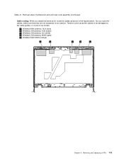
... LAN antenna, AUX (black) c : Wireless LAN antenna, 3rd (white) d : Wireless LAN antenna, MAIN (gray) e : Wireless WAN MAIN (orange) a b c d e Chapter 9. Removal steps of antenna kit and LCD rear cover assembly (continued) Cable routing: When you route the cables, make sure that they are not subjected to be damaged by the cable guides..., or a wire to any tension. As you install the antenna kit, route the cables as shown in the figures below. Removing and replacing a FRU 113 Tension could cause the cables to be broken. Table 41.
... LAN antenna, AUX (black) c : Wireless LAN antenna, 3rd (white) d : Wireless LAN antenna, MAIN (gray) e : Wireless WAN MAIN (orange) a b c d e Chapter 9. Removal steps of antenna kit and LCD rear cover assembly (continued) Cable routing: When you route the cables, make sure that they are not subjected to be damaged by the cable guides..., or a wire to any tension. As you install the antenna kit, route the cables as shown in the figures below. Removing and replacing a FRU 113 Tension could cause the cables to be broken. Table 41.

Hardware Maintenance Manual
Page 125
...Optional-service CRUs. ThinkPad computers contain the following lists of Self-service CRUs is not a CRU. See your Lenovo Limited Warranty documentation for your responsibility; Chapter 11. A single asterisk (*) means that ship with OP are available as xxU (where U is replaced by the CRU.... Installation of the service parts. • "Overall" on page 120 • "LCD FRUs" on page 169...
...Optional-service CRUs. ThinkPad computers contain the following lists of Self-service CRUs is not a CRU. See your Lenovo Limited Warranty documentation for your responsibility; Chapter 11. A single asterisk (*) means that ship with OP are available as xxU (where U is replaced by the CRU.... Installation of the service parts. • "Overall" on page 120 • "LCD FRUs" on page 169...


