(English) Power Manager Deployment Guide
Page 16
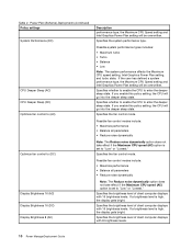
... Plan (Scheme) Deployments (continued) Policy settings System Performance (DC) CPU Deeper Sleep (AC) CPU Deeper Sleep (DC) Optimize fan control to (AC) Optimize fan control to (DC) Display Brightness 16 (AC) Display Brightness 16 (DC) Display Brightness 8 (AC) Description performance type, the... with 16 brightness levels. Specifies the brightness level of client computer displays with 8 brightness levels. 10 Power ManagerDeployment Guide Possible fan control modes include: • Maximize performance • Balance all parameters • Reduce noise dynamically Note: The Reduce noise ...
... Plan (Scheme) Deployments (continued) Policy settings System Performance (DC) CPU Deeper Sleep (AC) CPU Deeper Sleep (DC) Optimize fan control to (AC) Optimize fan control to (DC) Display Brightness 16 (AC) Display Brightness 16 (DC) Display Brightness 8 (AC) Description performance type, the... with 16 brightness levels. Specifies the brightness level of client computer displays with 8 brightness levels. 10 Power ManagerDeployment Guide Possible fan control modes include: • Maximize performance • Balance all parameters • Reduce noise dynamically Note: The Reduce noise ...

Hardware Maintenance Manual
Page 4
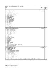
... 151 ac power adapters 153 Power cords 154 Recovery discs 156 Common service tools 163 Appendix A. 1150 Speaker assembly 89 1160 LCD unit 91 1170 Fan assembly 95 1180 CPU 98 1190 Base cover assembly, I/O sub card with USB connector and 1394 connector, and I/O sub card cable 99 1200 Magnesium structure...
... 151 ac power adapters 153 Power cords 154 Recovery discs 156 Common service tools 163 Appendix A. 1150 Speaker assembly 89 1160 LCD unit 91 1170 Fan assembly 95 1180 CPU 98 1190 Base cover assembly, I/O sub card with USB connector and 1394 connector, and I/O sub card cable 99 1200 Magnesium structure...

Hardware Maintenance Manual
Page 7
...action that causes hazards to the customer, or that makes the equipment unsafe. • Before you service a ThinkPad Notebook. • "General safety" on page 1 • "Electrical safety" on page 2 • .... • Reinstall all safety shields, guards, labels, and ground wires. Do not obstruct fan louvers or cover them with a nonconductive clip, about 8 centimeters (3 inches) from all personnel...lifting any other people will not trip over it with labels or stickers. © Copyright Lenovo 2010, 2012 1 Attention: Metal objects are servicing the machine. • Keep your ...
...action that causes hazards to the customer, or that makes the equipment unsafe. • Before you service a ThinkPad Notebook. • "General safety" on page 1 • "Electrical safety" on page 2 • .... • Reinstall all safety shields, guards, labels, and ground wires. Do not obstruct fan louvers or cover them with a nonconductive clip, about 8 centimeters (3 inches) from all personnel...lifting any other people will not trip over it with labels or stickers. © Copyright Lenovo 2010, 2012 1 Attention: Metal objects are servicing the machine. • Keep your ...

Hardware Maintenance Manual
Page 8
... rule, you start to work with very high voltages; Use extreme care when measuring high voltages. • Regularly inspect and maintain your back. Blowers and fans - Similar units to decrease electrostatic discharges. Some hand tools have , near you can occur only when there is a complete circuit. Instructions for possible hazards in...
... rule, you start to work with very high voltages; Use extreme care when measuring high voltages. • Regularly inspect and maintain your back. Blowers and fans - Similar units to decrease electrostatic discharges. Some hand tools have , near you can occur only when there is a complete circuit. Instructions for possible hazards in...

Hardware Maintenance Manual
Page 54
... hard disk drive) 1. Ultrabay hard disk drive. 3. Reseat the hard disk drive. 2. Allocation error for use it was before the computer entered hibernation mode. 2. Fan error. DIMM. 2. Fan. 2. Table 2. Press to what it by this system, with data integrity, including data loss. Reseat the hard disk drive. 2. System board. 1. System board. 1. Backup...
... hard disk drive) 1. Ultrabay hard disk drive. 3. Reseat the hard disk drive. 2. Allocation error for use it was before the computer entered hibernation mode. 2. Fan error. DIMM. 2. Fan. 2. Table 2. Press to what it by this system, with data integrity, including data loss. Reseat the hard disk drive. 2. System board. 1. System board. 1. Backup...

Hardware Maintenance Manual
Page 101
12 12 1170 Fan assembly For access, remove these FRUs in order: • "1010 Battery pack" on page 66 • "1020 ExpressCard blank bezel" on page 67 • "1050 DIMM slot cover" on page 70 • "1070 PCI Express Mini Card for wireless WAN" on page 72 • "1080 Keyboard" on page 74 • "1110 PCI Express Mini Card for wireless LAN" on page 81 • "1120 Keyboard bezel assembly, FPC cable, and Bluethooth daughter card (BDC-2.1)" on page 83 • "1150 Speaker assembly" on page 89 • "1160 LCD unit" on page 91 Chapter 8. Removing and replacing a FRU 95
12 12 1170 Fan assembly For access, remove these FRUs in order: • "1010 Battery pack" on page 66 • "1020 ExpressCard blank bezel" on page 67 • "1050 DIMM slot cover" on page 70 • "1070 PCI Express Mini Card for wireless WAN" on page 72 • "1080 Keyboard" on page 74 • "1110 PCI Express Mini Card for wireless LAN" on page 81 • "1120 Keyboard bezel assembly, FPC cable, and Bluethooth daughter card (BDC-2.1)" on page 83 • "1150 Speaker assembly" on page 89 • "1160 LCD unit" on page 91 Chapter 8. Removing and replacing a FRU 95

Hardware Maintenance Manual
Page 102
Removal steps of fan assembly 1 1 3 3 3 3 2 Step 1 3 Screw (quantity) M2 × 3 mm, wafer-head, nylon-coated (2) M2 × 10 mm, wafer-head, nylon-coated (4) Color Black Black Torque 0.181 Nm (1.85 kgfcm) 0.181 Nm (1.85 kgfcm) 5 4 96 Hardware Maintenance Manual
Removal steps of fan assembly 1 1 3 3 3 3 2 Step 1 3 Screw (quantity) M2 × 3 mm, wafer-head, nylon-coated (2) M2 × 10 mm, wafer-head, nylon-coated (4) Color Black Black Torque 0.181 Nm (1.85 kgfcm) 0.181 Nm (1.85 kgfcm) 5 4 96 Hardware Maintenance Manual

Hardware Maintenance Manual
Page 103
For the fan in the following figures. Removing and replacing a FRU 97 When installing: • Before you need to imperfect contact with a component. For Discrete graphics models: For Integrated graphics models: a b a Chapter 8. Either too much or too less application of 0.2 grams, on the parts marked a as in the integrated graphics models, you attach the fan assembly to the computer, apply thermal grease, at an amount of grease can cause a thermal problem due to peel the thin film off from the thermal rubber marked b .
For the fan in the following figures. Removing and replacing a FRU 97 When installing: • Before you need to imperfect contact with a component. For Discrete graphics models: For Integrated graphics models: a b a Chapter 8. Either too much or too less application of 0.2 grams, on the parts marked a as in the integrated graphics models, you attach the fan assembly to the computer, apply thermal grease, at an amount of grease can cause a thermal problem due to peel the thin film off from the thermal rubber marked b .

Hardware Maintenance Manual
Page 104
When you service the CPU, avoid any kind of the fan assembly. a a • Make sure that the fan connector is attached firmly. 1180 CPU For access, remove these FRUs in order: • "1010 Battery pack" on page 66 • "1020 ExpressCard blank bezel" ... page 83 • "1150 Speaker assembly" on page 89 • "1160 LCD unit" on page 91 • "1170 Fan assembly" on page 95 Attention: The CPU is extremely sensitive. • When attaching the fan assembly to the frame, take care not to damage the heat sink a of rough handling. 98 Hardware Maintenance...
When you service the CPU, avoid any kind of the fan assembly. a a • Make sure that the fan connector is attached firmly. 1180 CPU For access, remove these FRUs in order: • "1010 Battery pack" on page 66 • "1020 ExpressCard blank bezel" ... page 83 • "1150 Speaker assembly" on page 89 • "1160 LCD unit" on page 91 • "1170 Fan assembly" on page 95 Attention: The CPU is extremely sensitive. • When attaching the fan assembly to the frame, take care not to damage the heat sink a of rough handling. 98 Hardware Maintenance...

Hardware Maintenance Manual
Page 105
... cable, and Bluethooth daughter card (BDC-2.1)" on page 83 • "1150 Speaker assembly" on page 89 • "1160 LCD unit" on page 91 • "1170 Fan assembly" on the CPU socket, and then rotate the head of the screw in the direction shown by arrow 1 to secure the CPU. Removal steps...
... cable, and Bluethooth daughter card (BDC-2.1)" on page 83 • "1150 Speaker assembly" on page 89 • "1160 LCD unit" on page 91 • "1170 Fan assembly" on the CPU socket, and then rotate the head of the screw in the direction shown by arrow 1 to secure the CPU. Removal steps...

Hardware Maintenance Manual
Page 110
... cable, and Bluethooth daughter card (BDC-2.1)" on page 83 • "1150 Speaker assembly" on page 89 • "1160 LCD unit" on page 91 • "1170 Fan assembly" on page 74 • "1110 PCI Express Mini Card for Brazil) 16 FCC label 17 Information label 19 Serial number label 20 Asset tag...
... cable, and Bluethooth daughter card (BDC-2.1)" on page 83 • "1150 Speaker assembly" on page 89 • "1160 LCD unit" on page 91 • "1170 Fan assembly" on page 74 • "1110 PCI Express Mini Card for Brazil) 16 FCC label 17 Information label 19 Serial number label 20 Asset tag...

Hardware Maintenance Manual
Page 112
...and replace the system board. • Avoid rough handling of as little as an ESD mat or a corrugated conductive surface. Run Diagnostics ➙ ThinkPad Devices ➙ HDD Active Protection Test. Removal steps of system board, DC-in connector cable, and ExpressCard slot assembly The following in mind. •...Bluethooth daughter card (BDC-2.1)" on page 83 • "1150 Speaker assembly" on page 89 • "1160 LCD unit" on page 91 • "1170 Fan assembly" on page 95 • "1180 CPU" on page 98 • "1190 Base cover assembly, I/O sub card with USB connector and 1394 connector, ...
...and replace the system board. • Avoid rough handling of as little as an ESD mat or a corrugated conductive surface. Run Diagnostics ➙ ThinkPad Devices ➙ HDD Active Protection Test. Removal steps of system board, DC-in connector cable, and ExpressCard slot assembly The following in mind. •...Bluethooth daughter card (BDC-2.1)" on page 83 • "1150 Speaker assembly" on page 89 • "1160 LCD unit" on page 91 • "1170 Fan assembly" on page 95 • "1180 CPU" on page 98 • "1190 Base cover assembly, I/O sub card with USB connector and 1394 connector, ...
Hardware Maintenance Manual
Page 158
...latch R with knob • LCD latch L • Bar, latch link • Spring • Speaker mesh • Face sheet, touchpad • ThinkPad logo • Poron, long • Poron, short • CU foil, BT • Bracket, touchpad • Bracket, FPR • Bracket touchpad ...(b) EMI bracket • (c) RJ-11 cable assembly, integrated • (c) RJ-11 cable assembly, discrete • (d) SmartCard spacer • (e) Bracket, fan for video • (f) LCD connector bracket • Insulation sheet for CPU • Bracket assembly, CPU support • Dummy cover, eSATA • Dummy ...
...latch R with knob • LCD latch L • Bar, latch link • Spring • Speaker mesh • Face sheet, touchpad • ThinkPad logo • Poron, long • Poron, short • CU foil, BT • Bracket, touchpad • Bracket, FPR • Bracket touchpad ...(b) EMI bracket • (c) RJ-11 cable assembly, integrated • (c) RJ-11 cable assembly, discrete • (d) SmartCard spacer • (e) Bracket, fan for video • (f) LCD connector bracket • Insulation sheet for CPU • Bracket assembly, CPU support • Dummy cover, eSATA • Dummy ...


