
Hardware Maintenance Manual
Page 38
...Hardware Maintenance Manual Speaker Interactive Tests ➙ Internal Speaker Note: Once Audio test is done, the no sound is running. Remove any physical shock to start the diagnostic program. Using cursor keys, select HDD diagnostic program. Diagnostics ➙ Other Devices ...the operating system. Press enter. 5. Diagnostics ➙ Diskette Drives 2. To run Diagnostics ➙ ThinkPad Devices ➙ HDD Active Protection Test. Diagnostics ➙ Systemboard ➙ Keyboard 2. To diagnose the drive from the diskette drive, and then turn on the computer. 3. ...
...Hardware Maintenance Manual Speaker Interactive Tests ➙ Internal Speaker Note: Once Audio test is done, the no sound is running. Remove any physical shock to start the diagnostic program. Using cursor keys, select HDD diagnostic program. Diagnostics ➙ Other Devices ...the operating system. Press enter. 5. Diagnostics ➙ Diskette Drives 2. To run Diagnostics ➙ ThinkPad Devices ➙ HDD Active Protection Test. Diagnostics ➙ Systemboard ➙ Keyboard 2. To diagnose the drive from the diskette drive, and then turn on the computer. 3. ...
Hardware Maintenance Manual
Page 83
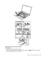
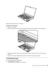
Chapter 8. 3 4 5 3 7 6 7 6 8 Installation of the keyboard bezel as shown in this figure. Attach the cables to the system board firmly. 2. Removing and replacing a FRU 77 Attach the palm rest so that the two small projections of the palm rest a firmly fit into the guide holes of palm rest assembly with cables When installing: 1.
Chapter 8. 3 4 5 3 7 6 7 6 8 Installation of the keyboard bezel as shown in this figure. Attach the cables to the system board firmly. 2. Removing and replacing a FRU 77 Attach the palm rest so that the two small projections of the palm rest a firmly fit into the guide holes of palm rest assembly with cables When installing: 1.
Hardware Maintenance Manual
Page 89
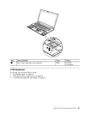
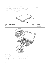
Removing and replacing a FRU 83 2 2 3 Step 2 Screw (quantity) M2 × 3 mm, wafer-head, nylon-coated (2) 1160 Keyboard For access, remove these FRUs in order: • "1010 Battery pack" on page 61 • "1030 Optical drive or travel cover" on page 64 • "1110 Palm rest assembly with cables" on page 76 Color Black Torque 0.181 Nm (1.85 kgfcm) Chapter 8.
Removing and replacing a FRU 83 2 2 3 Step 2 Screw (quantity) M2 × 3 mm, wafer-head, nylon-coated (2) 1160 Keyboard For access, remove these FRUs in order: • "1010 Battery pack" on page 61 • "1030 Optical drive or travel cover" on page 64 • "1110 Palm rest assembly with cables" on page 76 Color Black Torque 0.181 Nm (1.85 kgfcm) Chapter 8.
Hardware Maintenance Manual
Page 90
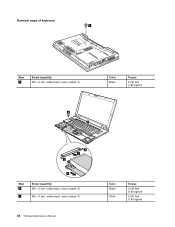
Removal steps of keyboard 1 Step 1 Screw (quantity) M2 × 5 mm, wafer-head, nylon-coated (1) Color Black Torque 0.181 Nm (1.85 kgfcm) 6 7 2 4 2 3 5 Step 6 7 Screw (quantity) M2 × 3 mm, wafer-head, nylon-coated (1) M2 × 2 mm, wafer-head, nylon-coated (1) 84 Hardware Maintenance Manual Color Black Silver Torque 0.181 Nm (1.85 kgfcm) 0.181 Nm (1.85 kgfcm)
Removal steps of keyboard 1 Step 1 Screw (quantity) M2 × 5 mm, wafer-head, nylon-coated (1) Color Black Torque 0.181 Nm (1.85 kgfcm) 6 7 2 4 2 3 5 Step 6 7 Screw (quantity) M2 × 3 mm, wafer-head, nylon-coated (1) M2 × 2 mm, wafer-head, nylon-coated (1) 84 Hardware Maintenance Manual Color Black Silver Torque 0.181 Nm (1.85 kgfcm) 0.181 Nm (1.85 kgfcm)
Hardware Maintenance Manual
Page 91
... tightening the screws from the bottom side of the keyboard 1. Gently press the keys with your palms and slightly slide the keyboard toward you until it snaps into position. 4. Removing and replacing a FRU 85 8 When installing the keyboard, do as shown in order: • "1010 Battery pack"... on page 61 • "1030 Optical drive or travel cover" on page 64 Chapter 8. Attach the keyboard so that the keyboard edge is under the frame as follows: Installation of the computer. 1170 Keyboard bezel For access, remove these FRUs in the following figure. 3. Attach the connectors. 2.
... tightening the screws from the bottom side of the keyboard 1. Gently press the keys with your palms and slightly slide the keyboard toward you until it snaps into position. 4. Removing and replacing a FRU 85 8 When installing the keyboard, do as shown in order: • "1010 Battery pack"... on page 61 • "1030 Optical drive or travel cover" on page 64 Chapter 8. Attach the keyboard so that the keyboard edge is under the frame as follows: Installation of the computer. 1170 Keyboard bezel For access, remove these FRUs in the following figure. 3. Attach the connectors. 2.

Hardware Maintenance Manual
Page 92
... page 76 • "1120 PCI Express Mini Card for wireless LAN" on page 78 • "1160 Keyboard" on page 83 Removal steps of keyboard bezel Note: Steps 2a and 3a are only for ThinkPad SL510 and L510. For ThinkPad SL410 and L410, skip steps 2a to 3a . 3 3 1 2 2 2a 2a 2 1 3a 3 Step 1 2 2a 3 3a Screw (quantity) M2...
... page 76 • "1120 PCI Express Mini Card for wireless LAN" on page 78 • "1160 Keyboard" on page 83 Removal steps of keyboard bezel Note: Steps 2a and 3a are only for ThinkPad SL510 and L510. For ThinkPad SL410 and L410, skip steps 2a to 3a . 3 3 1 2 2 2a 2a 2 1 3a 3 Step 1 2 2a 3 3a Screw (quantity) M2...
Hardware Maintenance Manual
Page 94
... rest assembly with cables" on page 76 • "1120 PCI Express Mini Card for wireless LAN" on page 78 • "1160 Keyboard" on page 83 • "1170 Keyboard bezel" on page 85 Removal steps of LCD unit 1 Step 1 Screw (quantity) M2.5 × 6.5 mm, wafter-head, nylon-coated (2) 1 Color Black Torque 0.392 Nm (4 kgfcm...
... rest assembly with cables" on page 76 • "1120 PCI Express Mini Card for wireless LAN" on page 78 • "1160 Keyboard" on page 83 • "1170 Keyboard bezel" on page 85 Removal steps of LCD unit 1 Step 1 Screw (quantity) M2.5 × 6.5 mm, wafter-head, nylon-coated (2) 1 Color Black Torque 0.392 Nm (4 kgfcm...
Hardware Maintenance Manual
Page 97
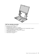
Removing and replacing a FRU 91 6 6 1190 Top shielding assembly For access, remove these FRUs in order: • "1010 Battery pack" on page 61 • "1030 Optical drive or travel cover" on page 64 • "1100 Wireless WAN slot cover and PCI Express Mini Card for wireless WAN" on page 74 • "1110 Palm rest assembly with cables" on page 76 • "1120 PCI Express Mini Card for wireless LAN" on page 78 • "1160 Keyboard" on page 83 • "1170 Keyboard bezel" on page 85 • "1180 LCD unit" on page 87 Chapter 8.
Removing and replacing a FRU 91 6 6 1190 Top shielding assembly For access, remove these FRUs in order: • "1010 Battery pack" on page 61 • "1030 Optical drive or travel cover" on page 64 • "1100 Wireless WAN slot cover and PCI Express Mini Card for wireless WAN" on page 74 • "1110 Palm rest assembly with cables" on page 76 • "1120 PCI Express Mini Card for wireless LAN" on page 78 • "1160 Keyboard" on page 83 • "1170 Keyboard bezel" on page 85 • "1180 LCD unit" on page 87 Chapter 8.
Hardware Maintenance Manual
Page 104
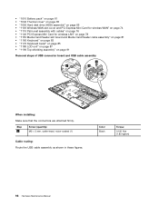
... slot board and Media Card Reader cable assembly" on page 81 • "1160 Keyboard" on page 83 • "1170 Keyboard bezel" on page 85 • "1180 LCD unit" on page 87 • "1190 Top shielding assembly" on page 91 Removal steps of USB connector board and USB cable assembly 2 1 4 3 When installing: Make sure...
... slot board and Media Card Reader cable assembly" on page 81 • "1160 Keyboard" on page 83 • "1170 Keyboard bezel" on page 85 • "1180 LCD unit" on page 87 • "1190 Top shielding assembly" on page 91 Removal steps of USB connector board and USB cable assembly 2 1 4 3 When installing: Make sure...

Hardware Maintenance Manual
Page 105
... and L510: For ThinkPad SL410 and L410: 1220 DC-in cable and base cover For access, remove these FRUs in order: • "1010 Battery pack" on page 61 • "1020 ExpressCard blank bezel and Media Card blank bezel" on page 63 • "... wireless LAN" on page 78 • "1150 Media Card Reader slot board and Media Card Reader cable assembly" on page 81 • "1160 Keyboard" on page 83 • "1170 Keyboard bezel" on page 85 • "1180 LCD unit" on page 87 • "1190 Top shielding assembly" on page 91 • "1200 System...
... and L510: For ThinkPad SL410 and L410: 1220 DC-in cable and base cover For access, remove these FRUs in order: • "1010 Battery pack" on page 61 • "1020 ExpressCard blank bezel and Media Card blank bezel" on page 63 • "... wireless LAN" on page 78 • "1150 Media Card Reader slot board and Media Card Reader cable assembly" on page 81 • "1160 Keyboard" on page 83 • "1170 Keyboard bezel" on page 85 • "1180 LCD unit" on page 87 • "1190 Top shielding assembly" on page 91 • "1200 System...
Hardware Maintenance Manual
Page 109
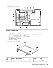
For ThinkPad SL410 and L410: 12 11 10 1 2 3 4 5 6 7 9 8 2010 LCD front bezel For access, remove these FRUs in order: • "1010 Battery pack" on page 61 • "1100 Wireless WAN slot cover and PCI Express Mini Card for wireless WAN" ..." on page 76 • "1120 PCI Express Mini Card for wireless LAN" on page 78 • "1160 Keyboard" on page 83 • "1170 Keyboard bezel" on page 85 • "1180 LCD unit" on page 87 Removal steps of LCD front bezel 1 1 1 1 Step 1 Screw cap Screw (quantity) M2 × 5 mm, wafer-head, nylon-coated...
For ThinkPad SL410 and L410: 12 11 10 1 2 3 4 5 6 7 9 8 2010 LCD front bezel For access, remove these FRUs in order: • "1010 Battery pack" on page 61 • "1100 Wireless WAN slot cover and PCI Express Mini Card for wireless WAN" ..." on page 76 • "1120 PCI Express Mini Card for wireless LAN" on page 78 • "1160 Keyboard" on page 83 • "1170 Keyboard bezel" on page 85 • "1180 LCD unit" on page 87 Removal steps of LCD front bezel 1 1 1 1 Step 1 Screw cap Screw (quantity) M2 × 5 mm, wafer-head, nylon-coated...
Hardware Maintenance Manual
Page 110
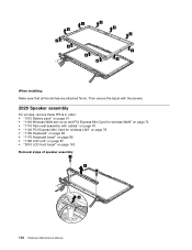
2 2 2 2 2 2 2 2 2 2 2 When installing: Make sure that all the latches are attached firmly. Then secure the bezel with the screws. 2020 Speaker assembly For access, remove these FRUs in order: • "1010 Battery pack" on page 61 • "1100 Wireless WAN slot cover and PCI Express Mini Card for wireless WAN" ...74 • "1110 Palm rest assembly with cables" on page 76 • "1120 PCI Express Mini Card for wireless LAN" on page 78 • "1160 Keyboard" on page 83 • "1170 Keyboard bezel" on page 85 • "1180 LCD unit" on page 87 • "2010 LCD front bezel" on page 103...
2 2 2 2 2 2 2 2 2 2 2 When installing: Make sure that all the latches are attached firmly. Then secure the bezel with the screws. 2020 Speaker assembly For access, remove these FRUs in order: • "1010 Battery pack" on page 61 • "1100 Wireless WAN slot cover and PCI Express Mini Card for wireless WAN" ...74 • "1110 Palm rest assembly with cables" on page 76 • "1120 PCI Express Mini Card for wireless LAN" on page 78 • "1160 Keyboard" on page 83 • "1170 Keyboard bezel" on page 85 • "1180 LCD unit" on page 87 • "2010 LCD front bezel" on page 103...
Hardware Maintenance Manual
Page 111
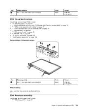
..."1110 Palm rest assembly with cables" on page 76 • "1120 PCI Express Mini Card for wireless LAN" on page 78 • "1160 Keyboard" on page 83 • "1170 Keyboard bezel" on page 85 • "1180 LCD unit" on page 87 • "2010 LCD front bezel" on page 103 • "2020 ...Speaker assembly" on page 104 Removal steps of integrated camera 1 2 1 3 Step 1 Screw (quantity) M2 × 3 mm, wafer-head, nylon-coated (2) When installing: Make sure ...
..."1110 Palm rest assembly with cables" on page 76 • "1120 PCI Express Mini Card for wireless LAN" on page 78 • "1160 Keyboard" on page 83 • "1170 Keyboard bezel" on page 85 • "1180 LCD unit" on page 87 • "2010 LCD front bezel" on page 103 • "2020 ...Speaker assembly" on page 104 Removal steps of integrated camera 1 2 1 3 Step 1 Screw (quantity) M2 × 3 mm, wafer-head, nylon-coated (2) When installing: Make sure ...

Hardware Maintenance Manual
Page 112
..."1110 Palm rest assembly with cables" on page 76 • "1120 PCI Express Mini Card for wireless LAN" on page 78 • "1160 Keyboard" on page 83 • "1170 Keyboard bezel" on page 85 • "1180 LCD unit" on page 87 • "2010 LCD front bezel" on page 103 • "2020... Speaker assembly" on page 104 • "2030 Integrated camera" on page 105 Removal steps of antenna assembly Release the antenna cables from the cable guides of the LCD rear cover assembly and from the hinges. For ThinkPad SL510 and L510: 1 1 1 1 1 1 When installing: Route the cables as shown in ...
..."1110 Palm rest assembly with cables" on page 76 • "1120 PCI Express Mini Card for wireless LAN" on page 78 • "1160 Keyboard" on page 83 • "1170 Keyboard bezel" on page 85 • "1180 LCD unit" on page 87 • "2010 LCD front bezel" on page 103 • "2020... Speaker assembly" on page 104 • "2030 Integrated camera" on page 105 Removal steps of antenna assembly Release the antenna cables from the cable guides of the LCD rear cover assembly and from the hinges. For ThinkPad SL510 and L510: 1 1 1 1 1 1 When installing: Route the cables as shown in ...

Hardware Maintenance Manual
Page 114
... • "1170 Keyboard bezel" on page 85 • "1180 LCD unit" on page 87 • "2010 LCD front bezel" on page 103 • "2020 Speaker assembly" on page 104 • "2030 Integrated camera" on page 105 • "2040 Antenna assembly" on page 105 Removal steps of hinges, ...LCD panel, LCD cable, and LCD rear cover assembly For ThinkPad SL510 and L510: 1 1 1 1 Step 1 Screw (quantity) M2 × 5 mm, wafer-head, nylon-coated (4) For ThinkPad SL410 and L410: 1 Color Black Torque 0.181 Nm (1.85 kgfcm) 1...
... • "1170 Keyboard bezel" on page 85 • "1180 LCD unit" on page 87 • "2010 LCD front bezel" on page 103 • "2020 Speaker assembly" on page 104 • "2030 Integrated camera" on page 105 • "2040 Antenna assembly" on page 105 Removal steps of hinges, ...LCD panel, LCD cable, and LCD rear cover assembly For ThinkPad SL510 and L510: 1 1 1 1 Step 1 Screw (quantity) M2 × 5 mm, wafer-head, nylon-coated (4) For ThinkPad SL410 and L410: 1 Color Black Torque 0.181 Nm (1.85 kgfcm) 1...
Hardware Maintenance Manual
Page 121
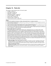
...(customer replaceable unit) is an Optional-service CRU. Once the access panel is removed, the specific CRU is required: (1) return instructions, a prepaid shipping label, and a container will ship... and others are installing the CRU, Lenovo will be used for all models ending in the publications that is your receipt of your responsibility; ThinkPad computers contain the following lists of the...An N in the CRU ID column. Where you may include the memory module, wireless card, keyboard, and palm rest with your product and are held by a single asterisk (*) or two asterisks...
...(customer replaceable unit) is an Optional-service CRU. Once the access panel is removed, the specific CRU is required: (1) return instructions, a prepaid shipping label, and a container will ship... and others are installing the CRU, Lenovo will be used for all models ending in the publications that is your receipt of your responsibility; ThinkPad computers contain the following lists of the...An N in the CRU ID column. Where you may include the memory module, wireless card, keyboard, and palm rest with your product and are held by a single asterisk (*) or two asterisks...

