Hardware Maintenance Manual
Page 4
1170 Keyboard 83 1180 Keyboard bezel 85 1190 LCD unit 87 2010 Top shielding assembly 90 2020 System board assembly 92 2030 USB connector board and USB cable assembly 98 2040 DC-in cable and base cover 99 2050 LCD front bezel 102 2060 Speaker assembly 103 2070 Integrated ...
1170 Keyboard 83 1180 Keyboard bezel 85 1190 LCD unit 87 2010 Top shielding assembly 90 2020 System board assembly 92 2030 USB connector board and USB cable assembly 98 2040 DC-in cable and base cover 99 2050 LCD front bezel 102 2060 Speaker assembly 103 2070 Integrated ...
Hardware Maintenance Manual
Page 9
.... 9. Checklist: 1. Disconnect the power cord. 3. A third-wire ground connector in charge between the external ground pin and the frame ground. b. Remove the cover. 6. Check for any obvious non-ThinkPad alterations. Chapter 1. Power off the computer. Consider these conditions and the safety...determine whether there are present, you must not be the type specified in identifying potentially unsafe conditions. If any non-ThinkPad alterations. 7. Use good judgment as metal filings, contamination, water or other liquids, or signs of every service task....
.... 9. Checklist: 1. Disconnect the power cord. 3. A third-wire ground connector in charge between the external ground pin and the frame ground. b. Remove the cover. 6. Check for any obvious non-ThinkPad alterations. Chapter 1. Power off the computer. Consider these conditions and the safety...determine whether there are present, you must not be the type specified in identifying potentially unsafe conditions. If any non-ThinkPad alterations. 7. Use good judgment as metal filings, contamination, water or other liquids, or signs of every service task....
Hardware Maintenance Manual
Page 10
...; Japanese • Korean • Spanish • Traditional Chinese DANGER DANGER 4 Hardware Maintenance Manual When working on a double-insulated or battery-operated system, use coax or connector-outside shells on ac-operated computers.
...; Japanese • Korean • Spanish • Traditional Chinese DANGER DANGER 4 Hardware Maintenance Manual When working on a double-insulated or battery-operated system, use coax or connector-outside shells on ac-operated computers.
Hardware Maintenance Manual
Page 35
... • Scratched (cosmetic) parts • Distortion, deformation, or discoloration of the cosmetic parts • Plastic parts, latches, pins, or connectors that the model of the correct model. Consider replacing a FRU only when a problem recurs. Before checking problems with a hardware defect, such ... you are not covered under the warranty by the customer. Date on page 30 - Date of service 3. "System supporting the Lenovo ThinkVantage Toolbox program and the PC-Doctor for a variety of a single, unreproducible failure. Name and phone number of some symptoms that...
... • Scratched (cosmetic) parts • Distortion, deformation, or discoloration of the cosmetic parts • Plastic parts, latches, pins, or connectors that the model of the correct model. Consider replacing a FRU only when a problem recurs. Before checking problems with a hardware defect, such ... you are not covered under the warranty by the customer. Date on page 30 - Date of service 3. "System supporting the Lenovo ThinkVantage Toolbox program and the PC-Doctor for a variety of a single, unreproducible failure. Name and phone number of some symptoms that...
Hardware Maintenance Manual
Page 37
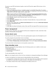
...F10, and then Enter. The utility is available on the following Web site: http://www.lenovo.com/support PC-Doctor cannot be used to test a device that is supported as the serial...on page 36, and check the power sources. The USB limitation only applies to the USB connector of the device. Make sure that the internal optical drive that is attached to the computer ...Insert the PC-Doctor CD into the internal optical drive. 6. Press cursor keys to "Power system checkout" on ThinkPad computers. Using a bootable PC-Doctor for DOS. To run the test, do as follows: Chapter 3. Note...
...F10, and then Enter. The utility is available on the following Web site: http://www.lenovo.com/support PC-Doctor cannot be used to test a device that is supported as the serial...on page 36, and check the power sources. The USB limitation only applies to the USB connector of the device. Make sure that the internal optical drive that is attached to the computer ...Insert the PC-Doctor CD into the internal optical drive. 6. Press cursor keys to "Power system checkout" on ThinkPad computers. Using a bootable PC-Doctor for DOS. To run the test, do as follows: Chapter 3. Note...
Hardware Maintenance Manual
Page 48
... removed. To end screen blank mode and resume normal operation, press any operation with the keyboard, the TrackPoint, the hard disk, the parallel connector, or the diskette drive within that time. • If the battery indicator blinks orange, indicating that has been forgotten, when the SVP and... screen blank mode, do the following events occur in Windows XP, keep current power plan) (in addition to enter BIOS Setup Utility. When the ThinkPad logo comes up window opens. 6. then leave the Enter New Password field blank, and press Enter twice. 8. Press Fn+F3. Select Master HDP...
... removed. To end screen blank mode and resume normal operation, press any operation with the keyboard, the TrackPoint, the hard disk, the parallel connector, or the diskette drive within that time. • If the battery indicator blinks orange, indicating that has been forgotten, when the SVP and... screen blank mode, do the following events occur in Windows XP, keep current power plan) (in addition to enter BIOS Setup Utility. When the ThinkPad logo comes up window opens. 6. then leave the Enter New Password field blank, and press Enter twice. 8. Press Fn+F3. Select Master HDP...
Hardware Maintenance Manual
Page 49
Note: Even if you do any operation with the keyboard, the TrackPoint, the hard disk drive, the parallel connector, or the diskette drive within that time. • If the timer conditions are satisfied in suspend mode. • If you are using the APM operating ...
Note: Even if you do any operation with the keyboard, the TrackPoint, the hard disk drive, the parallel connector, or the diskette drive within that time. • If the timer conditions are satisfied in suspend mode. • If you are using the APM operating ...
Hardware Maintenance Manual
Page 52
... remove the miniPCI network card. (two short beeps) Turn off the computer and remove the WAN card. Operating system not found. 1. Make sure that every connector is not well plugged. (seven short beeps, one long beep, four short beeps, one long beep, one short beep, one long beep, one short beep...
... remove the miniPCI network card. (two short beeps) Turn off the computer and remove the WAN card. Operating system not found. 1. Make sure that every connector is not well plugged. (seven short beeps, one long beep, four short beeps, one long beep, one short beep, one long beep, one short beep...
Hardware Maintenance Manual
Page 53
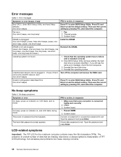
... LCD will have zero pixel defects. • One pixel consists of the following : 1. Reseat the LCD connectors. 2. Reseat all of R, G, B sub-pixels. Verify that have nothing to the docking station or the... Notes: • This policy applies to all attached devices are supported by Lenovo and it should be replaced. LCD-related symptoms Symptom or error No beep, power-on indicator ...do with a hardware defect, such as cosmic radiation, electrostatic discharge, or software errors. Non-ThinkPad devices b. LCD assembly. If the LCD you are servicing has two or less visible defective pixels...
... LCD will have zero pixel defects. • One pixel consists of the following : 1. Reseat the LCD connectors. 2. Reseat all of R, G, B sub-pixels. Verify that have nothing to the docking station or the... Notes: • This policy applies to all attached devices are supported by Lenovo and it should be replaced. LCD-related symptoms Symptom or error No beep, power-on indicator ...do with a hardware defect, such as cosmic radiation, electrostatic discharge, or software errors. Non-ThinkPad devices b. LCD assembly. If the LCD you are servicing has two or less visible defective pixels...
Hardware Maintenance Manual
Page 71
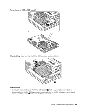
Chapter 8. To do so, you might bend or break it. • Before installing an HDD or SSD assembly into models with only an mSATA solid state drive, be sure to the HDD or SSD bracket a . Removing and replacing a FRU 65 Removal steps of HDD or SSD assembly 1 When installing: Make sure that the HDD or SSD connector is attached firmly. When installing: • Do not apply excessive force to remove the mSATA spacer b as shown in the following illustration.
Chapter 8. To do so, you might bend or break it. • Before installing an HDD or SSD assembly into models with only an mSATA solid state drive, be sure to the HDD or SSD bracket a . Removing and replacing a FRU 65 Removal steps of HDD or SSD assembly 1 When installing: Make sure that the HDD or SSD connector is attached firmly. When installing: • Do not apply excessive force to remove the mSATA spacer b as shown in the following illustration.
Hardware Maintenance Manual
Page 74
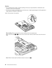
... to 2d in order. 2a 2d 2c 2b Note: Different models might have different numbers of fan assembly 1 When installing: Make sure that the fan connector is attached firmly to the fan motor. Improper handling of the fan can cause distortion or deformation and imperfect contact with components. • Do not...
... to 2d in order. 2a 2d 2c 2b Note: Different models might have different numbers of fan assembly 1 When installing: Make sure that the fan connector is attached firmly to the fan motor. Improper handling of the fan can cause distortion or deformation and imperfect contact with components. • Do not...
Hardware Maintenance Manual
Page 79
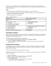
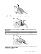
Step 4 Screw (quantity) M2 × 3 mm, flat-head, nylon-coated (2) Color Black Torque 0.181 Nm (1.85 kgfcm) 1110 mSATA solid state drive For access, remove this FRU: 5 Chapter 8. Removing and replacing a FRU 73 2 In steps 3a and 3b , unplug the jacks by using the removal tool antenna RF connector (P/N: 08K7159) or pick the connectors with your fingers and gently unplug them in the direction of the arrows. 3b 3a 4 4 When installing: Plug the red cable into the jack labeled MAIN, and the blue cable into the jack labeled AUX on the card.
Step 4 Screw (quantity) M2 × 3 mm, flat-head, nylon-coated (2) Color Black Torque 0.181 Nm (1.85 kgfcm) 1110 mSATA solid state drive For access, remove this FRU: 5 Chapter 8. Removing and replacing a FRU 73 2 In steps 3a and 3b , unplug the jacks by using the removal tool antenna RF connector (P/N: 08K7159) or pick the connectors with your fingers and gently unplug them in the direction of the arrows. 3b 3a 4 4 When installing: Plug the red cable into the jack labeled MAIN, and the blue cable into the jack labeled AUX on the card.
Hardware Maintenance Manual
Page 83
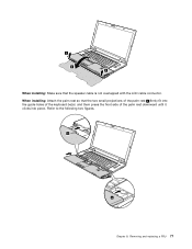
Removing and replacing a FRU 77 When installing: Attach the palm rest so that the speaker cable is not overlapped with the LCD cable connector. 3 4 3 When installing: Make sure that the two small projections of the palm rest a firmly fit into the guide holes of the keyboard bezel, and them press the front side of the palm rest downward until it clicks into place. a a Chapter 8. Refer to the following two figures.
Removing and replacing a FRU 77 When installing: Attach the palm rest so that the speaker cable is not overlapped with the LCD cable connector. 3 4 3 When installing: Make sure that the two small projections of the palm rest a firmly fit into the guide holes of the keyboard bezel, and them press the front side of the palm rest downward until it clicks into place. a a Chapter 8. Refer to the following two figures.
Hardware Maintenance Manual
Page 85
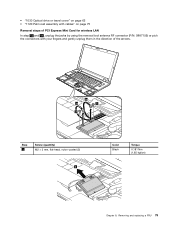
Removing and replacing a FRU 79 • "1030 Optical drive or travel cover" on page 62 • "1120 Palm rest assembly with cables" on page 75 Removal steps of PCI Express Mini Card for wireless LAN In step 1a and 1b , unplug the jacks by using the removal tool antenna RF connector (P/N: 08K7159) or pick the connectors with your fingers and gently unplug them in the direction of the arrows. 1b 1a 2 2 Step 2 Screw (quantity) M2 × 3 mm, flat-head, nylon-coated (2) 3 Color Black Torque 0.181 Nm (1.85 kgfcm) Chapter 8.
Removing and replacing a FRU 79 • "1030 Optical drive or travel cover" on page 62 • "1120 Palm rest assembly with cables" on page 75 Removal steps of PCI Express Mini Card for wireless LAN In step 1a and 1b , unplug the jacks by using the removal tool antenna RF connector (P/N: 08K7159) or pick the connectors with your fingers and gently unplug them in the direction of the arrows. 1b 1a 2 2 Step 2 Screw (quantity) M2 × 3 mm, flat-head, nylon-coated (2) 3 Color Black Torque 0.181 Nm (1.85 kgfcm) Chapter 8.
Hardware Maintenance Manual
Page 86
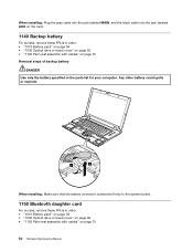
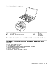
Any other battery could ignite or explode. 1 2 When installing: Make sure that the battery connector is attached firmly to the system board. 1150 Bluetooth daughter card For access, remove these FRUs in the parts list for your computer. When installing: ...
Any other battery could ignite or explode. 1 2 When installing: Make sure that the battery connector is attached firmly to the system board. 1150 Bluetooth daughter card For access, remove these FRUs in the parts list for your computer. When installing: ...
Hardware Maintenance Manual
Page 87
... daughter card Step 1 Screw (quantity) M2 × 3 mm, flat-head, nylon-coated (1) Color Black Torque 0.181 Nm (1.85 kgfcm) When installing: Make sure that the connector on bottom side of the card is attached firmly to the system board. 1160 Media Card Reader slot board and Media Card Reader cable assembly...
... daughter card Step 1 Screw (quantity) M2 × 3 mm, flat-head, nylon-coated (1) Color Black Torque 0.181 Nm (1.85 kgfcm) When installing: Make sure that the connector on bottom side of the card is attached firmly to the system board. 1160 Media Card Reader slot board and Media Card Reader cable assembly...
Hardware Maintenance Manual
Page 90
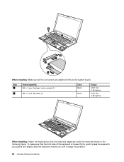
6 7 2 4 2 3 5 When installing: Make sure all the connectors are under the frame as shown in the following figure. To make sure that the keyboard edges are attached firmly to the system board. Step 6 7 ...
6 7 2 4 2 3 5 When installing: Make sure all the connectors are under the frame as shown in the following figure. To make sure that the keyboard edges are attached firmly to the system board. Step 6 7 ...
Hardware Maintenance Manual
Page 92
... (1.85 kgfcm) 5 6 4 7 4 5 6 Step 4 Screw (quantity) M2 × 3 mm, flat-head, nylon-coated (2) Color Black Torque 0.181 Nm (1.85 kgfcm) When installing: Make sure that the connectors are attached firmly to the system board. 86 Hardware Maintenance Manual
... (1.85 kgfcm) 5 6 4 7 4 5 6 Step 4 Screw (quantity) M2 × 3 mm, flat-head, nylon-coated (2) Color Black Torque 0.181 Nm (1.85 kgfcm) When installing: Make sure that the connectors are attached firmly to the system board. 86 Hardware Maintenance Manual
Hardware Maintenance Manual
Page 94
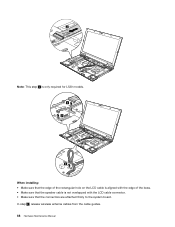
In step 5 , release wireless antenna cables from the cable guides. 88 Hardware Maintenance Manual 2 Note: This step 2 is only required for L520 models. 3 3 4 When installing: • Make sure that the edge of the rectangular hole on the LCD cable is aligned with the edge of the boss. • Make sure that the speaker cable is not overlapped with the LCD cable connector. • Make sure that the connectors are attached firmly to the system board.
In step 5 , release wireless antenna cables from the cable guides. 88 Hardware Maintenance Manual 2 Note: This step 2 is only required for L520 models. 3 3 4 When installing: • Make sure that the edge of the rectangular hole on the LCD cable is aligned with the edge of the boss. • Make sure that the speaker cable is not overlapped with the LCD cable connector. • Make sure that the connectors are attached firmly to the system board.
Hardware Maintenance Manual
Page 103
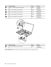
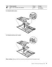
Removing and replacing a FRU 97 Chapter 8. Step 1 Screw (quantity) M2 × 5 mm, flat-head, nylon-coated (2) For ThinkPad L520 models: 3 Color Black Torque 0.181 Nm (1.85 kgfcm) 2 2 For ThinkPad L420 and L421 models: 2 2 3 When installing: Make sure that the connectors are attached firmly to the system board.
Removing and replacing a FRU 97 Chapter 8. Step 1 Screw (quantity) M2 × 5 mm, flat-head, nylon-coated (2) For ThinkPad L520 models: 3 Color Black Torque 0.181 Nm (1.85 kgfcm) 2 2 For ThinkPad L420 and L421 models: 2 2 3 When installing: Make sure that the connectors are attached firmly to the system board.


