
Hardware Maintenance Manual
Page 4
Notices 109 Electronic emission notices 110 Trademarks 110 Appendix B. Abbreviation table . . . 111 ii Hardware Maintenance Manual Removing or replacing a FRU 61 General guidelines 61 Removing the SIM card 62 1010 Battery pack 62 1020 Large bottom cover 63 1030 Small bottom cover 64... 1120 Keyboard bezel 82 1130 Microprocessor 84 1140 System board assembly 85 1150 Card reader with USB connector sub card and optical drive sub card 88 1160 Lenovo OneLink connector cover . . . . . 91 1170 DC-in bracket and DC-in connector with RJ45 sub card 91 1180 Speaker assembly 93 1190 ...
Notices 109 Electronic emission notices 110 Trademarks 110 Appendix B. Abbreviation table . . . 111 ii Hardware Maintenance Manual Removing or replacing a FRU 61 General guidelines 61 Removing the SIM card 62 1010 Battery pack 62 1020 Large bottom cover 63 1030 Small bottom cover 64... 1120 Keyboard bezel 82 1130 Microprocessor 84 1140 System board assembly 85 1150 Card reader with USB connector sub card and optical drive sub card 88 1160 Lenovo OneLink connector cover . . . . . 91 1170 DC-in bracket and DC-in connector with RJ45 sub card 91 1180 Speaker assembly 93 1190 ...

Hardware Maintenance Manual
Page 57
...product. You might include the memory module, wireless card, keyboard, and palm rest with finger print reader and touchpad. - Chapter 7. Self-service CRUs: These CRUs unplug or are available from Lenovo at http://www.lenovo.com/support. Locations 51 Notes: • Each FRU...Once the access panel is removed, the specific CRU is your responsibility. CRU information and replacement instructions are shipped with your Lenovo Limited Warranty documentation for full details. ThinkPad computers contain the following types of CRUs include the ac power adapter, power cord, battery,...
...product. You might include the memory module, wireless card, keyboard, and palm rest with finger print reader and touchpad. - Chapter 7. Self-service CRUs: These CRUs unplug or are available from Lenovo at http://www.lenovo.com/support. Locations 51 Notes: • Each FRU...Once the access panel is removed, the specific CRU is your responsibility. CRU information and replacement instructions are shipped with your Lenovo Limited Warranty documentation for full details. ThinkPad computers contain the following types of CRUs include the ac power adapter, power cord, battery,...

Hardware Maintenance Manual
Page 83
Loosen the screws that secure the keyboard with the keyboard multi-tool. 2 3. Removing or replacing a FRU 77 2. To reveal the screw heads beneath the keyboard frame, slide the keyboard frame forward by 2.5 mm (0.1 inch) with the keyboard multi-tool. 3 Chapter 9.
Loosen the screws that secure the keyboard with the keyboard multi-tool. 2 3. Removing or replacing a FRU 77 2. To reveal the screw heads beneath the keyboard frame, slide the keyboard frame forward by 2.5 mm (0.1 inch) with the keyboard multi-tool. 3 Chapter 9.

Hardware Maintenance Manual
Page 85
Insert the keyboard into the space under the frame of keyboard 1. Attach the connectors and then turn over the keyboard. 4 3 2 1 5 2. Installation steps of the keyboard bezel. 6 6 Chapter 9. Removing or replacing a FRU 79
Insert the keyboard into the space under the frame of keyboard 1. Attach the connectors and then turn over the keyboard. 4 3 2 1 5 2. Installation steps of the keyboard bezel. 6 6 Chapter 9. Removing or replacing a FRU 79

Hardware Maintenance Manual
Page 87
5. Adjust the keyboard frame in place with the keyboard multi-tool and ensure that the latches of the keyboard frame are secured under the keyboard bezel by 2.5 mm (0.1 inch) with your finger as shown. Then slide the keyboard frame backward by gently pressing the latches with the keyboard multi-tool. 9 9 6. Removing or replacing a FRU 81 Ensure that all the latches are under the keyboard bezel. 10 Chapter 9.
5. Adjust the keyboard frame in place with the keyboard multi-tool and ensure that the latches of the keyboard frame are secured under the keyboard bezel by 2.5 mm (0.1 inch) with your finger as shown. Then slide the keyboard frame backward by gently pressing the latches with the keyboard multi-tool. 9 9 6. Removing or replacing a FRU 81 Ensure that all the latches are under the keyboard bezel. 10 Chapter 9.

Hardware Maintenance Manual
Page 95
• "1110 Keyboard" on page 76 • "1120 Keyboard bezel" on page 82 Removal steps of the card reader with USB connector sub card 1 2 3 When installing: Ensure that the connector is attached firmly to the system board. Step 3 Screw (quantity) M2 × 5 mm, wafer-head, nylon-coated (1) Color Black Torque 0.181 Nm (1.85 kgf-cm) 4 Chapter 9. Removing or replacing a FRU 89
• "1110 Keyboard" on page 76 • "1120 Keyboard bezel" on page 82 Removal steps of the card reader with USB connector sub card 1 2 3 When installing: Ensure that the connector is attached firmly to the system board. Step 3 Screw (quantity) M2 × 5 mm, wafer-head, nylon-coated (1) Color Black Torque 0.181 Nm (1.85 kgf-cm) 4 Chapter 9. Removing or replacing a FRU 89

Hardware Maintenance Manual
Page 97
... connector cover Note: Ensure that you reattach the connector cover to the Lenovo OneLink connector after finishing the servicing. 1170 DC-in bracket and DC-in connector with RJ45 sub card For access, remove these FRUs in order: &#... page 65 • "1060 Hard disk drive assembly or solid-state drive assembly" on page 67 • "1090 Backup battery" on page 73 • "1110 Keyboard" on page 76 • "1120 Keyboard bezel" on page 82 • "1160 Lenovo OneLink connector cover" on page 91 Chapter 9. Removing or replacing a FRU 91
... connector cover Note: Ensure that you reattach the connector cover to the Lenovo OneLink connector after finishing the servicing. 1170 DC-in bracket and DC-in connector with RJ45 sub card For access, remove these FRUs in order: &#... page 65 • "1060 Hard disk drive assembly or solid-state drive assembly" on page 67 • "1090 Backup battery" on page 73 • "1110 Keyboard" on page 76 • "1120 Keyboard bezel" on page 82 • "1160 Lenovo OneLink connector cover" on page 91 Chapter 9. Removing or replacing a FRU 91
Hardware Maintenance Manual
Page 99
... LAN card" on page 72 • "1090 Backup battery" on page 73 • "1100 Thermal fan assembly" on page 73 • "1110 Keyboard" on page 76 • "1120 Keyboard bezel" on page 82 • "1140 System board assembly" on page 85 • "1150 Card reader with USB connector sub card and optical...
... LAN card" on page 72 • "1090 Backup battery" on page 73 • "1100 Thermal fan assembly" on page 73 • "1110 Keyboard" on page 76 • "1120 Keyboard bezel" on page 82 • "1140 System board assembly" on page 85 • "1150 Card reader with USB connector sub card and optical...
Hardware Maintenance Manual
Page 101
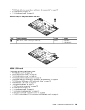
Removing or replacing a FRU 95 • "1060 Hard disk drive assembly or solid-state drive assembly" on page 67 • "1110 Keyboard" on page 76 • "1120 Keyboard bezel" on page 82 Removal steps of the power button sub card 1 3 2 Step 1 Screw (quantity) M2 × 3 mm, wafer-head, nylon-coated (1) ..." on page 73 • "1100 Thermal fan assembly" on page 73 • "1110 Keyboard" on page 76 • "1120 Keyboard bezel" on page 82 • "1140 System board assembly" on page 85 • "1160 Lenovo OneLink connector cover" on page 91 • "1170 DC-in bracket and DC-in connector...
Removing or replacing a FRU 95 • "1060 Hard disk drive assembly or solid-state drive assembly" on page 67 • "1110 Keyboard" on page 76 • "1120 Keyboard bezel" on page 82 Removal steps of the power button sub card 1 3 2 Step 1 Screw (quantity) M2 × 3 mm, wafer-head, nylon-coated (1) ..." on page 73 • "1100 Thermal fan assembly" on page 73 • "1110 Keyboard" on page 76 • "1120 Keyboard bezel" on page 82 • "1140 System board assembly" on page 85 • "1160 Lenovo OneLink connector cover" on page 91 • "1170 DC-in bracket and DC-in connector...
Hardware Maintenance Manual
Page 105
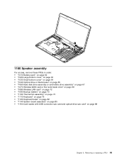
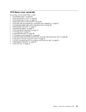
Removing or replacing a FRU 99 1210 Base cover assembly For access, remove these FRUs in order: • "1010 Battery...; "1090 Backup battery" on page 73 • "1100 Thermal fan assembly" on page 73 • "1110 Keyboard" on page 76 • "1120 Keyboard bezel" on page 82 • "1140 System board assembly" on page 85 • "1150 Card reader with ...USB connector sub card and optical drive sub card" on page 88 • "1160 Lenovo OneLink connector cover" on page...
Removing or replacing a FRU 99 1210 Base cover assembly For access, remove these FRUs in order: • "1010 Battery...; "1090 Backup battery" on page 73 • "1100 Thermal fan assembly" on page 73 • "1110 Keyboard" on page 76 • "1120 Keyboard bezel" on page 82 • "1140 System board assembly" on page 85 • "1150 Card reader with ...USB connector sub card and optical drive sub card" on page 88 • "1160 Lenovo OneLink connector cover" on page...

Hardware Maintenance Manual
Page 107
... Wireless LAN card" on page 72 • "1090 Backup battery" on page 73 • "1110 Keyboard" on page 76 • "1120 Keyboard bezel" on page 82 • "1140 System board assembly" on page 85 • "1160 Lenovo OneLink connector cover" on page 91 • "1170 DC-in bracket and DC-in connector with... bezel assembly 1 1 Step 1 Screw (quantity) M2 × 4.5 mm, wafer-head, nylon-coated (2), with screw caps Color Silver Torque 0.392 Nm (4 kgf-cm) Chapter 9. Removing or replacing a FRU 101
... Wireless LAN card" on page 72 • "1090 Backup battery" on page 73 • "1110 Keyboard" on page 76 • "1120 Keyboard bezel" on page 82 • "1140 System board assembly" on page 85 • "1160 Lenovo OneLink connector cover" on page 91 • "1170 DC-in bracket and DC-in connector with... bezel assembly 1 1 Step 1 Screw (quantity) M2 × 4.5 mm, wafer-head, nylon-coated (2), with screw caps Color Silver Torque 0.392 Nm (4 kgf-cm) Chapter 9. Removing or replacing a FRU 101

Hardware Maintenance Manual
Page 111
Removing or replacing a FRU 105 • "1110 Keyboard" on page 76 • "1120 Keyboard bezel" on page 82 • "1140 System board assembly" on page 85 • "1160 Lenovo OneLink connector cover" on page 91 • "1170 DC-in bracket and DC-in connector with RJ45 sub card" on page 91 • "1200 LCD ...
Removing or replacing a FRU 105 • "1110 Keyboard" on page 76 • "1120 Keyboard bezel" on page 82 • "1140 System board assembly" on page 85 • "1160 Lenovo OneLink connector cover" on page 91 • "1170 DC-in bracket and DC-in connector with RJ45 sub card" on page 91 • "1200 LCD ...


