
Hardware Maintenance Manual
Page 1
Hardware Maintenance Manual ThinkPad Edge 14², Edge 15², E40, and E50
Hardware Maintenance Manual ThinkPad Edge 14², Edge 15², E40, and E50
Hardware Maintenance Manual
Page 5
...problems effectively. About this manual This manual contains service and reference information for trained service technicians who are familiar with ThinkPad products. ThinkPad Edge 14" and E40 ThinkPad Edge 15" and E50 Machine types (MT) 0199, 0578, and 0579 MT 0301, 0302, and 0319 Use this...: This manual is intended only for the following ThinkPad® Notebook products. Before servicing a ThinkPad product, be sure to read all the information underChapter 1 "Safety information" on page 1 and Chapter 2 "Important service information" on page 23. © Copyright Lenovo 2010, 2012 iii
...problems effectively. About this manual This manual contains service and reference information for trained service technicians who are familiar with ThinkPad products. ThinkPad Edge 14" and E40 ThinkPad Edge 15" and E50 Machine types (MT) 0199, 0578, and 0579 MT 0301, 0302, and 0319 Use this...: This manual is intended only for the following ThinkPad® Notebook products. Before servicing a ThinkPad product, be sure to read all the information underChapter 1 "Safety information" on page 1 and Chapter 2 "Important service information" on page 23. © Copyright Lenovo 2010, 2012 iii
Hardware Maintenance Manual
Page 70
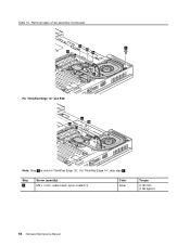
Table 13. For ThinkPad Edge 14", skip step 3 . Step 3 Screw (quantity) M2 × 4 mm, wafer-head, nylon-coated (1) Color Silver Torque 0.181 Nm (1.85 kgfcm) 64 Hardware Maintenance Manual Removal steps of fan assembly (continued) 2c 3 2b 2a 2e 2d 2f For ThinkPad Edge 14" and E40: 2c 2b 2a 2d Note: Step 3 is only for ThinkPad Edge 15".
Table 13. For ThinkPad Edge 14", skip step 3 . Step 3 Screw (quantity) M2 × 4 mm, wafer-head, nylon-coated (1) Color Silver Torque 0.181 Nm (1.85 kgfcm) 64 Hardware Maintenance Manual Removal steps of fan assembly (continued) 2c 3 2b 2a 2e 2d 2f For ThinkPad Edge 14" and E40: 2c 2b 2a 2d Note: Step 3 is only for ThinkPad Edge 15".

Hardware Maintenance Manual
Page 74
... those models, remove the SIM card as follows: After you insert the card back into the jack labeled AUX on the card. Removal steps of ThinkPad Edge 14", Edge 15", E40, and E50 might have the SIM card that you finish the servicing, make sure that the customer has been installed.
... those models, remove the SIM card as follows: After you insert the card back into the jack labeled AUX on the card. Removal steps of ThinkPad Edge 14", Edge 15", E40, and E50 might have the SIM card that you finish the servicing, make sure that the customer has been installed.
Hardware Maintenance Manual
Page 88
Table 25. Removal steps of LCD unit (continued) Steps 5a are for ThinkPad Edge 14" and E40, and steps 5b are for ThinkPad Edge 15" and E50. 5a 5b 5a 5b 5a 5a 5b 5b Step 5a or 5b Screw (quantity) M2.5 × 6.5 mm, wafter-head, nylon-coated (4) Color Black Torque 0.392 Nm (4 kgfcm) 82 Hardware Maintenance Manual
Table 25. Removal steps of LCD unit (continued) Steps 5a are for ThinkPad Edge 14" and E40, and steps 5b are for ThinkPad Edge 15" and E50. 5a 5b 5a 5b 5a 5a 5b 5b Step 5a or 5b Screw (quantity) M2.5 × 6.5 mm, wafter-head, nylon-coated (4) Color Black Torque 0.392 Nm (4 kgfcm) 82 Hardware Maintenance Manual

Hardware Maintenance Manual
Page 90
Table 26. Removal steps of top shielding assembly (continued) 12 3 2 2 2 3 2 4 Step 1 2 3 Screw (quantity) M2 × 2 mm, wafer-head, nylon-coated (3) M2 × 3 mm, wafer-head, nylon-coated (5) M2 × 5 mm, wafer-head, nylon-coated (2) For ThinkPad Edge 14" and E40: 1 2 2 3 3 3 3 4 Color Silver Black Black Torque 0.181 Nm (1.85 kgfcm) 0.181 Nm (1.85 kgfcm) 0.181 Nm (1.85 kgfcm) Step Screw (quantity) 84 Hardware Maintenance Manual Color Torque
Table 26. Removal steps of top shielding assembly (continued) 12 3 2 2 2 3 2 4 Step 1 2 3 Screw (quantity) M2 × 2 mm, wafer-head, nylon-coated (3) M2 × 3 mm, wafer-head, nylon-coated (5) M2 × 5 mm, wafer-head, nylon-coated (2) For ThinkPad Edge 14" and E40: 1 2 2 3 3 3 3 4 Color Silver Black Black Torque 0.181 Nm (1.85 kgfcm) 0.181 Nm (1.85 kgfcm) 0.181 Nm (1.85 kgfcm) Step Screw (quantity) 84 Hardware Maintenance Manual Color Torque
Hardware Maintenance Manual
Page 92
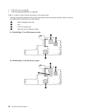
a GMCH (Integrated video chip) b CPU c ICH (I/O Controller Hub) d Video chip (only for discrete models) For ThinkPad Edge 14" and E40 integrated models: a b For ThinkPad Edge 14" and E40 discrete models: d c a b c 86 Hardware Maintenance Manual Location of major sensitive components on the system board Following components soldered on page 83 Table 27. • "1150 LCD unit" on page 80 • "1160 Top shielding assembly" on the top side of rough handling. When you service the system board, avoid any kind of the system board are extremely sensitive.
a GMCH (Integrated video chip) b CPU c ICH (I/O Controller Hub) d Video chip (only for discrete models) For ThinkPad Edge 14" and E40 integrated models: a b For ThinkPad Edge 14" and E40 discrete models: d c a b c 86 Hardware Maintenance Manual Location of major sensitive components on the system board Following components soldered on page 83 Table 27. • "1150 LCD unit" on page 80 • "1160 Top shielding assembly" on the top side of rough handling. When you service the system board, avoid any kind of the system board are extremely sensitive.
Hardware Maintenance Manual
Page 94
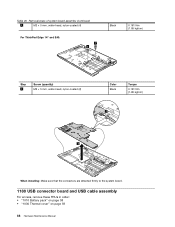
Removal steps of system board assembly (continued) 1 M2 × 5 mm, wafer-head, nylon-coated (4) For ThinkPad Edge 14" and E40: 1 1 Black 0.181 Nm (1.85 kgfcm) Step 1 Screw (quantity) M2 × 5 mm, wafer-head, nylon-coated (2) Color Black Torque 0.181 Nm (1.85 kgfcm) 2 3 When installing: Make sure that the connectors are attached firmly to the system board. 1180 USB connector board and USB cable assembly For access, remove these FRUs in order: • "1010 Battery pack" on page 58 • "1030 Thermal cover" on page 59 88 Hardware Maintenance Manual Table 28.
Removal steps of system board assembly (continued) 1 M2 × 5 mm, wafer-head, nylon-coated (4) For ThinkPad Edge 14" and E40: 1 1 Black 0.181 Nm (1.85 kgfcm) Step 1 Screw (quantity) M2 × 5 mm, wafer-head, nylon-coated (2) Color Black Torque 0.181 Nm (1.85 kgfcm) 2 3 When installing: Make sure that the connectors are attached firmly to the system board. 1180 USB connector board and USB cable assembly For access, remove these FRUs in order: • "1010 Battery pack" on page 58 • "1030 Thermal cover" on page 59 88 Hardware Maintenance Manual Table 28.
Hardware Maintenance Manual
Page 95
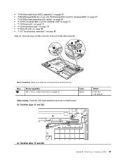
..." and E50: Torque 0.181 Nm (1.85 kgfcm) For ThinkPad Edge 14" and E40: Chapter 8. • "1040 Hard disk drive (HDD) assembly" on page 60 • "1080 Wireless WAN slot cover and PCI Express Mini Card for wireless WAN" ...
..." and E50: Torque 0.181 Nm (1.85 kgfcm) For ThinkPad Edge 14" and E40: Chapter 8. • "1040 Hard disk drive (HDD) assembly" on page 60 • "1080 Wireless WAN slot cover and PCI Express Mini Card for wireless WAN" ...

Hardware Maintenance Manual
Page 97
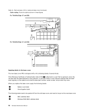
Table 30. Removing or replacing a FRU 91 Removal steps of DC-in cable and base cover (continued) 4 3 1 2 Step 1 Screw (quantity) M2 × 3 mm, wafer-head, nylon-coated (2) Color Black For ThinkPad Edge 14" and E40: 1 2 4 3 Torque 0.181 Nm (1.85 kgfcm) Step 1 Screw (quantity) M2 × 5 mm, wafer-head, nylon-coated (1) Color Black Torque 0.181 Nm (1.85 kgfcm) Chapter 8.
Table 30. Removing or replacing a FRU 91 Removal steps of DC-in cable and base cover (continued) 4 3 1 2 Step 1 Screw (quantity) M2 × 3 mm, wafer-head, nylon-coated (2) Color Black For ThinkPad Edge 14" and E40: 1 2 4 3 Torque 0.181 Nm (1.85 kgfcm) Step 1 Screw (quantity) M2 × 5 mm, wafer-head, nylon-coated (1) Color Black Torque 0.181 Nm (1.85 kgfcm) Chapter 8.
Hardware Maintenance Manual
Page 98
... customer, or provide a letter to the customer stating what the label part number, serial number, and product key were. Table 30. For ThinkPad Edge 15" and E50: For ThinkPad Edge 14" and E40: Applying labels to be peeled off from the old base cover, and need to the base cover The new base cover FRU is...
... customer, or provide a letter to the customer stating what the label part number, serial number, and product key were. Table 30. For ThinkPad Edge 15" and E50: For ThinkPad Edge 14" and E40: Applying labels to be peeled off from the old base cover, and need to the base cover The new base cover FRU is...

Hardware Maintenance Manual
Page 100
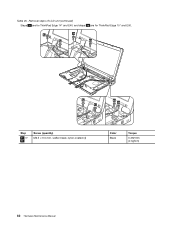
... bezel 1 1 1 1 Step 1 Screw cap Screw (quantity) M2 × 5 mm, wafer-head, nylon-coated (4) Color Black 94 Hardware Maintenance Manual Torque 0.181 Nm (1.85 kgfcm) For ThinkPad Edge 14" and E40: 1 2 3 4 12 5 11 6 7 10 9 8 2010 LCD front bezel For access, remove these FRUs in order: • "1010 Battery pack" on page 58 • "1080 Wireless...
... bezel 1 1 1 1 Step 1 Screw cap Screw (quantity) M2 × 5 mm, wafer-head, nylon-coated (4) Color Black 94 Hardware Maintenance Manual Torque 0.181 Nm (1.85 kgfcm) For ThinkPad Edge 14" and E40: 1 2 3 4 12 5 11 6 7 10 9 8 2010 LCD front bezel For access, remove these FRUs in order: • "1010 Battery pack" on page 58 • "1080 Wireless...
Hardware Maintenance Manual
Page 103
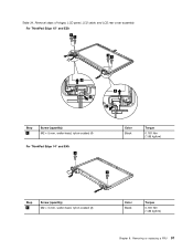
Removing or replacing a FRU 97 Removal steps of hinges, LCD panel, LCD cable, and LCD rear cover assembly For ThinkPad Edge 15" and E50: 1 1 11 2 2 2 2 Step 1 Screw (quantity) M2 × 5 mm, wafer-head, nylon-coated (4) For ThinkPad Edge 14" and E40: 1 Color Black Torque 0.181 Nm (1.85 kgfcm) 1 Step 1 Screw (quantity) M2 × 5 mm, wafer-head, nylon-coated (2) Color Black Torque 0.181 Nm (1.85 kgfcm) Chapter 8. Table 34.
Removing or replacing a FRU 97 Removal steps of hinges, LCD panel, LCD cable, and LCD rear cover assembly For ThinkPad Edge 15" and E50: 1 1 11 2 2 2 2 Step 1 Screw (quantity) M2 × 5 mm, wafer-head, nylon-coated (4) For ThinkPad Edge 14" and E40: 1 Color Black Torque 0.181 Nm (1.85 kgfcm) 1 Step 1 Screw (quantity) M2 × 5 mm, wafer-head, nylon-coated (2) Color Black Torque 0.181 Nm (1.85 kgfcm) Chapter 8. Table 34.

Hardware Maintenance Manual
Page 107
... 49. 7 AC power connector 8 Optical drive or travel cover 9 Universal serial bus (USB) connectors 10 Sleep (standby) status indicator Note: For the description of ThinkPad Edge 14", Edge 15", E40, and E50 features and hardware. Locations This chapter presents the location of the indicator, see Chapter 5 "Status indicators" on page 49. 11 Fingerprint reader (for...
... 49. 7 AC power connector 8 Optical drive or travel cover 9 Universal serial bus (USB) connectors 10 Sleep (standby) status indicator Note: For the description of ThinkPad Edge 14", Edge 15", E40, and E50 features and hardware. Locations This chapter presents the location of the indicator, see Chapter 5 "Status indicators" on page 49. 11 Fingerprint reader (for...

Hardware Maintenance Manual
Page 129
..." on page 138.) 22 Illuminated keyboard (see "AC adapters" on page 140.) LCD FRUs In ThinkPad Edge 14", Edge 15", E40, and E50, there are following types of LCDs. • 14.0-inch HD LED-backlight LCD (Table 37 "Parts list-14.0-inch HD LCD" on page 125) • 15.6-inch HD LED-backlight LCD (Table 38 "Parts...
..." on page 138.) 22 Illuminated keyboard (see "AC adapters" on page 140.) LCD FRUs In ThinkPad Edge 14", Edge 15", E40, and E50, there are following types of LCDs. • 14.0-inch HD LED-backlight LCD (Table 37 "Parts list-14.0-inch HD LCD" on page 125) • 15.6-inch HD LED-backlight LCD (Table 38 "Parts...


