

English - Hardware Maintenance Manual for 570 systems
Page 3
... Power management features 24 Checkout guide 27 Testing the computer 27 Detecting system information with PC-Doctor . . 28 Power system checkout 29 ThinkPad 570 and 570E 33 Product overview 35 Specifications 35 Status indicators 37 Structure 38 Fn key combinations 41 Symptom-to-FRU index 42 Numeric error codes 42 ... 48 Screw notices 48 Retaining serial numbers 49 Removing and replacing a FRU 51 1010 Battery pack 53 1020 Backup battery 54 1030 DIMM 56 1040 Hard disk drive 57 1050 Keyboard 59 1060 Center cover 61 1070 Modem card 62 Copyright IBM Corp. 2000 iii
... Power management features 24 Checkout guide 27 Testing the computer 27 Detecting system information with PC-Doctor . . 28 Power system checkout 29 ThinkPad 570 and 570E 33 Product overview 35 Specifications 35 Status indicators 37 Structure 38 Fn key combinations 41 Symptom-to-FRU index 42 Numeric error codes 42 ... 48 Screw notices 48 Retaining serial numbers 49 Removing and replacing a FRU 51 1010 Battery pack 53 1020 Backup battery 54 1030 DIMM 56 1040 Hard disk drive 57 1050 Keyboard 59 1060 Center cover 61 1070 Modem card 62 Copyright IBM Corp. 2000 iii
English - Hardware Maintenance Manual for 570 systems
Page 37
... 48 Retaining serial numbers 49 Removing and replacing a FRU 51 1010 Battery pack 53 1020 Backup battery 54 1030 DIMM 56 1040 Hard disk drive 57 1050 Keyboard 59 1060 Center cover 61 1070 Modem card 62 1080 Frame and power switch 63 1090 Audio card 65 1100 Modem jack 66 1110... UltraBase 93 Locations 94 Front view 94 Rear view 96 Bottom view 97 Password pads 98 Parts List 99 Copyright IBM Corp. 2000 33 ThinkPad 570 and 570E ThinkPad 570 and 570E This chapter includes the descriptions for the...
... 48 Retaining serial numbers 49 Removing and replacing a FRU 51 1010 Battery pack 53 1020 Backup battery 54 1030 DIMM 56 1040 Hard disk drive 57 1050 Keyboard 59 1060 Center cover 61 1070 Modem card 62 1080 Frame and power switch 63 1090 Audio card 65 1100 Modem jack 66 1110... UltraBase 93 Locations 94 Front view 94 Rear view 96 Bottom view 97 Password pads 98 Parts List 99 Copyright IBM Corp. 2000 33 ThinkPad 570 and 570E ThinkPad 570 and 570E This chapter includes the descriptions for the...
English - Hardware Maintenance Manual for 570 systems
Page 85
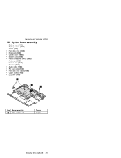
Removing and replacing a FRU 1180 System board assembly Battery pack (1010) Backup battery (1020) DIMM (1030) Hard disk drive (1040) Keyboard (1050) Center cover (1060) Modem card (1070) Frame and power switch (1080) Audio card (1090) Modem jack (1100) Speaker (1110) Audio cable (1120) PC Card slots (1130) Hard disk drive cable (1140) Upper shield (1150) LCD unit (1170) Step 1 Screw (quantity) M2.5 x 4.8 mm (4) Torque 4 kgcm ThinkPad 570 and 570E 81
Removing and replacing a FRU 1180 System board assembly Battery pack (1010) Backup battery (1020) DIMM (1030) Hard disk drive (1040) Keyboard (1050) Center cover (1060) Modem card (1070) Frame and power switch (1080) Audio card (1090) Modem jack (1100) Speaker (1110) Audio cable (1120) PC Card slots (1130) Hard disk drive cable (1140) Upper shield (1150) LCD unit (1170) Step 1 Screw (quantity) M2.5 x 4.8 mm (4) Torque 4 kgcm ThinkPad 570 and 570E 81
English - Hardware Maintenance Manual for 570 systems
Page 86
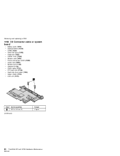
Removing and replacing a FRU 1190 I/O Connector cable or system board Battery pack (1010) Backup battery (1020) DIMM (1030) Hard disk drive (1040) Keyboard (1050) Center cover (1060) Modem card (1070) Frame and power switch (1080) Audio card (1090) Modem jack (1100) Speaker (1110) Audio cable (1120) PC Card slots (1130) Hard disk drive cable (1140) Upper shield (1150) LCD unit (1170) Step 1 Screw (quantity) M2.5 x 4.8 mm (2) (continued) Torque 4 kgcm 82 ThinkPad 570 and 570E Hardware Maintenance Manual
Removing and replacing a FRU 1190 I/O Connector cable or system board Battery pack (1010) Backup battery (1020) DIMM (1030) Hard disk drive (1040) Keyboard (1050) Center cover (1060) Modem card (1070) Frame and power switch (1080) Audio card (1090) Modem jack (1100) Speaker (1110) Audio cable (1120) PC Card slots (1130) Hard disk drive cable (1140) Upper shield (1150) LCD unit (1170) Step 1 Screw (quantity) M2.5 x 4.8 mm (2) (continued) Torque 4 kgcm 82 ThinkPad 570 and 570E Hardware Maintenance Manual

English - Hardware Maintenance Manual for 570 systems
Page 105
... drive cable 08K6379 Holder, hard disk drive (570E) 05K6294 Cover*, hard disk drive 05K6072 Bracket, hard disk drive 05K4752 19 Fan (570) 05K6065 Fan (570E) 05K6293 20 Upper shield (570) 05K6064 Upper shield (570E) 05K6290 21 Diskette drive* (TEAC) 05K8989 21 Diskette drive* (SONY) 05K8990 22 Cable*, diskette drive 05K2844 (continued) ThinkPad 570 and 570E 101 Parts list No.
... drive cable 08K6379 Holder, hard disk drive (570E) 05K6294 Cover*, hard disk drive 05K6072 Bracket, hard disk drive 05K4752 19 Fan (570) 05K6065 Fan (570E) 05K6293 20 Upper shield (570) 05K6064 Upper shield (570E) 05K6290 21 Diskette drive* (TEAC) 05K8989 21 Diskette drive* (SONY) 05K8990 22 Cable*, diskette drive 05K2844 (continued) ThinkPad 570 and 570E 101 Parts list No.

ThinkPad 570 User's Reference
Page 21
...enables you to connect any object in front of these louvers. 6 The power switch turns the computer on your computer to a ThinkPad 570 UltraBase or to a ThinkPad 570 Direct Dock Adapter for connection to the USB interface. You can be attached to the computer. An external keyboard can use the... to this new standard. 8 To install or remove the SDRAM dual inline memory module (DIMM) option, loosen this memory-slot-cover screw. 9 The memory slot accepts an SDRAM dual inline memory module (DIMM) option. 1 To install or remove the hard disk, loosen this connector through an optional...
...enables you to connect any object in front of these louvers. 6 The power switch turns the computer on your computer to a ThinkPad 570 UltraBase or to a ThinkPad 570 Direct Dock Adapter for connection to the USB interface. You can be attached to the computer. An external keyboard can use the... to this new standard. 8 To install or remove the SDRAM dual inline memory module (DIMM) option, loosen this memory-slot-cover screw. 9 The memory slot accepts an SDRAM dual inline memory module (DIMM) option. 1 To install or remove the hard disk, loosen this connector through an optional...

ThinkPad 570 User's Reference
Page 72
... screw and remove the memory slot cover. 4 Press out on the latches on both edges of the socket at the same time. 5 Remove the DIMM. Increasing memory Removing the DIMM 1 Power off the computer and disconnect the AC Adapter and all the cables you disconnected. 56 IBM ThinkPad 570 User's Reference then connect the AC...
... screw and remove the memory slot cover. 4 Press out on the latches on both edges of the socket at the same time. 5 Remove the DIMM. Increasing memory Removing the DIMM 1 Power off the computer and disconnect the AC Adapter and all the cables you disconnected. 56 IBM ThinkPad 570 User's Reference then connect the AC...


