ThinkPad 390 Remove Hard Drive - Lenovo
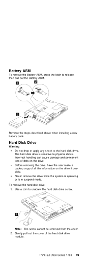
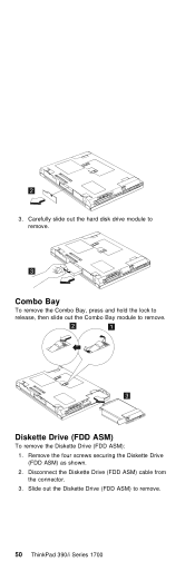
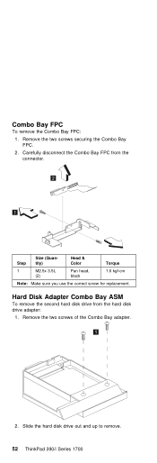
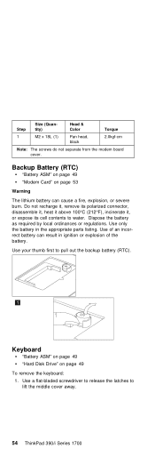
ThinkPad 390 Remove Hard Drive

View Results Below
Free Lenovo ThinkPad 390 manuals!
Problems with Lenovo ThinkPad 390?
Ask a Question
Free Lenovo ThinkPad 390 manuals!
Problems with Lenovo ThinkPad 390?
Ask a Question
Related Manual Pages

Similar Questions


Related Terms
The following terms were also used when searching for ThinkPad 390 Remove Hard Drive - Lenovo:- thinkpad 390 review
- thinkpad 390e battery won't keep charge
- thinkpad 390e battery
- thinkpad 390e ac adapter
- thinkpad 390e 2626
- thinkpad 390e
- thinkpad 390 ubuntu
- thinkpad 390 specs
- thinkpad 390 specifications
- thinkpad 390e bios update
- thinkpad 390 remove hard drive
- thinkpad 390 ram
- thinkpad 390 memory
- thinkpad 390 manual
- thinkpad 390 linux
- thinkpad 390 hard drive
- thinkpad 390 drivers
- thinkpad 390 driver
- thinkpad 390e drivers
- thinkpad 390e manual
- thinkpad 390e memory
- thinkpad 390e ram
- thinkpad 390e specifications
- thinkpad 390x
- thinkpad 390x battery
- thinkpad 390x bios
- thinkpad 390x driver
- thinkpad 390x drivers
- thinkpad 390x memory
- thinkpad 390x specifications
- thinkpad 390x support
- thinkpad x390
- thinkpad x390 ram upgrade
- lenovo ibm thinkpad 390 battery
- lenovo thinkpad 390 specs
- lenovo thinkpad 390 memory
- lenovo thinkpad 390 battery
- lenovo ibm thinkpad 390e
- lenovo ibm thinkpad 390 manual
- lenovo ibm thinkpad 390 laptop
- lenovo ibm thinkpad 390 e
- lenovo ibm thinkpad 390 drivers
- lenovo thinkpad 390e
- ibm thinkpad 390x
- ibm thinkpad 390e
- ibm thinkpad 390 manual
- ibm thinkpad 390 laptop
- ibm thinkpad 390 e
- ibm thinkpad 390 drivers
- ibm thinkpad 390 battery
- ibm lenovo thinkpad 390x
- lenovo thinkpad 390e ac adapter
- lenovo thinkpad 390e drivers
- lenovo thinkpad 390x
- lenovo thinkpad 390x bios
- lenovo thinkpad x390
- notebook lenovo thinkpad 390e
- notebook thinkpad 390e
- thinkpad 390
- thinkpad 390 backup battery
- thinkpad 390 battery
- thinkpad 390 bios
- thinkpad 390 bios battery
- thinkpad 390 bios password
- thinkpad 390 caddy
- thinkpad 390 cmos battery