
User Manual
Page 12
...one or more varies by model) v PCI Express adapter card slot (varies by model) Power v 280 Watt, 310 Watt manual and auto v 280 Watt, 220 Watt manual and auto v 280 Watt, power supply with auto-sensing voltage-selection switch v Automatic 50/60 Hz input frequency switching v Advanced ...Configuration and Power Interface (ACPI) support Security features v User and administrator passwords for BIOS access v Support ...
...one or more varies by model) v PCI Express adapter card slot (varies by model) Power v 280 Watt, 310 Watt manual and auto v 280 Watt, 220 Watt manual and auto v 280 Watt, power supply with auto-sensing voltage-selection switch v Automatic 50/60 Hz input frequency switching v Advanced ...Configuration and Power Interface (ACPI) support Security features v User and administrator passwords for BIOS access v Support ...
Hardware Maintenance Manual
Page 5
... Chapter 9. Replacing FRUs (Types 7064, 7094, 9349, 9356, 9357, 9439, 9488, 9702, 9708, 9709, 9789, 9851, 9948 91 © Copyright Lenovo 2005, 2010 v Safety information . . . . . 3 General safety 3 Electrical safety 3 Voltage-selection switch 5 Safety inspection guide 5 Handling electrostatic discharge-... Running tests 37 Viewing the test log 38 Chapter 6. Symptom-to-FRU Index . 45 Hard disk drive boot error 45 Power Supply Problems 45 Diagnostic error codes 46 Beep symptoms 63 POST error codes 64 Miscellaneous error messages 65 Undetermined problems 67 Chapter 8. ...
... Chapter 9. Replacing FRUs (Types 7064, 7094, 9349, 9356, 9357, 9439, 9488, 9702, 9708, 9709, 9789, 9851, 9948 91 © Copyright Lenovo 2005, 2010 v Safety information . . . . . 3 General safety 3 Electrical safety 3 Voltage-selection switch 5 Safety inspection guide 5 Handling electrostatic discharge-... Running tests 37 Viewing the test log 38 Chapter 6. Symptom-to-FRU Index . 45 Hard disk drive boot error 45 Power Supply Problems 45 Diagnostic error codes 46 Beep symptoms 63 POST error codes 64 Miscellaneous error messages 65 Undetermined problems 67 Chapter 8. ...

Hardware Maintenance Manual
Page 6
...11. FRU lists 143 Machine Type 6176 143 Machine Type 6177 158 Machine Type 6178 173 Machine Type 6179 187 vi ThinkCentre Hardware Maintenance Manual Machine Type 6305 202 Machine Type 7064 218 Machine Type 7065 233 Machine Type 7066 248 Machine Type... connectors 91 Computer components 92 System board connectors 92 Removing the cover 93 Removing and replacing the front bezel . . . . . 94 Replacing the power supply 95 Replacing the system board 96 Replacing the microprocessor 100 Replacing a memory module 103 Replacing a PCI adapter 104 Replacing the primary hard disk drive. ....
...11. FRU lists 143 Machine Type 6176 143 Machine Type 6177 158 Machine Type 6178 173 Machine Type 6179 187 vi ThinkCentre Hardware Maintenance Manual Machine Type 6305 202 Machine Type 7064 218 Machine Type 7065 233 Machine Type 7066 248 Machine Type... connectors 91 Computer components 92 System board connectors 92 Removing the cover 93 Removing and replacing the front bezel . . . . . 94 Replacing the power supply 95 Replacing the system board 96 Replacing the microprocessor 100 Replacing a memory module 103 Replacing a PCI adapter 104 Replacing the primary hard disk drive. ....

Hardware Maintenance Manual
Page 12
... mats that has hazardous voltages. • Disconnect all power before: - Remember: There must be a complete circuit to get medical aid. 4 ThinkCentre Hardware Maintenance Manual these hazards are moist floors, nongrounded power extension cables, power surges, and missing safety grounds. • Do not... that does not insulate you can cause personal injury and machine damage. • Do not service the following precautions: - Power supply units - Blowers and fans - If an electrical accident occurs, you when working with very high voltages; Performing a mechanical inspection - Some...
... mats that has hazardous voltages. • Disconnect all power before: - Remember: There must be a complete circuit to get medical aid. 4 ThinkCentre Hardware Maintenance Manual these hazards are moist floors, nongrounded power extension cables, power surges, and missing safety grounds. • Do not... that does not insulate you can cause personal injury and machine damage. • Do not service the following precautions: - Power supply units - Blowers and fans - If an electrical accident occurs, you when working with very high voltages; Performing a mechanical inspection - Some...

Hardware Maintenance Manual
Page 14
... or tampered with other liquids, or signs of any frame ground, ground braid, or green-wire ground. - Make sure that the power-supply cover fasteners (screws or rivets) have been certified (ISO 9000) as to the safety of fire or smoke damage. 7. 5. ESD...following languages: • English • Arabic • Brazilian/Portuguese • Chinese (simplified) • Chinese (traditional) • French 6 ThinkCentre Hardware Maintenance Manual Check that the ESD protective devices you are all at the same charge. 1. Use an ESD common ground or reference point when...
... or tampered with other liquids, or signs of any frame ground, ground braid, or green-wire ground. - Make sure that the power-supply cover fasteners (screws or rivets) have been certified (ISO 9000) as to the safety of fire or smoke damage. 7. 5. ESD...following languages: • English • Arabic • Brazilian/Portuguese • Chinese (simplified) • Chinese (traditional) • French 6 ThinkCentre Hardware Maintenance Manual Check that the ESD protective devices you are all at the same charge. 1. Use an ESD common ground or reference point when...

Hardware Maintenance Manual
Page 16
...turn off the electrical current supplied to the device. There are installed, note the following : Laser radiation when open. To remove all electrical current from the device, ensure that all power cords are disconnected from the power source. 2 1 8 ThinkCentre Hardware Maintenance Manual DANGER Some ... lbs) ≥55 kg (121.2 lbs) CAUTION: Use safe practices when lifting. CAUTION: The power control button on the device and the power switch on the power supply do not view directly with optical instruments, and avoid direct exposure to hazardous laser radiation. Removing the covers...
...turn off the electrical current supplied to the device. There are installed, note the following : Laser radiation when open. To remove all electrical current from the device, ensure that all power cords are disconnected from the power source. 2 1 8 ThinkCentre Hardware Maintenance Manual DANGER Some ... lbs) ≥55 kg (121.2 lbs) CAUTION: Use safe practices when lifting. CAUTION: The power control button on the device and the power switch on the power supply do not view directly with optical instruments, and avoid direct exposure to hazardous laser radiation. Removing the covers...

Hardware Maintenance Manual
Page 53
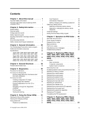
...drive is listed first. Chapter 7. Using the operating systems programs, format the hard disk drive. Power Supply Problems If you are unable to -FRU index lists error symptoms and possible causes. Check/Verify Check the following procedures...power problem, use the following for proper installation. • Power Cord • On/Off Switch connector • On/Off Switch Power Supply connector • System Board Power Supply connectors • Microprocessor(s) connection Check the power cord for continuity. Install an operating system on Switch © Copyright Lenovo...
...drive is listed first. Chapter 7. Using the operating systems programs, format the hard disk drive. Power Supply Problems If you are unable to -FRU index lists error symptoms and possible causes. Check/Verify Check the following procedures...power problem, use the following for proper installation. • Power Cord • On/Off Switch connector • On/Off Switch Power Supply connector • System Board Power Supply connectors • Microprocessor(s) connection Check the power cord for continuity. Install an operating system on Switch © Copyright Lenovo...

Hardware Maintenance Manual
Page 63
...-test. System board No action 1. System board Chapter 7. Flash the system and re-test. Reseat IDE signal cable 4. Go to review the log file 2. Check power supply voltages 3. Riser card, if installed 3. IDE signal cable 2. Press F3 to "Undetermined problems" on page 67 2. Re-start the test, if necessary 1. If a component is...
...-test. System board No action 1. System board Chapter 7. Flash the system and re-test. Reseat IDE signal cable 4. Go to review the log file 2. Check power supply voltages 3. Riser card, if installed 3. IDE signal cable 2. Press F3 to "Undetermined problems" on page 67 2. Re-start the test, if necessary 1. If a component is...

Hardware Maintenance Manual
Page 64
... Information" on page 775 3. Flash the system. System board 1. Replace component under test 1. SCSI adapter card, if installed 5. SCSI signal cable 2. Check power supply 3. SCSI device 4. System board 56 ThinkCentre Hardware Maintenance Manual Replace the component that is called out in warning statement 4. Go to review the log file 2. Press F3 to "Undetermined... 1. See "Updating (flashing) BIOS from a CD-ROM or diskette" on page 41 2. Go to reset the log file 1. Re-start the test, if necessary 1. Check power supply 3.
... Information" on page 775 3. Flash the system. System board 1. Replace component under test 1. SCSI adapter card, if installed 5. SCSI signal cable 2. Check power supply 3. SCSI device 4. System board 56 ThinkCentre Hardware Maintenance Manual Replace the component that is called out in warning statement 4. Go to review the log file 2. Press F3 to "Undetermined... 1. See "Updating (flashing) BIOS from a CD-ROM or diskette" on page 41 2. Go to reset the log file 1. Re-start the test, if necessary 1. Check power supply 3.

Hardware Maintenance Manual
Page 65
... Recovery Information" on page 41 2. RAID signal cable 2. System board Information only Re-start the test to review the log file 2. SCSI signal cable 2. Check power supply 3. Press F3 to -FRU Index 57 Make sure the component that is connected and/or enabled. Press F3 to reset the log file 1. Re-start...
... Recovery Information" on page 41 2. RAID signal cable 2. System board Information only Re-start the test to review the log file 2. SCSI signal cable 2. Check power supply 3. Press F3 to -FRU Index 57 Make sure the component that is connected and/or enabled. Press F3 to reset the log file 1. Re-start...

Hardware Maintenance Manual
Page 69
..., error threshold exceeded 175-197-XXX Thermal Sensor(s) test warning 175-198-XXX Thermal Sensor(s) test aborted FRU/Action 1. Flash the system and re-test. Power supply 2. System board No action 1. See "Updating (flashing) BIOS from a CD-ROM or diskette" on page 775 3. Flash system 2. Press F3 to "Undetermined problems" on page...
..., error threshold exceeded 175-197-XXX Thermal Sensor(s) test warning 175-198-XXX Thermal Sensor(s) test aborted FRU/Action 1. Flash the system and re-test. Power supply 2. System board No action 1. See "Updating (flashing) BIOS from a CD-ROM or diskette" on page 775 3. Flash system 2. Press F3 to "Undetermined problems" on page...

Hardware Maintenance Manual
Page 70
... action 1. Flash system 2. Microprocessor No action 1. Reseat the hard disk drive cable 4. System board 3. Check power supply voltages 3. System board 62 ThinkCentre Hardware Maintenance Manual Diagnostic Error Code 175-199-XXX Thermal Sensor(s) test failed, cause unknown 175-250-XXX 175... 1. Assure Asset Security Enabled 2. Diskette Drive Cable 2. Replace the memory module called out by the test 2. Diskette drive 4. Check power supply voltages 3. Microprocessor 4. System board No action 1. Cache, if removable 2. Hard Disk Drive Cable 2. Flash the system and re-test...
... action 1. Flash system 2. Microprocessor No action 1. Reseat the hard disk drive cable 4. System board 3. Check power supply voltages 3. System board 62 ThinkCentre Hardware Maintenance Manual Diagnostic Error Code 175-199-XXX Thermal Sensor(s) test failed, cause unknown 175-250-XXX 175... 1. Assure Asset Security Enabled 2. Diskette Drive Cable 2. Replace the memory module called out by the test 2. Diskette drive 4. Check power supply voltages 3. Microprocessor 4. System board No action 1. Cache, if removable 2. Hard Disk Drive Cable 2. Flash the system and re-test...

Hardware Maintenance Manual
Page 71
... Monitor DDC Test Passed 305-250-XXX Monitor DDC self test failure 415-000-XXXModem Test Passed 415-XXX-XXX Modem error FRU/Action 1. Check power supply voltages 3. Remove the Hi-Capacity Cartridge Drive and re-test the system 1. The following tables describes beep symptoms. Beep Symptom 2 short beeps CMOS setting error...
... Monitor DDC Test Passed 305-250-XXX Monitor DDC self test failure 415-000-XXXModem Test Passed 415-XXX-XXX Modem error FRU/Action 1. Check power supply voltages 3. Remove the Hi-Capacity Cartridge Drive and re-test the system 1. The following tables describes beep symptoms. Beep Symptom 2 short beeps CMOS setting error...

Hardware Maintenance Manual
Page 74
... LAN® 3. Run the Memory tests 2. Diskette Drive Cable 3. See "Hard disk drive boot error" on page 1. System Board Power-on indicator or hard disk drive in Setup/Configuration (see "Starting the Setup Utility program" on , 1. Ensure network administrator is active... display) 2. Diskette Drive Cable Other display symptoms not listed above (including blank 1. System Board 66 ThinkCentre Hardware Maintenance Manual Primary Hard Disk Drive 3. Check power supply and signal cable connections to enable Wake on or does not light when drive is using correct MAC ...
... LAN® 3. Run the Memory tests 2. Diskette Drive Cable 3. See "Hard disk drive boot error" on page 1. System Board Power-on indicator or hard disk drive in Setup/Configuration (see "Starting the Setup Utility program" on , 1. Ensure network administrator is active... display) 2. Diskette Drive Cable Other display symptoms not listed above (including blank 1. System Board 66 ThinkCentre Hardware Maintenance Manual Primary Hard Disk Drive 3. Check power supply and signal cable connections to enable Wake on or does not light when drive is using correct MAC ...
Hardware Maintenance Manual
Page 75
...External Cache RAM g. Message/Symptom FRU/Action Program loads from its own hard 1. Run Setup and check Startup sequence. 2. Power Supply RPL computer cannot access programs from the hard disk with a known-good diagnostics diskette in the first 3.5-inch diskette drive 1. ...mouse) b. Memory modules d. Symptom-to re-test the system. 4. Diskette Drive Cable 4. Keyboard Cable 3. Extended video memory e. External Cache f. Power-on the keyboard do not work 1. Repeat steps 1 through 3 until you find the failing device or adapter. network b. System Board Serial or ...
...External Cache RAM g. Message/Symptom FRU/Action Program loads from its own hard 1. Run Setup and check Startup sequence. 2. Power Supply RPL computer cannot access programs from the hard disk with a known-good diagnostics diskette in the first 3.5-inch diskette drive 1. ...mouse) b. Memory modules d. Symptom-to re-test the system. 4. Diskette Drive Cable 4. Keyboard Cable 3. Extended video memory e. External Cache f. Power-on the keyboard do not work 1. Repeat steps 1 through 3 until you find the failing device or adapter. network b. System Board Serial or ...

Hardware Maintenance Manual
Page 78
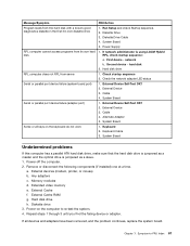
... locate the major FRUs in the computer. 1 Fan plenum, fan, and heat sink 2 Microprocessor 3 Optical drive 4 Power switch/LED assembly 5 Hard disk drive 6 Diskette drive 7 Front panel card 8 Memory modules 9 System board 10 Power supply System board connectors This illustration is to help locate the various system board connectors. 70 ThinkCentre Hardware Maintenance Manual
... locate the major FRUs in the computer. 1 Fan plenum, fan, and heat sink 2 Microprocessor 3 Optical drive 4 Power switch/LED assembly 5 Hard disk drive 6 Diskette drive 7 Front panel card 8 Memory modules 9 System board 10 Power supply System board connectors This illustration is to help locate the various system board connectors. 70 ThinkCentre Hardware Maintenance Manual

Hardware Maintenance Manual
Page 83
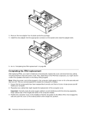
... the first time after replacing the battery. 7. Remove the screws that were removed. This is turned on a power supply or any component that secure the power supply. This procedure describes how to remove the power supply. 6. Replacing FRUs (Types 7065, 7096, 9351, 9358, 9438, 9481, 9489, 9703, 9784, 9788, ...replacement, an error message might be moved out of the chassis, remove the three screws that has this label attached. Replacing the power supply Attention Never remove the cover on for your machine type at the front. See "Removing the cover" on page 71. 2. ...
... the first time after replacing the battery. 7. Remove the screws that were removed. This is turned on a power supply or any component that secure the power supply. This procedure describes how to remove the power supply. 6. Replacing FRUs (Types 7065, 7096, 9351, 9358, 9438, 9481, 9489, 9703, 9784, 9788, ...replacement, an error message might be moved out of the chassis, remove the three screws that has this label attached. Replacing the power supply Attention Never remove the cover on for your machine type at the front. See "Removing the cover" on page 71. 2. ...

Hardware Maintenance Manual
Page 84
... the switch to 115 V. • If the voltage supply range in the PCI connectors. 76 ThinkCentre Hardware Maintenance Manual Remove any diskette drive and optical drive cables that it into position. 15. Route the power supply cable through the cable clamps underneath the hard disk drive ...and reconnect all power supply cables to "Completing the FRU ...
... the switch to 115 V. • If the voltage supply range in the PCI connectors. 76 ThinkCentre Hardware Maintenance Manual Remove any diskette drive and optical drive cables that it into position. 15. Route the power supply cable through the cable clamps underneath the hard disk drive ...and reconnect all power supply cables to "Completing the FRU ...
Hardware Maintenance Manual
Page 96
... until it snaps into the appropriate connector on the FRU that all power supply cables to "Completing the FRU replacement" on for a few seconds and then turn off. Install the new adapter into position. 88 ThinkCentre Hardware Maintenance Manual Go to avoid interference with the drive bay assembly.... Note: When the power cord is a normal sequence to enable the computer to confirm the updated information in , the...
... until it snaps into the appropriate connector on the FRU that all power supply cables to "Completing the FRU replacement" on for a few seconds and then turn off. Install the new adapter into position. 88 ThinkCentre Hardware Maintenance Manual Go to avoid interference with the drive bay assembly.... Note: When the power cord is a normal sequence to enable the computer to confirm the updated information in , the...

Hardware Maintenance Manual
Page 99
... of the connectors on page 1. and components of the computer. 1 Power supply diagnostic LEDs (some 10 models) 2 Voltage selection switch (some 11 models) 3 Power connector 12 4 Standard mouse connector 13 Ethernet connector USB connectors (2) Microphone connector Audio line out connector © Copyright Lenovo 2005, 2010 91 Rear connectors The following illustrations help you work...
... of the connectors on page 1. and components of the computer. 1 Power supply diagnostic LEDs (some 10 models) 2 Voltage selection switch (some 11 models) 3 Power connector 12 4 Standard mouse connector 13 Ethernet connector USB connectors (2) Microphone connector Audio line out connector © Copyright Lenovo 2005, 2010 91 Rear connectors The following illustrations help you work...


