
Hardware Maintenance Manual for ThinkCentre A70
Page 10
...high voltages. • Regularly inspect and maintain your work on suitable rubber mats (obtained locally, if necessary) to get medical aid. 4 ThinkCentre Hardware Maintenance Manual Pumps - First, check that it , ask the customer to power-off the wall box that power has been disconnected from... sections of maintenance information. Blowers and fans - Do not use this type of a plastic dental mirror. Working near equipment that contain small conductive fibers to work area. Use only one hand when working with live electrical circuits with the power-off the power, if necessary....
...high voltages. • Regularly inspect and maintain your work on suitable rubber mats (obtained locally, if necessary) to get medical aid. 4 ThinkCentre Hardware Maintenance Manual Pumps - First, check that it , ask the customer to power-off the wall box that power has been disconnected from... sections of maintenance information. Blowers and fans - Do not use this type of a plastic dental mirror. Working near equipment that contain small conductive fibers to work area. Use only one hand when working with live electrical circuits with the power-off the power, if necessary....
Hardware Maintenance Manual for ThinkCentre A70
Page 80
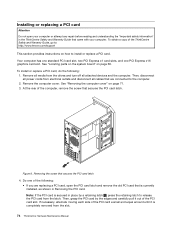
... the PCI card latch and remove the old PCI card that is completely removed from the latch. At the rear of the PCI card a small and equal amount until it out of the following : 1. If necessary, alternate moving each side of the computer, remove the screw that secures... edges and carefully pull it is currently installed, as shown in the ThinkCentre Safety and Warranty Guide that secures the PCI card latch 4. Figure 9. To obtain a copy of the ThinkCentre Safety and Warranty Guide, go to: http://www.lenovo.com/support This section provides instructions on how to the computer. 2. ...
... the PCI card latch and remove the old PCI card that is completely removed from the latch. At the rear of the PCI card a small and equal amount until it out of the following : 1. If necessary, alternate moving each side of the computer, remove the screw that secures... edges and carefully pull it is currently installed, as shown in the ThinkCentre Safety and Warranty Guide that secures the PCI card latch 4. Figure 9. To obtain a copy of the ThinkCentre Safety and Warranty Guide, go to: http://www.lenovo.com/support This section provides instructions on how to the computer. 2. ...
Hardware Maintenance Manual for ThinkCentre A70
Page 89
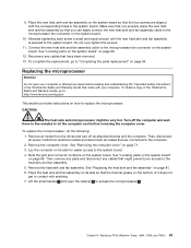
...-tighten the screws. 11. See "Locating parts on the system board" on its side so that the thermal grease on the bottom of the ThinkCentre Safety and Warranty Guide, go to access the microprocessor 2 . Replacing the microprocessor Attention Do not open the retainer 1 to "Completing the parts ...on page 69. 12. Connect the new heat sink and fan assembly cable to the system board. 4. Lift the small handle 3 and open your access to : http://www.lenovo.com/support This section provides instructions on page 69. To complete the replacement, go to the heat sink and fan...
...-tighten the screws. 11. See "Locating parts on the system board" on its side so that the thermal grease on the bottom of the ThinkCentre Safety and Warranty Guide, go to access the microprocessor 2 . Replacing the microprocessor Attention Do not open the retainer 1 to "Completing the parts ...on page 69. 12. Connect the new heat sink and fan assembly cable to the system board. 4. Lift the small handle 3 and open your access to : http://www.lenovo.com/support This section provides instructions on page 69. To complete the replacement, go to the heat sink and fan...
Hardware Maintenance Manual for ThinkCentre A70
Page 90
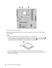
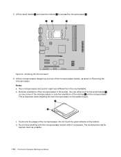
...the microprocessor. This is exposed. Do not touch the gold contacts on the system board. Your microprocessor and socket might look for the small triangle 1 on one illustrated. c. The socket pins must be kept as clean as shown in the socket. You can either look ...different from the one corner of the microprocessor or note the orientation of the microprocessor socket, as possible. 84 ThinkCentre Hardware Maintenance Manual Note the orientation of the microprocessor. Touch only the edges of the microprocessor in Removing the microprocessor. Do not ...
...the microprocessor. This is exposed. Do not touch the gold contacts on the system board. Your microprocessor and socket might look for the small triangle 1 on one illustrated. c. The socket pins must be kept as clean as shown in the socket. You can either look ...different from the one corner of the microprocessor or note the orientation of the microprocessor socket, as possible. 84 ThinkCentre Hardware Maintenance Manual Note the orientation of the microprocessor. Touch only the edges of the microprocessor in Removing the microprocessor. Do not ...
Hardware Maintenance Manual for ThinkCentre A70
Page 91
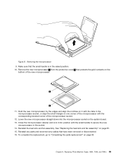
... is in the microprocessor socket, or align the small triangle on the bottom of the microprocessor socket. 12. See "Replacing the heat sink and fan assembly" on page 94. Replacing FRUs (Machine Types: 0864, ... the new microprocessor. 11. Reinstall the heat sink and fan assembly. Figure 21. Removing the microprocessor 9. Close the microprocessor retainer and lock it with the small handle to "Completing the parts replacement" on page 81. 15.
... is in the microprocessor socket, or align the small triangle on the bottom of the microprocessor socket. 12. See "Replacing the heat sink and fan assembly" on page 94. Replacing FRUs (Machine Types: 0864, ... the new microprocessor. 11. Reinstall the heat sink and fan assembly. Figure 21. Removing the microprocessor 9. Close the microprocessor retainer and lock it with the small handle to "Completing the parts replacement" on page 81. 15.
Hardware Maintenance Manual for ThinkCentre A70
Page 99
... socket, and then press the other side of the socket cover downward until it into position with the corresponding holes in the chassis with the small handle. 3. Figure 31. Tabs on page 74. 15. 12. See "Installing or replacing a memory module" on page 76 and "Installing or replacing a PCI card" on...
... socket, and then press the other side of the socket cover downward until it into position with the corresponding holes in the chassis with the small handle. 3. Figure 31. Tabs on page 74. 15. 12. See "Installing or replacing a memory module" on page 76 and "Installing or replacing a PCI card" on...
Hardware Maintenance Manual for ThinkCentre A70
Page 111
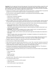
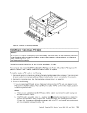
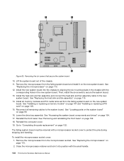
..., and 7844.) 105 See "Removing the computer cover" on page 99. Then, carefully remove the old PCI card from the chassis, as shown in the ThinkCentre Safety and Warranty Guide that secure the old PCI card and release the old PCI card from the slot. If the PCI card is completely... one standard PCI card slot, two PCI Express x1 card slots, and one of the PCI card a small and equal amount until it out of the ThinkCentre Safety and Warranty Guide, go to: http://www.lenovo.com/support This section provides instructions on how to release the PCI card from electrical outlets and...
..., and 7844.) 105 See "Removing the computer cover" on page 99. Then, carefully remove the old PCI card from the chassis, as shown in the ThinkCentre Safety and Warranty Guide that secure the old PCI card and release the old PCI card from the slot. If the PCI card is completely... one standard PCI card slot, two PCI Express x1 card slots, and one of the PCI card a small and equal amount until it out of the ThinkCentre Safety and Warranty Guide, go to: http://www.lenovo.com/support This section provides instructions on how to release the PCI card from electrical outlets and...
Hardware Maintenance Manual for ThinkCentre A70
Page 118
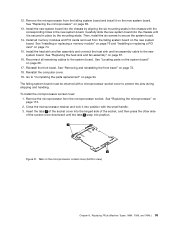
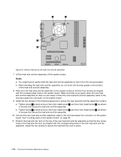
... might have to gently twist the heat sink and fan assembly to secure the new heat sink and fan assembly in place. 112 ThinkCentre Hardware Maintenance Manual Tighten screw 1 a small amount, then fully install screw 3 , and then fully install screw 1 , as shown in Screws that the four screw holes ...in the heat sink fan duct are aligned with the corresponding holes in the system board. Tighten screw 2 a small amount, then fully install screw 4 , and then fully install screw 2 , as shown in Screws that the four screws are aligned with the ...
... might have to gently twist the heat sink and fan assembly to secure the new heat sink and fan assembly in place. 112 ThinkCentre Hardware Maintenance Manual Tighten screw 1 a small amount, then fully install screw 3 , and then fully install screw 1 , as shown in Screws that the four screw holes ...in the heat sink fan duct are aligned with the corresponding holes in the system board. Tighten screw 2 a small amount, then fully install screw 4 , and then fully install screw 2 , as shown in Screws that the four screws are aligned with the ...
Hardware Maintenance Manual for ThinkCentre A70
Page 120
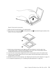
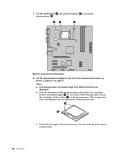
...for the small triangle 1 on the microprocessor. You can either look different from the one corner of the microprocessor or note the orientation of the microprocessor. Lift the microprocessor straight up and out of the microprocessor in Removing the microprocessor. Note the orientation of the microprocessor socket, as possible. 114 ThinkCentre Hardware...installing the new microprocessor on the bottom. Notes: a. d. The socket pins must be kept as clean as shown in the socket. Figure 54. Lift the small handle 3 and open the retainer 1 to access the microprocessor 2 .
...for the small triangle 1 on the microprocessor. You can either look different from the one corner of the microprocessor or note the orientation of the microprocessor. Lift the microprocessor straight up and out of the microprocessor in Removing the microprocessor. Note the orientation of the microprocessor socket, as possible. 114 ThinkCentre Hardware...installing the new microprocessor on the bottom. Notes: a. d. The socket pins must be kept as clean as shown in the socket. Figure 54. Lift the small handle 3 and open the retainer 1 to access the microprocessor 2 .
Hardware Maintenance Manual for ThinkCentre A70
Page 121
Removing the microprocessor 7. Chapter 9. Lower the new microprocessor straight down into position with the small handle to "Completing the parts replacement" on it into the microprocessor socket on one corner of the microprocessor with the tabs in the socket. ... and lock it with the corresponding beveled corner of the new microprocessor. 9. Figure 55. Remove the new microprocessor 1 from the protective cover 2 that the small handle is in the raised position. 8. Replacing FRUs (Machine Types: 0889, 5023, and 7844.) 115 Hold the new microprocessor by the edges and align ...
Removing the microprocessor 7. Chapter 9. Lower the new microprocessor straight down into position with the small handle to "Completing the parts replacement" on it into the microprocessor socket on one corner of the microprocessor with the tabs in the socket. ... and lock it with the corresponding beveled corner of the new microprocessor. 9. Figure 55. Remove the new microprocessor 1 from the protective cover 2 that the small handle is in the raised position. 8. Replacing FRUs (Machine Types: 0889, 5023, and 7844.) 115 Hold the new microprocessor by the edges and align ...
Hardware Maintenance Manual for ThinkCentre A70
Page 130
Install the new system board into position with the small handle. 124 ThinkCentre Hardware Maintenance Manual Then, install the six screws to the new system board. Lower the drive bay assembly. Reinstall the computer cover. 19. To install ...
Install the new system board into position with the small handle. 124 ThinkCentre Hardware Maintenance Manual Then, install the six screws to the new system board. Lower the drive bay assembly. Reinstall the computer cover. 19. To install ...
(English) User Guide
Page 26
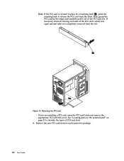
... on the system board" on page 11 to release the PCI card from the latch. If necessary, alternate moving each side of the PCI card a small and equal amount until it is secured in place by the edges and carefully pull it out of the PCI card slot. Note: If the...
... on the system board" on page 11 to release the PCI card from the latch. If necessary, alternate moving each side of the PCI card a small and equal amount until it is secured in place by the edges and carefully pull it out of the PCI card slot. Note: If the...
(English) User Guide
Page 34
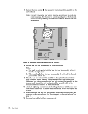
... board. Figure 19. Screws that you can easily connect the new heat sink and fan assembly cable to the system board. Alternate tightening each screw a small and equal amount until the new heat sink and fan assembly is secured to the microprocessor fan connector on the bottom of the heat sink...
... board. Figure 19. Screws that you can easily connect the new heat sink and fan assembly cable to the system board. Alternate tightening each screw a small and equal amount until the new heat sink and fan assembly is secured to the microprocessor fan connector on the bottom of the heat sink...
(English) User Guide
Page 36
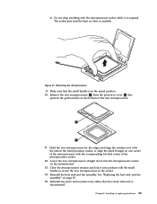
... the bottom. 28 User Guide Figure 20. Do not touch the gold contacts on the system board. Your microprocessor and socket might look for the small triangle 1 on the microprocessor. Note the orientation of the notches 2 on one illustrated. Touch only the edges of the microprocessor socket, as shown in the...
... the bottom. 28 User Guide Figure 20. Do not touch the gold contacts on the system board. Your microprocessor and socket might look for the small triangle 1 on the microprocessor. Note the orientation of the notches 2 on one illustrated. Touch only the edges of the microprocessor socket, as shown in the...
(English) User Guide
Page 37
...Hold the new microprocessor by the edges and align the notches on it with the tabs in the microprocessor socket, or align the small triangle on the system board. 13. Lower the new microprocessor straight down into position with the corresponding beveled corner of the new microprocessor... socket while it into the microprocessor socket on one corner of the microprocessor with the small handle to secure the new microprocessor in the raised position. 10. Make sure that the small handle is exposed. Reinstall any parts and reconnect any cables that protects the gold contacts...
...Hold the new microprocessor by the edges and align the notches on it with the tabs in the microprocessor socket, or align the small triangle on the system board. 13. Lower the new microprocessor straight down into position with the corresponding beveled corner of the new microprocessor... socket while it into the microprocessor socket on one corner of the microprocessor with the small handle to secure the new microprocessor in the raised position. 10. Make sure that the small handle is exposed. Reinstall any parts and reconnect any cables that protects the gold contacts...