(English) Rescue and Recovery 4.3 Deployment Guide
Page 34
... as an installation is complete: HKLM\Software\Lenovo\Rescue and Recovery\runbasebackuplocation DWord = location value BackupList: The registry entry format is how the Rescue and Recovery program knows what files have problems starting the service after the selected backup is connected to an AC power supply before the Rescue and Recovery program takes...
... as an installation is complete: HKLM\Software\Lenovo\Rescue and Recovery\runbasebackuplocation DWord = location value BackupList: The registry entry format is how the Rescue and Recovery program knows what files have problems starting the service after the selected backup is connected to an AC power supply before the Rescue and Recovery program takes...
(English) Rescue and Recovery 4.5 Deployment Guide
Page 28
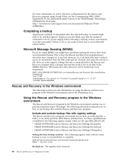
...All Internet Explorer favorites and application data do so can back them up on the ThinkVantage Technologies Administrator Tools page: http://support.lenovo.com/en_US/detail.page?LegacyDocID=TVAN-ADMIN#rnr Completing a backup Applications installed or uninstalled after a restore operation from USB or ... work because those files aren't backed up . When restoring from an incremental backup. Here are attempting to an AC power supply before the 22 Rescue and Recovery 4.5 Deployment Guide Make sure that run a command before initiating a backup, restore, rejuvenation, or ...
...All Internet Explorer favorites and application data do so can back them up on the ThinkVantage Technologies Administrator Tools page: http://support.lenovo.com/en_US/detail.page?LegacyDocID=TVAN-ADMIN#rnr Completing a backup Applications installed or uninstalled after a restore operation from USB or ... work because those files aren't backed up . When restoring from an incremental backup. Here are attempting to an AC power supply before the 22 Rescue and Recovery 4.5 Deployment Guide Make sure that run a command before initiating a backup, restore, rejuvenation, or ...
Hardware Maintenance Manual for ThinkCentre A70
Page 5
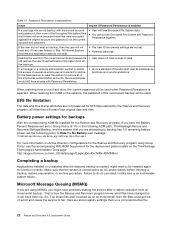
...43 Hard disk drive boot error 43 Power Supply Problems 43 Diagnostic error codes 43 Beep symptoms 61 POST error codes 62 Miscellaneous error messages 63 Undetermined problems 65 Chapter 8. Diagnostic programs . . . 35 Lenovo ThinkVantage Toolbox 35 Lenovo Solution Center 35 PC-Doctor for ... . . . 72 Installing or replacing a PCI card 74 Installing or replacing a memory module . . . . 76 Replacing the battery 78 Replacing the power supply assembly . . . . . 79 Replacing the heat sink and fan assembly . . . . 81 Replacing the microprocessor 83 Replacing the optical drive 86...
...43 Hard disk drive boot error 43 Power Supply Problems 43 Diagnostic error codes 43 Beep symptoms 61 POST error codes 62 Miscellaneous error messages 63 Undetermined problems 65 Chapter 8. Diagnostic programs . . . 35 Lenovo ThinkVantage Toolbox 35 Lenovo Solution Center 35 PC-Doctor for ... . . . 72 Installing or replacing a PCI card 74 Installing or replacing a memory module . . . . 76 Replacing the battery 78 Replacing the power supply assembly . . . . . 79 Replacing the heat sink and fan assembly . . . . 81 Replacing the microprocessor 83 Replacing the optical drive 86...
Hardware Maintenance Manual for ThinkCentre A70
Page 6
...107 Replacing the battery 109 Replacing the heat sink and fan assembly . . . . 110 Replacing the microprocessor 113 Replacing the power supply assembly . . . . . 116 Replacing the optical drive 120 Replacing the system board 123 Replacing the hard disk drive ...Overall: MT 0889, 5023, and 7844 196 Mechanical FRUs 204 Keyboard and Mouse 206 Adapters and miscellaneous FRUs 228 Power Cords 229 Recovery discs 233 Windows 7 Professional 32 Recovery CD . . 233 Windows 7 Professional 32 with MS ...conformance CE mark 260 Trademarks 260 Index 261 iv ThinkCentre Hardware Maintenance Manual
...107 Replacing the battery 109 Replacing the heat sink and fan assembly . . . . 110 Replacing the microprocessor 113 Replacing the power supply assembly . . . . . 116 Replacing the optical drive 120 Replacing the system board 123 Replacing the hard disk drive ...Overall: MT 0889, 5023, and 7844 196 Mechanical FRUs 204 Keyboard and Mouse 206 Adapters and miscellaneous FRUs 228 Power Cords 229 Recovery discs 233 Windows 7 Professional 32 Recovery CD . . 233 Windows 7 Professional 32 with MS ...conformance CE mark 260 Trademarks 260 Index 261 iv ThinkCentre Hardware Maintenance Manual
Hardware Maintenance Manual for ThinkCentre A70
Page 10
... to get medical aid. 4 ThinkCentre Hardware Maintenance Manual do not become a victim yourself. - Ensure that power has been disconnected from their equipment, rubber floor mats that has hazardous voltages. • Disconnect all power before: - Observe the special safety precautions when you start to decrease electrostatic discharges. The surface is near power supplies - Use caution; Some...
... to get medical aid. 4 ThinkCentre Hardware Maintenance Manual do not become a victim yourself. - Ensure that power has been disconnected from their equipment, rubber floor mats that has hazardous voltages. • Disconnect all power before: - Observe the special safety precautions when you start to decrease electrostatic discharges. The surface is near power supplies - Use caution; Some...

Hardware Maintenance Manual for ThinkCentre A70
Page 12
... the following languages: • English • Arabic • Brazilian/Portuguese • Chinese (simplified) • Chinese (traditional) 6 ThinkCentre Hardware Maintenance Manual Grounding requirements Electrical grounding of a grounded work mat to eliminate static on these systems. - Use good judgment as those ... You can be considered sensitive to provide protection that the machine, the part, the work surface. Make sure that the power-supply cover fasteners (screws or rivets) have been certified (ISO 9000) as metal filings, contamination, water or other people while...
... the following languages: • English • Arabic • Brazilian/Portuguese • Chinese (simplified) • Chinese (traditional) 6 ThinkCentre Hardware Maintenance Manual Grounding requirements Electrical grounding of a grounded work mat to eliminate static on these systems. - Use good judgment as those ... You can be considered sensitive to provide protection that the machine, the part, the work surface. Make sure that the power-supply cover fasteners (screws or rivets) have been certified (ISO 9000) as metal filings, contamination, water or other people while...

Hardware Maintenance Manual for ThinkCentre A70
Page 14
.... Do not stare into the beam, do not turn off the electrical current supplied to the device. CAUTION: The power control button on the device and the power switch on the power supply do not view directly with optical instruments, and avoid direct exposure to hazardous laser radiation. CAUTION: When laser products (such as CD.... DANGER Some laser products contain an embedded Class 3A or Class 3B laser diode. To remove all electrical current from the device, ensure that all power cords are disconnected from the power source. 2 1 8 ThinkCentre Hardware Maintenance Manual
.... Do not stare into the beam, do not turn off the electrical current supplied to the device. CAUTION: The power control button on the device and the power switch on the power supply do not view directly with optical instruments, and avoid direct exposure to hazardous laser radiation. CAUTION: When laser products (such as CD.... DANGER Some laser products contain an embedded Class 3A or Class 3B laser diode. To remove all electrical current from the device, ensure that all power cords are disconnected from the power source. 2 1 8 ThinkCentre Hardware Maintenance Manual

Hardware Maintenance Manual for ThinkCentre A70
Page 49
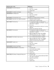
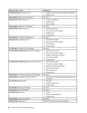
... the start -up drive is in configuration. Attempt to "Undetermined problems" on switch for information about the diagnostic programs. © Copyright Lenovo 2010, 2012 43 Symptom-to-FRU index The Symptom-to help you are needed when servicing a computer. The most likely cause is defective... possible causes. Hard disk drive boot error A hard disk drive boot error (error codes 1962 and I999030X) can use the following causes. Power Supply Problems If you get a diagnostic error code when running a test, but did not receive any error message, look for continuity. See "Running...
... the start -up drive is in configuration. Attempt to "Undetermined problems" on switch for information about the diagnostic programs. © Copyright Lenovo 2010, 2012 43 Symptom-to-FRU index The Symptom-to help you are needed when servicing a computer. The most likely cause is defective... possible causes. Hard disk drive boot error A hard disk drive boot error (error codes 1962 and I999030X) can use the following causes. Power Supply Problems If you get a diagnostic error code when running a test, but did not receive any error message, look for continuity. See "Running...
Hardware Maintenance Manual for ThinkCentre A70
Page 59
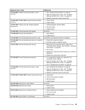
... board No action 1. IDE signal cable 2. Riser card, if installed 3. Riser card, if installed 3. See "Updating (flashing) the BIOS from a disc" on page 255 3. Check power supply voltages 3. Flash the system. Symptom-to review the log file 2. Re-run test 3. Go to reset the log file 1. Diagnostic Error Code 018-250-XXX...
... board No action 1. IDE signal cable 2. Riser card, if installed 3. Riser card, if installed 3. See "Updating (flashing) the BIOS from a disc" on page 255 3. Check power supply voltages 3. Flash the system. Symptom-to review the log file 2. Re-run test 3. Go to reset the log file 1. Diagnostic Error Code 018-250-XXX...

Hardware Maintenance Manual for ThinkCentre A70
Page 60
...is called out in warning statement 4. If a component is connected and/or enabled. Check power supply 3. IDE device 5. See "Updating (flashing) the BIOS from a disc" on page 39 2. System board Information only Re-start the test, if necessary 54 ThinkCentre Hardware Maintenance Manual Re-run test 3. See Chapter 6 "Using the Setup Utility" on...See Chapter 6 "Using the Setup Utility" on page 255 3. System board 1. SCSI device 4. Replace the component under function test No action 1. Flash the system. Check power supply 3. SCSI device 4. SCSI signal cable 2. Check...
...is called out in warning statement 4. If a component is connected and/or enabled. Check power supply 3. IDE device 5. See "Updating (flashing) the BIOS from a disc" on page 39 2. System board Information only Re-start the test, if necessary 54 ThinkCentre Hardware Maintenance Manual Re-run test 3. See Chapter 6 "Using the Setup Utility" on...See Chapter 6 "Using the Setup Utility" on page 255 3. System board 1. SCSI device 4. Replace the component under function test No action 1. Flash the system. Check power supply 3. SCSI device 4. SCSI signal cable 2. Check...
Hardware Maintenance Manual for ThinkCentre A70
Page 65
...enabled 2. Flash the system and re-test. See "Updating (flashing) the BIOS from a disc" on page 255 3. Check fans 2. Check Power supply voltages 3. System board 1. System board 1. Flash system 2. Flash the system and re-test. Diagnostic Error Code 170-199-XXX Voltage Sensor(s) ... problems" on page 39 2. See "Updating (flashing) the BIOS from a disc" on page 65 1. See "Undetermined problems" on page 255 3. Power supply 2. System board Information only Re-start the test to "Undetermined problems" on page 255 3. Re-start the test, if necessary 1. See "Updating (...
...enabled 2. Flash the system and re-test. See "Updating (flashing) the BIOS from a disc" on page 255 3. Check fans 2. Check Power supply voltages 3. System board 1. System board 1. Flash system 2. Flash the system and re-test. Diagnostic Error Code 170-199-XXX Voltage Sensor(s) ... problems" on page 39 2. See "Updating (flashing) the BIOS from a disc" on page 65 1. See "Undetermined problems" on page 255 3. Power supply 2. System board Information only Re-start the test to "Undetermined problems" on page 255 3. Re-start the test, if necessary 1. See "Updating (...
Hardware Maintenance Manual for ThinkCentre A70
Page 66
...Keyboard 2. System board No action 1. Diskette drive 4. CD-ROM drive 4. Reseat the hard disk drive cable 4. System board No action 1. Check power supply voltages 3. SCSI adapter card 6. Check and test mouse 3. Check and test Keyboard 3. Diagnostic Error Code 201-XXX-XXX System Memory error 202-... out by the test 2. Hard Disk Drive Cable 2. Check power supply voltages 3. System board No action No action 1. Hard Disk Drive Cable 2. CD-ROM Drive Cable 2. System board No action Remove the Joystick and re-test the system 60 ThinkCentre Hardware Maintenance Manual Mouse 2.
...Keyboard 2. System board No action 1. Diskette drive 4. CD-ROM drive 4. Reseat the hard disk drive cable 4. System board No action 1. Check power supply voltages 3. SCSI adapter card 6. Check and test mouse 3. Check and test Keyboard 3. Diagnostic Error Code 201-XXX-XXX System Memory error 202-... out by the test 2. Hard Disk Drive Cable 2. Check power supply voltages 3. System board No action No action 1. Hard Disk Drive Cable 2. CD-ROM Drive Cable 2. System board No action Remove the Joystick and re-test the system 60 ThinkCentre Hardware Maintenance Manual Mouse 2.

Hardware Maintenance Manual for ThinkCentre A70
Page 69
... Board 3. Network adapter (Advise network administrator of new MAC address) Dead computer. Check power supply and signal cable connections to -FRU index 63 Ensure Wake on LAN feature is properly connected to enable Wake on LAN 3. Ensure no interrupt or I/O... first device after diskette 2. Riser card, if installed Computer will not perform a Wake on page 39) 4. Ensure that network adapter is using correct MAC address 5. Power Supply 2. System Board Diskette drive in-use light remains on or does not light when drive is in Setup/Configuration (see "Starting the Setup Utility program...
... Board 3. Network adapter (Advise network administrator of new MAC address) Dead computer. Check power supply and signal cable connections to -FRU index 63 Ensure Wake on LAN feature is properly connected to enable Wake on LAN 3. Ensure no interrupt or I/O... first device after diskette 2. Riser card, if installed Computer will not perform a Wake on page 39) 4. Ensure that network adapter is using correct MAC address 5. Power Supply 2. System Board Diskette drive in-use light remains on or does not light when drive is in Setup/Configuration (see "Starting the Setup Utility program...

Hardware Maintenance Manual for ThinkCentre A70
Page 70
...1. System Board 5. network b. External Device 3. Alternate Adapter 5. System Board 2. Diskette Drive 2. System Board 3. Diskette Drive Cable 4. Power Supply RPL computer cannot access programs from left to right of characters and color bars 1. Hard disk drive RPL computer does not RPL from the...diskette drive. 1. External Device Self-Test OK? 2. System Board Some or all keys on page 43. System Board 64 ThinkCentre Hardware Maintenance Manual See "Hard disk drive boot error" on the keyboard do not work 1. Diskette Drive Cable Other display ...
...1. System Board 5. network b. External Device 3. Alternate Adapter 5. System Board 2. Diskette Drive 2. System Board 3. Diskette Drive Cable 4. Power Supply RPL computer cannot access programs from left to right of characters and color bars 1. Hard disk drive RPL computer does not RPL from the...diskette drive. 1. External Device Self-Test OK? 2. System Board Some or all keys on page 43. System Board 64 ThinkCentre Hardware Maintenance Manual See "Hard disk drive boot error" on the keyboard do not work 1. Diskette Drive Cable Other display ...
Hardware Maintenance Manual for ThinkCentre A70
Page 75
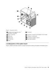
Replacing FRUs (Machine Types: 0864, 7099, and 7846.) 69 Chapter 8. Figure 3. Component locations 1 Heat sink and fan assembly (with a microprocessor underneath) 2 Memory modules (2) 3 Optical drive 4 System board 5 Hard disk drive 6 Battery 7 PCI card slot 8 PCI Express x16 graphics card (available in some models) 9 PCI Express x1 card slots (2) 10 PCI Express x16 graphics card slot 11 Power supply assembly Locating parts on the system board Figure 4 "System board part locations" on page 70 shows the locations of the parts on the system board.
Replacing FRUs (Machine Types: 0864, 7099, and 7846.) 69 Chapter 8. Figure 3. Component locations 1 Heat sink and fan assembly (with a microprocessor underneath) 2 Memory modules (2) 3 Optical drive 4 System board 5 Hard disk drive 6 Battery 7 PCI card slot 8 PCI Express x16 graphics card (available in some models) 9 PCI Express x1 card slots (2) 10 PCI Express x16 graphics card slot 11 Power supply assembly Locating parts on the system board Figure 4 "System board part locations" on page 70 shows the locations of the parts on the system board.
Hardware Maintenance Manual for ThinkCentre A70
Page 85
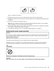
...the Setup Utility" on page 94. 9. DANGER Hazardous moving parts in the ThinkCentre Safety and Warranty Guide that has the following warnings are no moving parts. CAUTION: Never remove the cover on a power supply or any cables that have been removed or disconnected. 8. This is turned ...part that came with your safety and proper Underwriters Laboratories (UL) certification. To obtain a copy of the ThinkCentre Safety and Warranty Guide, go to : http://www.lenovo.com/support This section provides instructions on for your computer. Figure 16. Installing the new battery 7.
...the Setup Utility" on page 94. 9. DANGER Hazardous moving parts in the ThinkCentre Safety and Warranty Guide that has the following warnings are no moving parts. CAUTION: Never remove the cover on a power supply or any cables that have been removed or disconnected. 8. This is turned ...part that came with your safety and proper Underwriters Laboratories (UL) certification. To obtain a copy of the ThinkCentre Safety and Warranty Guide, go to : http://www.lenovo.com/support This section provides instructions on for your computer. Figure 16. Installing the new battery 7.

Hardware Maintenance Manual for ThinkCentre A70
Page 86
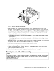
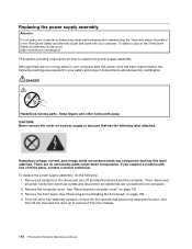
...Removing the screws that are no serviceable parts inside any component that secure the power supply assembly. Remove all media from the chassis. 80 ThinkCentre Hardware Maintenance Manual Disconnect the power supply assembly cables from all power cords from some cable clips or ties that secure the cables to the computer... that has this label attached. Then, disconnect all drives and from the 24-pin power connector and 4-pin power connector on page 69. Remove the computer cover. Slide the power supply assembly a little bit forward and then remove it from the drives and turn off ...
...Removing the screws that are no serviceable parts inside any component that secure the power supply assembly. Remove all media from the chassis. 80 ThinkCentre Hardware Maintenance Manual Disconnect the power supply assembly cables from all power cords from some cable clips or ties that secure the cables to the computer... that has this label attached. Then, disconnect all drives and from the 24-pin power connector and 4-pin power connector on page 69. Remove the computer cover. Slide the power supply assembly a little bit forward and then remove it from the drives and turn off ...
Hardware Maintenance Manual for ThinkCentre A70
Page 87
...safety information" in the ThinkCentre Safety and Warranty Guide that you set the voltage-selection switch to match the voltage available at your computer. Some power supply assemblies automatically sense the voltage or accept universal input, some power supply assemblies have a voltage-...correct replacement. Removing the power supply assembly 6. Install the new power supply assembly into the chassis so that the new power supply assembly is 200-240 V ac, set the voltage-selection switch to 230 V. 7. Note: Use only screws provided by Lenovo. 9. Replacing FRUs (Machine...
...safety information" in the ThinkCentre Safety and Warranty Guide that you set the voltage-selection switch to match the voltage available at your computer. Some power supply assemblies automatically sense the voltage or accept universal input, some power supply assemblies have a voltage-...correct replacement. Removing the power supply assembly 6. Install the new power supply assembly into the chassis so that the new power supply assembly is 200-240 V ac, set the voltage-selection switch to 230 V. 7. Note: Use only screws provided by Lenovo. 9. Replacing FRUs (Machine...

Hardware Maintenance Manual for ThinkCentre A70
Page 105
Component locations 1 Heat sink and fan assembly (with a microprocessor underneath) 2 Power supply assembly 3 Memory modules (2) 4 System board 5 Optical drive 6 the front audio and USB assembly 7 Hard disk drive 8 Battery 9 PCI Express x16 graphics card (available in some models) Locating parts on the system board Figure 37 "System board part locations" on page 100 shows the locations of the parts on the system board. Replacing FRUs (Machine Types: 0889, 5023, and 7844.) 99 Figure 36. Chapter 9.
Component locations 1 Heat sink and fan assembly (with a microprocessor underneath) 2 Power supply assembly 3 Memory modules (2) 4 System board 5 Optical drive 6 the front audio and USB assembly 7 Hard disk drive 8 Battery 9 PCI Express x16 graphics card (available in some models) Locating parts on the system board Figure 37 "System board part locations" on page 100 shows the locations of the parts on the system board. Replacing FRUs (Machine Types: 0889, 5023, and 7844.) 99 Figure 36. Chapter 9.
Hardware Maintenance Manual for ThinkCentre A70
Page 122
... cover on how to the computer. 2. DANGER Hazardous moving parts in the ThinkCentre Safety and Warranty Guide that came with one of the ThinkCentre Safety and Warranty Guide, go to: http://www.lenovo.com/support This section provides instructions on a power supply or any part that are no serviceable parts inside any repair before reading...
... cover on how to the computer. 2. DANGER Hazardous moving parts in the ThinkCentre Safety and Warranty Guide that came with one of the ThinkCentre Safety and Warranty Guide, go to: http://www.lenovo.com/support This section provides instructions on a power supply or any part that are no serviceable parts inside any repair before reading...


