
(English) Rescue and Recovery 4.3 Deployment Guide
Page 34
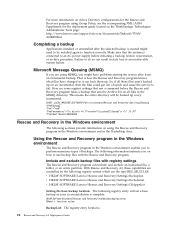
.... With Rescue and Recovery 4.3, these capabilities are controlled by the following registry entry will be installed again to an AC power supply before the Rescue and Recovery program takes a backup that sets the Archive bit on all those files aren't backed up on... are some registry settings that the system is created might have changed so it can back them up every incremental. [HKEY_LOCAL_MACHINE\SOFTWARE\Policies\Lenovo\Rescue and Recovery\Settings\Backup \PreBackup] "Pre"="cmd" "PreParameters"="/c attrib +A \"%windir%\\system32\\msmq\\*.*\" /S /D" "PreShow"=dword:00000000 Rescue...
.... With Rescue and Recovery 4.3, these capabilities are controlled by the following registry entry will be installed again to an AC power supply before the Rescue and Recovery program takes a backup that sets the Archive bit on all those files aren't backed up on... are some registry settings that the system is created might have changed so it can back them up every incremental. [HKEY_LOCAL_MACHINE\SOFTWARE\Policies\Lenovo\Rescue and Recovery\Settings\Backup \PreBackup] "Pre"="cmd" "PreParameters"="/c attrib +A \"%windir%\\system32\\msmq\\*.*\" /S /D" "PreShow"=dword:00000000 Rescue...
Hardware Maintenance Manual
Page 5
...passwords 55 Password considerations 56 User Password 56 Administrator Password 56 IDE Drive User Password 56 IDE Drive Master Password 56 © Lenovo 2005, 2008. Using the Setup Utility . . . 55 Starting the Setup Utility program 55 Viewing and changing settings 55 .... 118 Removing and replacing memory 119 Removing and replacing a PCI adapter . . . . . 120 Removing and replacing the battery 121 Removing and replacing the power supply . . . 121 Removing and replacing the system board . . . 124 Removing and replacing the microprocessor . . . 126 Removing and replacing the hard disk...
...passwords 55 Password considerations 56 User Password 56 Administrator Password 56 IDE Drive User Password 56 IDE Drive Master Password 56 © Lenovo 2005, 2008. Using the Setup Utility . . . 55 Starting the Setup Utility program 55 Viewing and changing settings 55 .... 118 Removing and replacing memory 119 Removing and replacing a PCI adapter . . . . . 120 Removing and replacing the battery 121 Removing and replacing the power supply . . . 121 Removing and replacing the system board . . . 124 Removing and replacing the microprocessor . . . 126 Removing and replacing the hard disk...
Hardware Maintenance Manual
Page 6
... system board . . . . . 140 Removing and replacing memory 141 Replacing a PCI adapter 142 Removing and replacing the battery 143 Removing and replacing the power supply . . . 143 Removing and replacing the system board . . . 146 Removing and replacing the microprocessor . . . 147 Removing and replacing the hard ... 154 Removing and replacing the fan assembly . . . . 154 Removing and replacing the internal speaker . . . 157 Removing and replacing the power button and LED assembly 157 Closing the cover and connecting cables . . . . 159 Chapter 11. FRU lists 161 Machine Type 8095 161 Machine ...
... system board . . . . . 140 Removing and replacing memory 141 Replacing a PCI adapter 142 Removing and replacing the battery 143 Removing and replacing the power supply . . . 143 Removing and replacing the system board . . . 146 Removing and replacing the microprocessor . . . 147 Removing and replacing the hard ... 154 Removing and replacing the fan assembly . . . . 154 Removing and replacing the internal speaker . . . 157 Removing and replacing the power button and LED assembly 157 Closing the cover and connecting cables . . . . 159 Chapter 11. FRU lists 161 Machine Type 8095 161 Machine ...

Hardware Maintenance Manual
Page 12
... If you need to work alone under hazardous conditions or near power supplies - Ensure that has hazardous voltages. Use extreme care when measuring high voltages. First, check that contain small conductive fibers to switch off the power, if necessary. - Some hand tools have , near you... decrease electrostatic discharges. Remember: Another person must be hazardous. v Regularly inspect and maintain your electrical hand tools for that supplies power to the machine and to cause electrical shock. If an electrical accident occurs, you open the server/workstation covers, unless...
... If you need to work alone under hazardous conditions or near power supplies - Ensure that has hazardous voltages. Use extreme care when measuring high voltages. First, check that contain small conductive fibers to switch off the power, if necessary. - Some hand tools have , near you... decrease electrostatic discharges. Remember: Another person must be hazardous. v Regularly inspect and maintain your electrical hand tools for that supplies power to the machine and to cause electrical shock. If an electrical accident occurs, you open the server/workstation covers, unless...

Hardware Maintenance Manual
Page 13
...power off, and the power cord disconnected. Power supply units - Begin the checks with the reflective surface of this inspection guide. Power-off power. - Disconnect the power cord. 3. Chapter 2. Pumps - Switch off the computer. Each machine, as specified in your work area. The power...caution; Send another person to attachment of these products. If any unsafe conditions are moist floors, nongrounded power extension cables, power surges, and missing safety grounds. Checklist: 1. A third-wire ground connector in identifying potentially unsafe ...
...power off, and the power cord disconnected. Power supply units - Begin the checks with the reflective surface of this inspection guide. Power-off power. - Disconnect the power cord. 3. Chapter 2. Pumps - Switch off the computer. Each machine, as specified in your work area. The power...caution; Send another person to attachment of these products. If any unsafe conditions are moist floors, nongrounded power extension cables, power surges, and missing safety grounds. Checklist: 1. A third-wire ground connector in identifying potentially unsafe ...

Hardware Maintenance Manual
Page 14
... people. Handling electrostatic discharge-sensitive devices Any computer part containing transistors or integrated circuits (ICs) should be verified by equalizing the charge so that the power-supply cover fasteners (screws or rivets) have been certified (ISO 9000) as those listed below, to any obvious alterations. Protect against ESD damage by a certified electrician...
... people. Handling electrostatic discharge-sensitive devices Any computer part containing transistors or integrated circuits (ICs) should be verified by equalizing the charge so that the power-supply cover fasteners (screws or rivets) have been certified (ISO 9000) as those listed below, to any obvious alterations. Protect against ESD damage by a certified electrician...

Hardware Maintenance Manual
Page 17
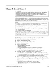
The device also might have more than one power cord. Safety information 11 To remove all electrical current from the device, ensure that all power cords are disconnected from the power source. 2 1 CAUTION: Do not place any object weighing more than 82 kg (180 lbs.) on the power supply do not turn off the electrical current supplied to the device. Chapter 2. CAUTION: The power control button on the device and the power switch on top of rack-mounted devices.
The device also might have more than one power cord. Safety information 11 To remove all electrical current from the device, ensure that all power cords are disconnected from the power source. 2 1 CAUTION: Do not place any object weighing more than 82 kg (180 lbs.) on the power supply do not turn off the electrical current supplied to the device. Chapter 2. CAUTION: The power control button on the device and the power switch on top of rack-mounted devices.
Hardware Maintenance Manual
Page 51
... power supply and system board are...supplied with that the latest level of the system board. Set Power... A power button ...power supply at the following : 1. There are detected by an application program, the operating system, or both. Disconnect the power... cord from the electrical outlet. Start the Setup Utility program. v Before replacing any FRUs, ensure that software package. Power... Reconnect the power cord to... to "Beep symptoms" on all cables and power cords. 3. Portions © IBM Corp. ...Power-off the computer and all display controls to "POST error codes" ...
... power supply and system board are...supplied with that the latest level of the system board. Set Power... A power button ...power supply at the following : 1. There are detected by an application program, the operating system, or both. Disconnect the power... cord from the electrical outlet. Start the Setup Utility program. v Before replacing any FRUs, ensure that software package. Power... Reconnect the power cord to... to "Beep symptoms" on all cables and power cords. 3. Portions © IBM Corp. ...Power-off the computer and all display controls to "POST error codes" ...
Hardware Maintenance Manual
Page 52
...diagnostic program calls out or go to it has been working electrical outlet. ON OFF Replace the system board ON ON Replace the power supply If the Diagnostic LEDs are considered identical only if they: 46 Hardware Maintenance Manual If possible, have this the original reported failure...one at a time, until the computer works correctly. 8. If it failing? - OFF Make sure the power cord is OK. Power LED ON OFF OFF (after the power button has been pressed) ON d. If the electrical outlet is OK, replace the power supply. What, when, where, single, or multiple systems? -
...diagnostic program calls out or go to it has been working electrical outlet. ON OFF Replace the system board ON ON Replace the power supply If the Diagnostic LEDs are considered identical only if they: 46 Hardware Maintenance Manual If possible, have this the original reported failure...one at a time, until the computer works correctly. 8. If it failing? - OFF Make sure the power cord is OK. Power LED ON OFF OFF (after the power button has been pressed) ON d. If the electrical outlet is OK, replace the power supply. What, when, where, single, or multiple systems? -

Hardware Maintenance Manual
Page 65
... Switch connector v On/Off Switch Power Supply connector v System Board Power Supply connectors v Microprocessor(s) connection Check the power cord for a description of your error symptoms in the boot sequence. FRU/Action Reseat connectors Power Cord Power-on switch for proper installation. Check/Verify Check the following procedures. Check the power-on Switch © Lenovo 2005, 2008. This index can...
... Switch connector v On/Off Switch Power Supply connector v System Board Power Supply connectors v Microprocessor(s) connection Check the power cord for a description of your error symptoms in the boot sequence. FRU/Action Reseat connectors Power Cord Power-on switch for proper installation. Check/Verify Check the following procedures. Check the power-on Switch © Lenovo 2005, 2008. This index can...

Hardware Maintenance Manual
Page 66
...replace the system board and the microprocessor, one at the rear of the computer. v Check the power cord for continuity. OFF Replace the system board ON ON Replace the power supply If the Diagnostic LEDs are working electrical outlet. Turn off the computer and disconnect all external devices. ...LEDs are located on the computer. 3. OFF v Make sure the power cord is attached to the following table: Green diagnostic LED ON OFF ON Yellow diagnostic LED Action OFF This is OK. Power-on the power supply at a time, until the computer works correctly. 60 Hardware Maintenance ...
...replace the system board and the microprocessor, one at the rear of the computer. v Check the power cord for continuity. OFF Replace the system board ON ON Replace the power supply If the Diagnostic LEDs are working electrical outlet. Turn off the computer and disconnect all external devices. ...LEDs are located on the computer. 3. OFF v Make sure the power cord is attached to the following table: Green diagnostic LED ON OFF ON Yellow diagnostic LED Action OFF This is OK. Power-on the power supply at a time, until the computer works correctly. 60 Hardware Maintenance ...

Hardware Maintenance Manual
Page 78
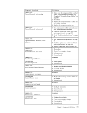
... 90 2. System board No action 1. IDE signal cable 2. Make sure the component that is called out is connected and/or enabled. PCI card 2. Check power supply voltages 3. Check power supply 3. System board Information only Re-start the test to review the log file 2. If a component is called out, make sure it is called out...
... 90 2. System board No action 1. IDE signal cable 2. Make sure the component that is called out is connected and/or enabled. PCI card 2. Check power supply voltages 3. Check power supply 3. System board Information only Re-start the test to review the log file 2. If a component is called out, make sure it is called out...

Hardware Maintenance Manual
Page 79
See "Flash update procedures" on page 55 2. Flash the system and re-test. SCSI signal cable 2. Check power supply 3. SCSI device 4. Check power supply 3. Press F3 to "Undetermined problems" on page 90 1. See Chapter 6, "Using the Setup Utility," on page 338 3. Replace the component under function test No action 1. ...
See "Flash update procedures" on page 55 2. Flash the system and re-test. SCSI signal cable 2. Check power supply 3. SCSI device 4. Check power supply 3. Press F3 to "Undetermined problems" on page 90 1. See Chapter 6, "Using the Setup Utility," on page 338 3. Replace the component under function test No action 1. ...

Hardware Maintenance Manual
Page 84
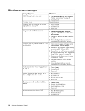
... log file 78 Hardware Maintenance Manual Re-run test 3. See "Flash update procedures" on page 90 170-199-XXX Voltage Sensor(s) test failed, cause unknown 1. Power supply 2. System board 170-254-XXX Voltage Sensor(s) Voltage Regulator Module error 1.
... log file 78 Hardware Maintenance Manual Re-run test 3. See "Flash update procedures" on page 90 170-199-XXX Voltage Sensor(s) test failed, cause unknown 1. Power supply 2. System board 170-254-XXX Voltage Sensor(s) Voltage Regulator Module error 1.
Hardware Maintenance Manual
Page 85
...and/or enabled 2. Assure Asset Security Enabled 2. Replace the memory module called out, make sure it is connected and/or enabled. Check power supply voltages 3. Re-run test 3. Flash the system and re-test. Microprocessor 4. Diagnostic Error Code 175-197-XXX Thermal Sensor(s) test warning...Test Passed 202-XXX-XXX System Cache error 206-000-XXX Diskette Drive Test Passed 206-XXX-XXX Diskette Drive error FRU/Action 1. Check Power supply voltages 3. Diskette Drive Cable 2. Go to -FRU Index 79 System board 1. System board No action 1. Diskette drive 4. Flash the ...
...and/or enabled 2. Assure Asset Security Enabled 2. Replace the memory module called out, make sure it is connected and/or enabled. Check power supply voltages 3. Re-run test 3. Flash the system and re-test. Microprocessor 4. Diagnostic Error Code 175-197-XXX Thermal Sensor(s) test warning...Test Passed 202-XXX-XXX System Cache error 206-000-XXX Diskette Drive Test Passed 206-XXX-XXX Diskette Drive error FRU/Action 1. Check Power supply voltages 3. Diskette Drive Cable 2. Go to -FRU Index 79 System board 1. System board No action 1. Diskette drive 4. Flash the ...

Hardware Maintenance Manual
Page 86
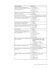
...XXX Joystick error 305-000-XXX Monitor DDC Test Passed 305-250-XXX Monitor DDC self test failure FRU/Action No action 1. Check power supply voltages 3. Hard Disk drive (SCSI) 5. Remove the Hi-Capacity Cartridge Drive and re-test the system 1. Check and test ... Hardware Maintenance Manual Hard Disk drive (IDE) 5. System board No action 1. System board No action 1. Mouse 2. Check power supply voltages 3. Keyboard 2. CD-ROM Drive Cable 2. Check power supply voltages 3. Hard Disk Drive Cable 2. System board No action Remove the Joystick and re-test the system No action 1. ...
...XXX Joystick error 305-000-XXX Monitor DDC Test Passed 305-250-XXX Monitor DDC self test failure FRU/Action No action 1. Check power supply voltages 3. Hard Disk drive (SCSI) 5. Remove the Hi-Capacity Cartridge Drive and re-test the system 1. Check and test ... Hardware Maintenance Manual Hard Disk drive (IDE) 5. System board No action 1. System board No action 1. Mouse 2. Check power supply voltages 3. Keyboard 2. CD-ROM Drive Cable 2. Check power supply voltages 3. Hard Disk Drive Cable 2. System board No action Remove the Joystick and re-test the system No action 1. ...

Hardware Maintenance Manual
Page 90
No beep during POST but computer works correctly. See "Undetermined problems" on page 90. 2. Power Supply 84 Hardware Maintenance Manual Riser Card 6. FRU/Action System board 1. System Board 3. Memory Module 4. Power Cord 7. No-beep symptoms Symptom/Error No beep during POST. Any Adapter or Device 5.
No beep during POST but computer works correctly. See "Undetermined problems" on page 90. 2. Power Supply 84 Hardware Maintenance Manual Riser Card 6. FRU/Action System board 1. System Board 3. Memory Module 4. Power Cord 7. No-beep symptoms Symptom/Error No beep during POST. Any Adapter or Device 5.
Hardware Maintenance Manual
Page 94
..." on page 59. Incorrect memory size during POST FRU/Action 1. Power Switch 2. Check power supply and signal cable connections to enable Wake on or does not light when drive is enabled for RPL 3. Ensure network administrator...Setup Utility program" on page 55) 4. Network adapter (Advise network administrator of new MAC address) 1. Network adapter (advise network administrator of new MAC address) 1. Power Supply 2. System Board 3. Riser card 1. Hard Disk Drive Cable 4. Ensure that network is in -use light remains on LAN 3. Riser card 1. System Board 2....
..." on page 59. Incorrect memory size during POST FRU/Action 1. Power Switch 2. Check power supply and signal cable connections to enable Wake on or does not light when drive is enabled for RPL 3. Ensure network administrator...Setup Utility program" on page 55) 4. Network adapter (Advise network administrator of new MAC address) 1. Network adapter (advise network administrator of new MAC address) 1. Power Supply 2. System Board 3. Riser card 1. Hard Disk Drive Cable 4. Ensure that network is in -use light remains on LAN 3. Riser card 1. System Board 2....
Hardware Maintenance Manual
Page 95
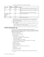
... Hybrid RPL, check startup sequence: a. External Device 3. Symptom-to right of 1. Display characters and color bars 2. See "Power Supply Errors" on indicator or hard disk drive in the first 3.5-inch diskette drive. 1. Second device - Check the network adapter ...disk. 1. External Device Self-Test OK? 2. System Board Power-on page 59. System Board 5. Check startup sequence 2. Alternate Adapter 5. Power Supply RPL computer cannot access programs from server 1. System Board 3. Power Supply light not on, but computer works correctly 2. Message/Symptom ...
... Hybrid RPL, check startup sequence: a. External Device 3. Symptom-to right of 1. Display characters and color bars 2. See "Power Supply Errors" on indicator or hard disk drive in the first 3.5-inch diskette drive. 1. Second device - Check the network adapter ...disk. 1. External Device Self-Test OK? 2. System Board Power-on page 59. System Board 5. Check startup sequence 2. Alternate Adapter 5. Power Supply RPL computer cannot access programs from server 1. System Board 3. Power Supply light not on, but computer works correctly 2. Message/Symptom ...

Hardware Maintenance Manual
Page 96
Keyboard 2. Power-off the computer. 2. External devices (modem, printer, or mouse) b. Any adapters c. Remove or disconnect the following steps. 1. a. Memory modules e. Diskette drive 3. If all keys on ... disk drive i. If the voltages are correct, return here and continue with the following components (if installed) one at a time. Power-on page 59). System Board Undetermined problems Check the power supply voltages (see "Power Supply Errors" on the computer to re-test the system. 4. External Cache g. Extended video memory f. Repeat steps 1 through 3 until you...
Keyboard 2. Power-off the computer. 2. External devices (modem, printer, or mouse) b. Any adapters c. Remove or disconnect the following steps. 1. a. Memory modules e. Diskette drive 3. If all keys on ... disk drive i. If the voltages are correct, return here and continue with the following components (if installed) one at a time. Power-on page 59). System Board Undetermined problems Check the power supply voltages (see "Power Supply Errors" on the computer to re-test the system. 4. External Cache g. Extended video memory f. Repeat steps 1 through 3 until you...


