Hardware Maintenance Manual
Page 5
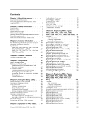
... FRUs (Types 7258, 7260, 7268, 7270, 7280, 7296, 7298, 7304, 7307,7413, 7491, and 7508) . 81 Locations 82 Rear connectors 82 Computer components 83 System board connectors 84 Removing the computer cover 85 Removing and installing the front bezel . . . . . 87 Replacing the power supply assembly . . . . ....7259, 7267, 7269, 7279, 7297, 7303, 7306, 7487, 7506, and 7514 40 Chapter 4. Symptom-to-FRU Index . . . 53 © Lenovo 2005, 2008. Contents Chapter 1. Using the Setup Utility . . . 49 Starting the Setup Utility program 49 Viewing and changing settings 49 Using passwords 49 ...
... FRUs (Types 7258, 7260, 7268, 7270, 7280, 7296, 7298, 7304, 7307,7413, 7491, and 7508) . 81 Locations 82 Rear connectors 82 Computer components 83 System board connectors 84 Removing the computer cover 85 Removing and installing the front bezel . . . . . 87 Replacing the power supply assembly . . . . ....7259, 7267, 7269, 7279, 7297, 7303, 7306, 7487, 7506, and 7514 40 Chapter 4. Symptom-to-FRU Index . . . 53 © Lenovo 2005, 2008. Contents Chapter 1. Using the Setup Utility . . . 49 Starting the Setup Utility program 49 Viewing and changing settings 49 Using passwords 49 ...

Hardware Maintenance Manual
Page 10
... the following rules when working with the power-off position. If an electrical accident occurs, you . v Regularly inspect and maintain your back. Important: Use only approved tools and test equipment. Some hand tools have , near power supplies - v Do not work on electrical ...equipment; Working near their equipment, rubber floor mats that power has been disconnected from a circuit. Ensure that supplies power to the machine and to work alone under hazardous conditions...
... the following rules when working with the power-off position. If an electrical accident occurs, you . v Regularly inspect and maintain your back. Important: Use only approved tools and test equipment. Some hand tools have , near power supplies - v Do not work on electrical ...equipment; Working near their equipment, rubber floor mats that power has been disconnected from a circuit. Ensure that supplies power to the machine and to work alone under hazardous conditions...

Hardware Maintenance Manual
Page 11
v Do not touch live electrical circuits with a voltage-selection switch located near the power-cord connection point on the computer. Pumps - Send another country, be used to identify potential safety hazards due to attachment of ...provided in your electrical outlet. Safety inspection guide The intent of the following parts with the power on these hazards are moist floors, nongrounded power extension cables, power surges, and missing safety grounds. Power supply units - Switch off power. - If your computer has a voltage-selection switch, ensure that you set to an ...
v Do not touch live electrical circuits with a voltage-selection switch located near the power-cord connection point on the computer. Pumps - Send another country, be used to identify potential safety hazards due to attachment of ...provided in your electrical outlet. Safety inspection guide The intent of the following parts with the power on these hazards are moist floors, nongrounded power extension cables, power surges, and missing safety grounds. Power supply units - Switch off power. - If your computer has a voltage-selection switch, ensure that you set to an ...
Hardware Maintenance Manual
Page 12
... hardware The guide consists of a series of steps presented in charge between the external ground pin and frame ground. Power-off , and the power cord disconnected. c. Handling electrostatic discharge-sensitive devices Any computer part containing transistors or integrated circuits (ICs) should be the...they exceed the requirements noted here. 2. v Wear a grounded wrist strap against ESD damage by equalizing the charge so that the power-supply cover fasteners (screws or rivets) have been certified (ISO 9000) as to eliminate static on the frame can continue without first ...
... hardware The guide consists of a series of steps presented in charge between the external ground pin and frame ground. Power-off , and the power cord disconnected. c. Handling electrostatic discharge-sensitive devices Any computer part containing transistors or integrated circuits (ICs) should be the...they exceed the requirements noted here. 2. v Wear a grounded wrist strap against ESD damage by equalizing the charge so that the power-supply cover fasteners (screws or rivets) have been certified (ISO 9000) as to eliminate static on the frame can continue without first ...

Hardware Maintenance Manual
Page 16
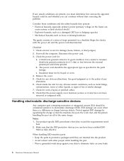
To remove all electrical current from the device, ensure that all power cords are disconnected from the power source. 2 1 10 Hardware Maintenance Manual The device also might have more than one power cord. CAUTION: The power control button on the device and the power switch on the power supply do not turn off the electrical current supplied to the device.
To remove all electrical current from the device, ensure that all power cords are disconnected from the power source. 2 1 10 Hardware Maintenance Manual The device also might have more than one power cord. CAUTION: The power control button on the device and the power switch on the power supply do not turn off the electrical current supplied to the device.

Hardware Maintenance Manual
Page 59
... index. v If you decide which FRUs to "Undetermined problems" on the start -up the data on Switch © Lenovo 2005, 2008. This index can have both an error message and an incorrect audio response, diagnose the error message first. ...available when servicing a computer. Install an operating system on switch for continuity. v Power Cord v On/Off Switch connector v On/Off Switch Power Supply connector v System Board Power Supply connectors v Microprocessor(s) connection Check the power cord for continuity. Portions © IBM Corp. 2005. 53 Chapter 7. The ...
... index. v If you decide which FRUs to "Undetermined problems" on the start -up the data on Switch © Lenovo 2005, 2008. This index can have both an error message and an incorrect audio response, diagnose the error message first. ...available when servicing a computer. Install an operating system on switch for continuity. v Power Cord v On/Off Switch connector v On/Off Switch Power Supply connector v System Board Power Supply connectors v Microprocessor(s) connection Check the power cord for continuity. Portions © IBM Corp. 2005. 53 Chapter 7. The ...
Hardware Maintenance Manual
Page 71
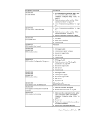
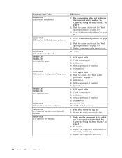
If a component is called out is connected and/or enabled. Check power supply voltages 3. IDE signal cable 2. Check power supply 3. Symptom-to "Undetermined problems" on page 79 1. Flash the system and re-test. See "Flash update procedures" on page 379 3. System board No action 1. IDE ...
If a component is called out is connected and/or enabled. Check power supply voltages 3. IDE signal cable 2. Check power supply 3. Symptom-to "Undetermined problems" on page 79 1. Flash the system and re-test. See "Flash update procedures" on page 379 3. System board No action 1. IDE ...
Hardware Maintenance Manual
Page 72
...-test. Flash the system and re-test. See "Flash update procedures" on page 49 2. SCSI device 4. SCSI signal cable 2. Check power supply 3. Press F3 to reset the log file 1. Diagnostic Error Code 025-198-XXX IDE interface test aborted 025-199-XXX IDE interface test failed...interface Test aborted by user 030-196-XXX SCSI interface test halt, error threshold exceeded 030-197-XXX SCSI interface test warning FRU/Action 1. Check power supply 3. See "Flash update procedures" on page 79 1. SCSI device 4. SCSI device 4. Re-start the test, if necessary 1. Go to "Undetermined...
...-test. Flash the system and re-test. See "Flash update procedures" on page 49 2. SCSI device 4. SCSI signal cable 2. Check power supply 3. Press F3 to reset the log file 1. Diagnostic Error Code 025-198-XXX IDE interface test aborted 025-199-XXX IDE interface test failed...interface Test aborted by user 030-196-XXX SCSI interface test halt, error threshold exceeded 030-197-XXX SCSI interface test warning FRU/Action 1. Check power supply 3. See "Flash update procedures" on page 79 1. SCSI device 4. SCSI device 4. Re-start the test, if necessary 1. Go to "Undetermined...
Hardware Maintenance Manual
Page 77
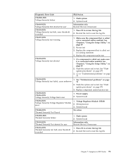
... user Information only Re-start the test, if necessary 170-196-XXX Voltage Sensor(s) test halt, error threshold exceeded 1. Flash the system and re-test. Power supply 2. System board 175-195-XXX Thermal Sensor(s) Test aborted by user Information only Re-start the test, if necessary 175-196-XXX Thermal Sensor(s) test...
... user Information only Re-start the test, if necessary 170-196-XXX Voltage Sensor(s) test halt, error threshold exceeded 1. Flash the system and re-test. Power supply 2. System board 175-195-XXX Thermal Sensor(s) Test aborted by user Information only Re-start the test, if necessary 175-196-XXX Thermal Sensor(s) test...

Hardware Maintenance Manual
Page 78
... procedures" on page 379 3. System board 3. Make sure the component that is connected and/or enabled. Replace the component under function test 1. Check power supply voltages 3. System board No action 1. Cache, if removable 2. Check Power supply voltages 3. See Chapter 6, "Using the Setup Utility," on page 49 2. If a component is called out by the test 2.
... procedures" on page 379 3. System board 3. Make sure the component that is connected and/or enabled. Replace the component under function test 1. Check power supply voltages 3. System board No action 1. Cache, if removable 2. Check Power supply voltages 3. See Chapter 6, "Using the Setup Utility," on page 49 2. If a component is called out by the test 2.

Hardware Maintenance Manual
Page 79
... and test Keyboard 3. Cable 3. Symptom-to enable DDC 2. Reseat the hard disk drive cable 4. Check power supply voltages 3. SCSI adapter card 6. Run Setup to -FRU Index 73 Mouse 2. CD-ROM Drive Cable 2. Check power supply voltages 3. Monitor 4. Check power supply voltages 3. Hard Disk Drive Cable 2. Video card 5. CD-ROM drive 4. System board No action Remove the...
... and test Keyboard 3. Cable 3. Symptom-to enable DDC 2. Reseat the hard disk drive cable 4. Check power supply voltages 3. SCSI adapter card 6. Run Setup to -FRU Index 73 Mouse 2. CD-ROM Drive Cable 2. Check power supply voltages 3. Monitor 4. Check power supply voltages 3. Hard Disk Drive Cable 2. Video card 5. CD-ROM drive 4. System board No action Remove the...
Hardware Maintenance Manual
Page 84
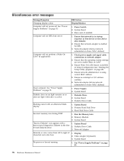
...network administrator is active. Network adapter (advise network administrator of new MAC address) 1. Power Supply 2. Diskette Drive Cable 1. Memory Module 3. Network Adapter 1. Display 2. Computer will not power-off. Diskette Drive 2. Diskette Drive Cable 3. Diskette drive in the first 3.5-inch ... Primary Hard Disk Drive 3. Run the Memory tests 2. See "Power Supply Problems" on page 53. 78 Hardware Maintenance Manual Hard Disk Drive Cable 1. System Board 2. See "Power Supply Problems" on page 53. Miscellaneous error messages Message/Symptom Changing display ...
...network administrator is active. Network adapter (advise network administrator of new MAC address) 1. Power Supply 2. Diskette Drive Cable 1. Memory Module 3. Network Adapter 1. Display 2. Computer will not power-off. Diskette Drive 2. Diskette Drive Cable 3. Diskette drive in the first 3.5-inch ... Primary Hard Disk Drive 3. Run the Memory tests 2. See "Power Supply Problems" on page 53. 78 Hardware Maintenance Manual Hard Disk Drive Cable 1. System Board 2. See "Power Supply Problems" on page 53. Miscellaneous error messages Message/Symptom Changing display ...
Hardware Maintenance Manual
Page 85
...System Board Serial or parallel port device failure (adapter port) 1. External Device 3. a. Symptom-to-FRU Index 79 Diskette Drive 2. Power Supply RPL computer cannot access programs from server 1. hard disk 2. External Device Self-Test OK? 2. Alternate Adapter 5. System Board Program loads...disk. 1. Check startup sequence 2. Check the network adapter LED status Serial or parallel port device failure (system board port) 1. Power-off the computer. 2. Any adapters Chapter 7. System Board 3. Diskette Drive Cable Other display symptoms not listed above (including blank...
...System Board Serial or parallel port device failure (adapter port) 1. External Device 3. a. Symptom-to-FRU Index 79 Diskette Drive 2. Power Supply RPL computer cannot access programs from server 1. hard disk 2. External Device Self-Test OK? 2. Alternate Adapter 5. System Board Program loads...disk. 1. Check startup sequence 2. Check the network adapter LED status Serial or parallel port device failure (system board port) 1. Power-off the computer. 2. Any adapters Chapter 7. System Board 3. Diskette Drive Cable Other display symptoms not listed above (including blank...

Hardware Maintenance Manual
Page 89
Replacing FRUs - Tamdhu Computers 83 Computer components The following illustration will help you locate the major FRUs in the computer. 1 Heat sink, and fan assembly 2 Microprocessor 3 Memory 4 Optical drive 5 Diskette drive 6 Power switch / LED assembly 7 Internal speaker 8 Front audio / USB assembly 9 Hard disk drive 10 System board 11 Rear system fan 12 Power supply Chapter 8.
Replacing FRUs - Tamdhu Computers 83 Computer components The following illustration will help you locate the major FRUs in the computer. 1 Heat sink, and fan assembly 2 Microprocessor 3 Memory 4 Optical drive 5 Diskette drive 6 Power switch / LED assembly 7 Internal speaker 8 Front audio / USB assembly 9 Hard disk drive 10 System board 11 Rear system fan 12 Power supply Chapter 8.

Hardware Maintenance Manual
Page 94
... components. Lay the computer on how to : http://www.lenovo.com/support This section provides instructions on its side. 3. To replace the power supply assembly: 1. Attention Do not open your computer. To obtain a copy of the ThinkCentre Safety and Warranty Guide, go to replace the power supply assembly. Remove the computer cover. See "Removing the computer...
... components. Lay the computer on how to : http://www.lenovo.com/support This section provides instructions on its side. 3. To replace the power supply assembly: 1. Attention Do not open your computer. To obtain a copy of the ThinkCentre Safety and Warranty Guide, go to replace the power supply assembly. Remove the computer cover. See "Removing the computer...

Hardware Maintenance Manual
Page 95
... a different position. Lift the power supply assembly out of the chassis that the new power supply assembly is the correct replacement. If necessary, use a ballpoint pen to slide the switch to secure the power supply. Note: Use only the screws provided by Lenovo. 9. Go to the system... board and the drives. 10. Tamdhu Computers 89 Reconnect the power supply cables to "Completing the FRU replacement" on page 120. 4. If your power supply assembly has a voltage-...
... a different position. Lift the power supply assembly out of the chassis that the new power supply assembly is the correct replacement. If necessary, use a ballpoint pen to slide the switch to secure the power supply. Note: Use only the screws provided by Lenovo. 9. Go to the system... board and the drives. 10. Tamdhu Computers 89 Reconnect the power supply cables to "Completing the FRU replacement" on page 120. 4. If your power supply assembly has a voltage-...

Hardware Maintenance Manual
Page 129
Computer components The following illustration will help you locate the major FRUs in the computer. 1 Hard disk drive 2 Microprocessor, heat sink and fan assembly 3 Internal speaker (some models) 4 Optical drive 5 Memory slots (2) 6 Power supply assembly Chapter 9. Replacing FRUs - 607 computers 123
Computer components The following illustration will help you locate the major FRUs in the computer. 1 Hard disk drive 2 Microprocessor, heat sink and fan assembly 3 Internal speaker (some models) 4 Optical drive 5 Memory slots (2) 6 Power supply assembly Chapter 9. Replacing FRUs - 607 computers 123

Hardware Maintenance Manual
Page 135
... the power supply assembly. Replacing the power supply Attention Do not open your computer. Pivot the drive bay assembly upward to gain access to : http://www.lenovo.com/support Attention Never remove the cover on page 125. 3. Chapter 9. Remove the four screws at the rear of the ThinkCentre Safety and Warranty Guide, go to the power supply assembly...
... the power supply assembly. Replacing the power supply Attention Do not open your computer. Pivot the drive bay assembly upward to gain access to : http://www.lenovo.com/support Attention Never remove the cover on page 125. 3. Chapter 9. Remove the four screws at the rear of the ThinkCentre Safety and Warranty Guide, go to the power supply assembly...

Hardware Maintenance Manual
Page 136
...cables from the computer. 8. Install the new power supply assembly into the chassis so that the screw holes in the new power supply assembly align with those in the chassis. 9. Go to secure the power supply assembly. Slide the power supply assembly away from the chassis and remove it ... replacement" on page 150. 130 Hardware Maintenance Manual Reconnect all drives and from the power connectors. 6. 5. Note: Use only the screws provided by Lenovo. 10. Disconnect the power supply assembly cables from all the power supply assembly cables to the drives and the system board. 11.
...cables from the computer. 8. Install the new power supply assembly into the chassis so that the screw holes in the new power supply assembly align with those in the chassis. 9. Go to secure the power supply assembly. Slide the power supply assembly away from the chassis and remove it ... replacement" on page 150. 130 Hardware Maintenance Manual Reconnect all drives and from the power connectors. 6. 5. Note: Use only the screws provided by Lenovo. 10. Disconnect the power supply assembly cables from all the power supply assembly cables to the drives and the system board. 11.
Hardware Maintenance Manual
Page 156
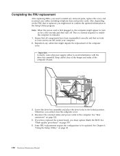
...all components have replaced the system board, you must update (flash) the BIOS. Ensure that all power supply cables to avoid interference with the drive bay assembly. Note: When the power cord is a normal sequence to enable the computer to initialize. 1. Some FRU replacements require the configuration... FRU that is replaced, you cannot close the computer cover. 4. Also, depending on page 379. 6. Reconnect the external cables and power cords to confirm the updated information in , the computer might need to install any removed parts, replace the cover, and reconnect any ...
...all components have replaced the system board, you must update (flash) the BIOS. Ensure that all power supply cables to avoid interference with the drive bay assembly. Note: When the power cord is a normal sequence to enable the computer to initialize. 1. Some FRU replacements require the configuration... FRU that is replaced, you cannot close the computer cover. 4. Also, depending on page 379. 6. Reconnect the external cables and power cords to confirm the updated information in , the computer might need to install any removed parts, replace the cover, and reconnect any ...


