
K200 Hardware Maintenance Manual
Page 3
...sure to read the Safety Information. It is invalid for trained servicers who are also available at: http:/www.lenovo.com/support. This manual includes a complete FRU part number listing for Lenovo IdeaCentre K computers listed on the cover. Lesen Sie unbedingt alle Hinweise vom Typ "ACHTUNG" oder "VORSICHT" in... for each machine type and model listed on the cover. If you have internet access, FRU part numbers are familiar with Lenovo computer products. Veuillez lire toutes les consignes de type DANGER et ATTENTION du présent document avant d'exécuter les instructions...
...sure to read the Safety Information. It is invalid for trained servicers who are also available at: http:/www.lenovo.com/support. This manual includes a complete FRU part number listing for Lenovo IdeaCentre K computers listed on the cover. Lesen Sie unbedingt alle Hinweise vom Typ "ACHTUNG" oder "VORSICHT" in... for each machine type and model listed on the cover. If you have internet access, FRU part numbers are familiar with Lenovo computer products. Veuillez lire toutes les consignes de type DANGER et ATTENTION du présent document avant d'exécuter les instructions...

K200 Hardware Maintenance Manual
Page 5
RoHS compliant Lenovo IdeaCentre K parts have unique FRU part numbers. Related Web URLs are: •• Lenovo information for Suppliers website: http://www-03.ibm.com/procurement/proweb.nsf/ ContentDocsByTitle/United+States~Information+for those FRUs can be replaced using RoHS compliant ... RoHS Must be RoHS Non-RoHS Can be RoHS Non-RoHS Can sub to RoHS RoHS Must be ready to these products and any product Lenovo produces containing RoHS compliant parts. The following statement pertains to support...
RoHS compliant Lenovo IdeaCentre K parts have unique FRU part numbers. Related Web URLs are: •• Lenovo information for Suppliers website: http://www-03.ibm.com/procurement/proweb.nsf/ ContentDocsByTitle/United+States~Information+for those FRUs can be replaced using RoHS compliant ... RoHS Must be RoHS Non-RoHS Can be RoHS Non-RoHS Can sub to RoHS RoHS Must be ready to these products and any product Lenovo produces containing RoHS compliant parts. The following statement pertains to support...

K200 Hardware Maintenance Manual
Page 14
...; to 55°C Humidity: Operating: 35% to 80% Transit: 20% to 93% (40°C) Altitude: 86KPa to all machine types supported by this publication. Type Lenovo IdeaCentre K This section lists the physical specifications. Hardware Maintenance Manual General information 3 This chapter provides general information that applies to 106KPa Electrical input Input voltage: 220V...
...; to 55°C Humidity: Operating: 35% to 80% Transit: 20% to 93% (40°C) Altitude: 86KPa to all machine types supported by this publication. Type Lenovo IdeaCentre K This section lists the physical specifications. Hardware Maintenance Manual General information 3 This chapter provides general information that applies to 106KPa Electrical input Input voltage: 220V...

K210 Hardware Replacement Guide
Page 3
... the system fan assembly 23 Replacing the keyboard 25 Replacing the mouse 26 Replacing the External speaker 27 Completing the installation 27 Appendix 29 31032753 IdeaCentre K_HRG_EN.indd 32 2007.12.11 9:13:40 AM
... the system fan assembly 23 Replacing the keyboard 25 Replacing the mouse 26 Replacing the External speaker 27 Completing the installation 27 Appendix 29 31032753 IdeaCentre K_HRG_EN.indd 32 2007.12.11 9:13:40 AM
K210 Hardware Replacement Guide
Page 4
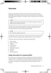
.... Overview This guide is intended to be referred to the Hardware Maintenance Manual (HMM) for all parts. Hardware Replacement Guide 1 31032753 IdeaCentre K_HRG_EN.indd 1 2007.12.10 3:53:07 PM It is expected that was included with your computer or attempt any repair before reading... Guide that cables, switches, and certain mechanical parts can obtain one online from the Support Web site at http://www.lenovo.com/ support. It is only used by Lenovo™. This guide contains procedures for replacing the following parts: • Power supply • Memory modules • ...
.... Overview This guide is intended to be referred to the Hardware Maintenance Manual (HMM) for all parts. Hardware Replacement Guide 1 31032753 IdeaCentre K_HRG_EN.indd 1 2007.12.10 3:53:07 PM It is expected that was included with your computer or attempt any repair before reading... Guide that cables, switches, and certain mechanical parts can obtain one online from the Support Web site at http://www.lenovo.com/ support. It is only used by Lenovo™. This guide contains procedures for replacing the following parts: • Power supply • Memory modules • ...

K210 Hardware Replacement Guide
Page 5
...the Hardware Maintenance Manual (HMM) for the computer. When you handle parts and other computer components. 2 Hardware Replacement Guide 31032753 IdeaCentre K_HRG_EN.indd 2 2007.12.10 3:53:07 PM Handle adapters, memory modules, system boards, and microprocessors by the edges. ...in your computer, you . • Always handle parts and other useful sources of information To access this information, go to http://www.lenovo.com/support. You can find the following information: • CRU removal and installation information • Publications • Troubleshooting information ...
...the Hardware Maintenance Manual (HMM) for the computer. When you handle parts and other computer components. 2 Hardware Replacement Guide 31032753 IdeaCentre K_HRG_EN.indd 2 2007.12.10 3:53:07 PM Handle adapters, memory modules, system boards, and microprocessors by the edges. ...in your computer, you . • Always handle parts and other useful sources of information To access this information, go to http://www.lenovo.com/support. You can find the following information: • CRU removal and installation information • Publications • Troubleshooting information ...

K210 Hardware Replacement Guide
Page 6
• Before you replace a new part, touch the static-protective package containing the part to a metal expansion-slot cover or other metal surface. 31032753 IdeaCentre K_HRG_EN.indd 3 Hardware Replacement Guide 3 2007.12.10 3:53:07 PM When this is not possible, place the static-protective package that the part came ...
• Before you replace a new part, touch the static-protective package containing the part to a metal expansion-slot cover or other metal surface. 31032753 IdeaCentre K_HRG_EN.indd 3 Hardware Replacement Guide 3 2007.12.10 3:53:07 PM When this is not possible, place the static-protective package that the part came ...

K210 Hardware Replacement Guide
Page 7
Chapter Locations This chapter provides illustrations to "Removing the computer cover". Locating components The following illustration will help locate the various connectors, controls and components of the computer. Microprocessor fan and heat sink Memory modules PCI adapter card 4 Hardware Replacement Guide PCI adapter connectors Power supply System fan 31032753 IdeaCentre K_HRG_EN.indd 4 2007.12.10 3:53:08 PM To remove the computer cover, refer to help you locate the various components in your computer.
Chapter Locations This chapter provides illustrations to "Removing the computer cover". Locating components The following illustration will help locate the various connectors, controls and components of the computer. Microprocessor fan and heat sink Memory modules PCI adapter card 4 Hardware Replacement Guide PCI adapter connectors Power supply System fan 31032753 IdeaCentre K_HRG_EN.indd 4 2007.12.10 3:53:08 PM To remove the computer cover, refer to help you locate the various components in your computer.

K210 Hardware Replacement Guide
Page 8
F-1 xD CF/I/II/MD MS/Pro/Duo/ProDuo SD/Mini/HC/MiniHC MMC/RS/Plus/Mob D-1 D-2 D-3 D-4 D-2 F-1 Power switch on the front of the computer. Locating connectors on the front of the computer The following illustration shows the location of connectors on the top [1-1] [1-1] Power Switch [1-2] [1-2] Hard Disk Drive Indicator Hardware Replacement Guide 5 31032753 IdeaCentre K_HRG_EN.indd 5 2007.12.10 3:53:09 PM
F-1 xD CF/I/II/MD MS/Pro/Duo/ProDuo SD/Mini/HC/MiniHC MMC/RS/Plus/Mob D-1 D-2 D-3 D-4 D-2 F-1 Power switch on the front of the computer. Locating connectors on the front of the computer The following illustration shows the location of connectors on the top [1-1] [1-1] Power Switch [1-2] [1-2] Hard Disk Drive Indicator Hardware Replacement Guide 5 31032753 IdeaCentre K_HRG_EN.indd 5 2007.12.10 3:53:09 PM

K210 Hardware Replacement Guide
Page 9
Following the illustrations is a key that explains the symbol callouts used in the figures. 6 Hardware Replacement Guide 31032753 IdeaCentre K_HRG_EN.indd 6 2007.12.10 3:53:10 PM The following illustration shows the location of connectors on your computer will be similar to, but possibly ...
Following the illustrations is a key that explains the symbol callouts used in the figures. 6 Hardware Replacement Guide 31032753 IdeaCentre K_HRG_EN.indd 6 2007.12.10 3:53:10 PM The following illustration shows the location of connectors on your computer will be similar to, but possibly ...

K210 Hardware Replacement Guide
Page 10
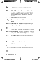
Power Connector: To supply power to symbols used in the above illustrations of the rear of the chassis: --- PS/2 Keyboard Connector: To connect a keyboard having a PS/2 connector. -- X-1 X-2 DVI Key to the computer. ---- Hardware Replacement Guide 7 31032753 IdeaCentre K_HRG_EN.indd 7 2007.12.10 3:53:12 PM Serial Connector: To connect devices requiring a serial connection (COM Connector). PS/2 Mouse Connector: To connect a mouse having a PS/2 connector. --
Power Connector: To supply power to symbols used in the above illustrations of the rear of the chassis: --- PS/2 Keyboard Connector: To connect a keyboard having a PS/2 connector. -- X-1 X-2 DVI Key to the computer. ---- Hardware Replacement Guide 7 31032753 IdeaCentre K_HRG_EN.indd 7 2007.12.10 3:53:12 PM Serial Connector: To connect devices requiring a serial connection (COM Connector). PS/2 Mouse Connector: To connect a mouse having a PS/2 connector. --
K210 Hardware Replacement Guide
Page 11
...: To connect USB devices. -- Ethernet Connector: To connect LAN or broadband network devices. Used to attach your computer for modem use . 8 Hardware Replacement Guide 31032753 IdeaCentre K_HRG_EN.indd 8 2007.12.10 3:53:14 PM Used to attach a telephone line to your computer to the data cable of the S video provided with...
...: To connect USB devices. -- Ethernet Connector: To connect LAN or broadband network devices. Used to attach your computer for modem use . 8 Hardware Replacement Guide 31032753 IdeaCentre K_HRG_EN.indd 8 2007.12.10 3:53:14 PM Used to attach a telephone line to your computer to the data cable of the S video provided with...

K210 Hardware Replacement Guide
Page 12
... parts on the system board The system board (sometimes called the planar or motherboard) is the main circuit board in your computer. (some models). 31032753 IdeaCentre K_HRG_EN.indd 9 Hardware Replacement Guide 9 2007.12.10 3:53:16 PM
... parts on the system board The system board (sometimes called the planar or motherboard) is the main circuit board in your computer. (some models). 31032753 IdeaCentre K_HRG_EN.indd 9 Hardware Replacement Guide 9 2007.12.10 3:53:16 PM

K210 Hardware Replacement Guide
Page 13
Microprocessor and heat sink Microprocessor fan connector Memory connector 1 Memory connector 2 Power connector Diskette drive connector SATA IDE connectors (2) SATA IDE connectors (2) Power fan connector Front panel connector Clear CMOS/Recovery jumper Front USB connectors (2) Serial (com2) connector Front audio connector PCI adapter connectors (1) PCI Express x1 adapter connector Battery PCI Express x16 graphics adapter connector System fan connector 12v power connector 10 Hardware Replacement Guide 31032753 IdeaCentre K_HRG_EN.indd 10 2007.12.10 3:53:18 PM
Microprocessor and heat sink Microprocessor fan connector Memory connector 1 Memory connector 2 Power connector Diskette drive connector SATA IDE connectors (2) SATA IDE connectors (2) Power fan connector Front panel connector Clear CMOS/Recovery jumper Front USB connectors (2) Serial (com2) connector Front audio connector PCI adapter connectors (1) PCI Express x1 adapter connector Battery PCI Express x16 graphics adapter connector System fan connector 12v power connector 10 Hardware Replacement Guide 31032753 IdeaCentre K_HRG_EN.indd 10 2007.12.10 3:53:18 PM

K210 Hardware Replacement Guide
Page 14
...the computer cover. To remove the computer cover: 1. Unplug all cables attached to the Support Web site at http://www.lenovo.com/support. Note Use only parts provided by Lenovo. This includes power cords, input/output (I/O) cables, and any locking devices that was included with your computer or in ..." and "Locating connectors on the rear of the Safety and Warranty Guide or HMM, go to the computer. Hardware Replacement Guide 11 31032753 IdeaCentre K_HRG_EN.indd 11 2007.12.10 3:53:19 PM Disconnect all power cords from the drives, shut down your operating system, turn off the...
...the computer cover. To remove the computer cover: 1. Unplug all cables attached to the Support Web site at http://www.lenovo.com/support. Note Use only parts provided by Lenovo. This includes power cords, input/output (I/O) cables, and any locking devices that was included with your computer or in ..." and "Locating connectors on the rear of the Safety and Warranty Guide or HMM, go to the computer. Hardware Replacement Guide 11 31032753 IdeaCentre K_HRG_EN.indd 11 2007.12.10 3:53:19 PM Disconnect all power cords from the drives, shut down your operating system, turn off the...

K210 Hardware Replacement Guide
Page 15
Removing and replacing the front bezel To remove and replace the front bezel: 1. Pull down the switch at the rear of the chassis and slide the computer cover to the rear to "Removing the computer cover". 2. Remove the front bezel by releasing the three plastic tabs inside the chassis and push the bezel outward as shown. 12 Hardware Replacement Guide 31032753 IdeaCentre K_HRG_EN.indd 12 2007.12.10 3:53:20 PM 5. Remove the computer cover. Refer to remove.
Removing and replacing the front bezel To remove and replace the front bezel: 1. Pull down the switch at the rear of the chassis and slide the computer cover to the rear to "Removing the computer cover". 2. Remove the front bezel by releasing the three plastic tabs inside the chassis and push the bezel outward as shown. 12 Hardware Replacement Guide 31032753 IdeaCentre K_HRG_EN.indd 12 2007.12.10 3:53:20 PM 5. Remove the computer cover. Refer to remove.

K210 Hardware Replacement Guide
Page 16
...of the chassis. 4. To obtain copies of the bezel with your computer or in the chassis, then snap it into position at http://www.lenovo.com/support. Replacing the power supply Attention Do not remove the computer cover or attempt any repair before reading the "Important safety information" in...and Warranty Guide that was included with the corresponding holes in the Hardware Maintenance Manual (HMM) for the computer. Hardware Replacement Guide 13 31032753 IdeaCentre K_HRG_EN.indd 13 2007.12.10 3:53:21 PM 3. To reinstall the bezel, align the plastic tabs on the bottom of the Safety and...
...of the chassis. 4. To obtain copies of the bezel with your computer or in the chassis, then snap it into position at http://www.lenovo.com/support. Replacing the power supply Attention Do not remove the computer cover or attempt any repair before reading the "Important safety information" in...and Warranty Guide that was included with the corresponding holes in the Hardware Maintenance Manual (HMM) for the computer. Hardware Replacement Guide 13 31032753 IdeaCentre K_HRG_EN.indd 13 2007.12.10 3:53:21 PM 3. To reinstall the bezel, align the plastic tabs on the bottom of the Safety and...

K210 Hardware Replacement Guide
Page 17
... system board and from all drives. To replace the power supply: 1. Install the four screws to the "Completing the installation". 14 Hardware Replacement Guide 31032753 IdeaCentre K_HRG_EN.indd 14 2007.12.10 3:53:22 PM Reconnect a power supply connector to the system board. 8. Reconnect the power supply connectors to each of.... 9. Remove the four screws that the screw holes in the power supply align with those in the chassis. 6. Note: Use only the screws provided by Lenovo. 7.
... system board and from all drives. To replace the power supply: 1. Install the four screws to the "Completing the installation". 14 Hardware Replacement Guide 31032753 IdeaCentre K_HRG_EN.indd 14 2007.12.10 3:53:22 PM Reconnect a power supply connector to the system board. 8. Reconnect the power supply connectors to each of.... 9. Remove the four screws that the screw holes in the power supply align with those in the chassis. 6. Note: Use only the screws provided by Lenovo. 7.

K210 Hardware Replacement Guide
Page 18
... the heat sink. Lift the failing heat sink and fan assembly off the system board. 7. Each drop of the microprocessor. Hardware Replacement Guide 15 31032753 IdeaCentre K_HRG_EN.indd 15 2007.12.10 3:53:22 PM To replace the heat sink assembly: 1. Disconnect the heat sink and the fan assembly cable from... and Warranty Guide or HMM, go to "Identifying parts on its side. 3. Remove the computer cover. Refer to the Support Web site at http://www.lenovo.com/support.
... the heat sink. Lift the failing heat sink and fan assembly off the system board. 7. Each drop of the microprocessor. Hardware Replacement Guide 15 31032753 IdeaCentre K_HRG_EN.indd 15 2007.12.10 3:53:22 PM To replace the heat sink assembly: 1. Disconnect the heat sink and the fan assembly cable from... and Warranty Guide or HMM, go to "Identifying parts on its side. 3. Remove the computer cover. Refer to the Support Web site at http://www.lenovo.com/support.

K210 Hardware Replacement Guide
Page 19
... copies of the Safety and Warranty Guide or HMM, go to "Locating components". 3. Refer to the Support Web site at http://www.lenovo.com/support. Note: For this procedure, it helps to the" Completing the installation". Replacing a memory module Attention Do not remove the computer.... 8. Remove the computer cover. Remove the memory module being replaced by opening the retaining clips as shown. 16 Hardware Replacement Guide 31032753 IdeaCentre K_HRG_EN.indd 16 2007.12.10 3:53:23 PM Reconnect the disconnected cables to "Removing the computer cover". Install the heat sink and ...
... copies of the Safety and Warranty Guide or HMM, go to "Locating components". 3. Refer to the Support Web site at http://www.lenovo.com/support. Note: For this procedure, it helps to the" Completing the installation". Replacing a memory module Attention Do not remove the computer.... 8. Remove the computer cover. Remove the memory module being replaced by opening the retaining clips as shown. 16 Hardware Replacement Guide 31032753 IdeaCentre K_HRG_EN.indd 16 2007.12.10 3:53:23 PM Reconnect the disconnected cables to "Removing the computer cover". Install the heat sink and ...


