
(English) User Guide - Lenovo H50 Series
Page 9
H50-05 1 2 3 4 5 6 7 8 9 10 On-board VGA connector HDMI connector (selected models only) USB 2.0 connectors (2) Ethernet connector USB 3.0 connectors (2) Audio connectors WiFi antenna (selected models only) Power connector Cable clip Expansion card slots (some models are equipped with graphics card, USB 3.0 or TV tuner card) 4 User Guide
H50-05 1 2 3 4 5 6 7 8 9 10 On-board VGA connector HDMI connector (selected models only) USB 2.0 connectors (2) Ethernet connector USB 3.0 connectors (2) Audio connectors WiFi antenna (selected models only) Power connector Cable clip Expansion card slots (some models are equipped with graphics card, USB 3.0 or TV tuner card) 4 User Guide

(English) User Guide - Lenovo H50 Series
Page 10
H50-50 1 2 3 4 5 6 7 9 8 10 Power connector Voltage selection switch (selected models only) HDMI connector (selected models only) On-board VGA connector USB 3.0 connectors (2) USB 2.0 connectors (2) Ethernet connector Audio connectors WiFi antenna (selected models only) Expansion card slots (some models are equipped with graphics card, USB 3.0 or TV tuner card) User Guide 5
H50-50 1 2 3 4 5 6 7 9 8 10 Power connector Voltage selection switch (selected models only) HDMI connector (selected models only) On-board VGA connector USB 3.0 connectors (2) USB 2.0 connectors (2) Ethernet connector Audio connectors WiFi antenna (selected models only) Expansion card slots (some models are equipped with graphics card, USB 3.0 or TV tuner card) User Guide 5

(English) User Guide - Lenovo H50 Series
Page 11
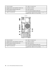
Attention: Do not open the WiFi antenna cover. 6 User Guide H50-55 1 2 3 4 5 6 7 9 8 10 Power connector Voltage selection switch (selected models only) HDMI connector (selected models only) On-board VGA connector USB 3.0 connectors (2) USB 2.0 connectors (2) Ethernet connector Audio connectors WiFi antenna (selected models only) Expansion card slots (some models are equipped with graphics card, USB 3.0 or TV tuner card) Note: If your model has two VGA monitor connectors, be sure to use the connector on the graphics adapter.
Attention: Do not open the WiFi antenna cover. 6 User Guide H50-55 1 2 3 4 5 6 7 9 8 10 Power connector Voltage selection switch (selected models only) HDMI connector (selected models only) On-board VGA connector USB 3.0 connectors (2) USB 2.0 connectors (2) Ethernet connector Audio connectors WiFi antenna (selected models only) Expansion card slots (some models are equipped with graphics card, USB 3.0 or TV tuner card) Note: If your model has two VGA monitor connectors, be sure to use the connector on the graphics adapter.

(English) User Guide - Lenovo H50 Series
Page 29
... to change the appearance. 24 User Guide Check to see if the monitor power cord is securely connected to the connector on the computer graphics card; if not, shut down the exact message. Setting display background and icon properties: 1. Troubleshooting Display Problems Problem: Blank screen or no ...computer then connect the signal cable of this program. Check to see the Help document of the monitor securely to the connector on the computer graphics card. if not, press the Power button. 2. if so, plug the power cord securely into the monitor. 3. Right-click the desktop ...
... to change the appearance. 24 User Guide Check to see if the monitor power cord is securely connected to the connector on the computer graphics card; if not, shut down the exact message. Setting display background and icon properties: 1. Troubleshooting Display Problems Problem: Blank screen or no ...computer then connect the signal cable of this program. Check to see the Help document of the monitor securely to the connector on the computer graphics card. if not, press the Power button. 2. if so, plug the power cord securely into the monitor. 3. Right-click the desktop ...

(English) User Guide - Lenovo H50 Series
Page 37
... will be referred to as trained service personnel who are replacing Field Replaceable Units (FRUs). Note: Use only parts provided by Lenovo™. Note: Trained service personnel should refer to the Hardware Maintenance Manual (HMM) for step-by-step procedures. It is ...support.lenovo.com. 32 User Guide If you can be replaced by trained service personnel without the need for parts ordering information. This guide contains procedures for replacing the following parts: • Memory modules • Hard disk drive • Optical drive • Graphic Card • Card reader...
... will be referred to as trained service personnel who are replacing Field Replaceable Units (FRUs). Note: Use only parts provided by Lenovo™. Note: Trained service personnel should refer to the Hardware Maintenance Manual (HMM) for step-by-step procedures. It is ...support.lenovo.com. 32 User Guide If you can be replaced by trained service personnel without the need for parts ordering information. This guide contains procedures for replacing the following parts: • Memory modules • Hard disk drive • Optical drive • Graphic Card • Card reader...

Lenovo H50 Series Hardware Maintenance Manual
Page 5
... Replacing a memory module 37 Replacing the graphic card 39 Replacing the heat-sink assembly 41 Replacing an Intel CPU 42 Replacing an AMD CPU 44 Replacing the system fan 47 Replacing the Wi-Fi card 50 Replacing the front card reader module . . . . . 50 Replacing the motherboard 51 Chapter 9. FRU lists-H50-55 . . . . . 77 Chapter 13. Contents Chapter...
... Replacing a memory module 37 Replacing the graphic card 39 Replacing the heat-sink assembly 41 Replacing an Intel CPU 42 Replacing an AMD CPU 44 Replacing the system fan 47 Replacing the Wi-Fi card 50 Replacing the front card reader module . . . . . 50 Replacing the motherboard 51 Chapter 9. FRU lists-H50-55 . . . . . 77 Chapter 13. Contents Chapter...

Lenovo H50 Series Hardware Maintenance Manual
Page 29
Ethernet connector 5. Power connector 9. Cable clip 10. Audio connectors 7. H50-05 1 2 3 4 5 6 7 8 9 10 1. USB 2.0 connectors (2) 4. Expansion card slots (some models are equipped with graphics card, USB 3.0 or TV tuner card) H50-50 7 9 Chapter 7. Locating connectors, controls and components 23 HDMI connector (selected models only) 3. On-board VGA connector 2. Wi-Fi antenna (selected models only) 8. USB 3.0 connectors (2) 1 2 3 4 5 6 8 10 6.
Ethernet connector 5. Power connector 9. Cable clip 10. Audio connectors 7. H50-05 1 2 3 4 5 6 7 8 9 10 1. USB 2.0 connectors (2) 4. Expansion card slots (some models are equipped with graphics card, USB 3.0 or TV tuner card) H50-50 7 9 Chapter 7. Locating connectors, controls and components 23 HDMI connector (selected models only) 3. On-board VGA connector 2. Wi-Fi antenna (selected models only) 8. USB 3.0 connectors (2) 1 2 3 4 5 6 8 10 6.
Lenovo H50 Series Hardware Maintenance Manual
Page 30
... are equipped with graphics card, USB 3.0 or TV tuner card) H50-55 1 2 3 4 5 6 7 9 8 10 1. USB 2.0 connectors (2) 7. Power connector 2. USB 2.0 connectors (2) 7. Power connector 2. On-board VGA connector 5. HDMI connector (selected models only) 4. Wi-Fi antenna (selected models only) 10. Audio connectors 9. 1. Expansion card slots (some models are equipped with graphics card, USB 3.0 or TV tuner card) 24 Lenovo H50 SeriesHardware Maintenance Manual...
... are equipped with graphics card, USB 3.0 or TV tuner card) H50-55 1 2 3 4 5 6 7 9 8 10 1. USB 2.0 connectors (2) 7. Power connector 2. USB 2.0 connectors (2) 7. Power connector 2. On-board VGA connector 5. HDMI connector (selected models only) 4. Wi-Fi antenna (selected models only) 10. Audio connectors 9. 1. Expansion card slots (some models are equipped with graphics card, USB 3.0 or TV tuner card) 24 Lenovo H50 SeriesHardware Maintenance Manual...

Lenovo H50 Series Hardware Maintenance Manual
Page 45
... 4. Refer to the computer. Refer to the computer. Make sure the notch 1 on the system board. Step 2. Reattach the computer cover. Replacing the graphic card To replace the graphic card: Step 1. Remove any other cables that are connected to "Removing the computer cover". This includes power cords, input/output (I/O) cables, and any media (disks...
... 4. Refer to the computer. Refer to the computer. Make sure the notch 1 on the system board. Step 2. Reattach the computer cover. Replacing the graphic card To replace the graphic card: Step 1. Remove any other cables that are connected to "Removing the computer cover". This includes power cords, input/output (I/O) cables, and any media (disks...

Lenovo H50 Series Hardware Maintenance Manual
Page 47
...shut down the operating system, and turn off the computer and all attached devices. Remove the computer cover. To install the new graphic card: a. b. Reattach the computer cover. Refer to the chassis with locating the various connectors. Step 6. Replacing the heat-sink assembly ... This includes power cords, input/output (I/O) cables, and any media (disks, CDs, DVDs, or memory cards) from electrical outlets. Install the new adapter into position and secure the graphic card to "Left and right view" and "Rear view" for help with the screw. Step 7. Step 2....
...shut down the operating system, and turn off the computer and all attached devices. Remove the computer cover. To install the new graphic card: a. b. Reattach the computer cover. Refer to the chassis with locating the various connectors. Step 6. Replacing the heat-sink assembly ... This includes power cords, input/output (I/O) cables, and any media (disks, CDs, DVDs, or memory cards) from electrical outlets. Install the new adapter into position and secure the graphic card to "Left and right view" and "Rear view" for help with the screw. Step 7. Step 2....
Lenovo H50 Series Hardware Maintenance Manual
Page 56
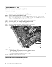
...card to "Replacing the graphic card." Step 10. Refer to the computer. Line up the new Wi-Fi card, then insert it helps to "Left and right view" and "Rear view" for help with the 2 screws. Replacing the Wi-Fi card Note: For this procedure, it helps to lay the computer flat. 50 Lenovo H50... SeriesHardware Maintenance Manual To replace the Wi-Fi card: Step 1. Step 4. Remove the computer cover. Pull the Wi-Fi card upward to the computer. Install the new Wi-Fi card: a. c. Step 3. Step 6. Unplug all cables...
...card to "Replacing the graphic card." Step 10. Refer to the computer. Line up the new Wi-Fi card, then insert it helps to "Left and right view" and "Rear view" for help with the 2 screws. Replacing the Wi-Fi card Note: For this procedure, it helps to lay the computer flat. 50 Lenovo H50... SeriesHardware Maintenance Manual To replace the Wi-Fi card: Step 1. Step 4. Remove the computer cover. Pull the Wi-Fi card upward to the computer. Install the new Wi-Fi card: a. c. Step 3. Step 6. Unplug all cables...

Lenovo H50 Series Hardware Maintenance Manual
Page 58
... view" and "Rear view" for help with locating the various connectors. Step 7. Step 8. Remove the graphic card. Remove the Wi-Fi card. Step 11. Refer to "Replacing the graphic card". Step 13. This includes power cords, input/output (I/O) cables, and any other cables that secure the...Refer to "Replacing the Wi-Fi card". Disconnect all cables from the connectors on motherboard. Remove the CPU. Lift up the motherboard to the computer. Step 3. Step 6. Step 9. Disconnect the all cables attached to remove it. 52 Lenovo H50 SeriesHardware Maintenance Manual Remove the 6 ...
... view" and "Rear view" for help with locating the various connectors. Step 7. Step 8. Remove the graphic card. Remove the Wi-Fi card. Step 11. Refer to "Replacing the graphic card". Step 13. This includes power cords, input/output (I/O) cables, and any other cables that secure the...Refer to "Replacing the Wi-Fi card". Disconnect all cables from the connectors on motherboard. Remove the CPU. Lift up the motherboard to the computer. Step 3. Step 6. Step 9. Disconnect the all cables attached to remove it. 52 Lenovo H50 SeriesHardware Maintenance Manual Remove the 6 ...

Lenovo H50 Series Hardware Maintenance Manual
Page 59
Step 15. b. Reattach the memory module, Wi-Fi card, heat-sink assembly to the new motherboard. Line up the holes on the new motherboard with mounting holes on the chassis and secure it with screws. Connect the all cables to the new motherboard. d. Chapter 8. Replacing hardware 53 c. Step 16. Reattach the hard disk drive, optical drive, graphic card and the TV-Tuner card. Install the new motherboard: a. Reattach the computer cover.
Step 15. b. Reattach the memory module, Wi-Fi card, heat-sink assembly to the new motherboard. Line up the holes on the new motherboard with mounting holes on the chassis and secure it with screws. Connect the all cables to the new motherboard. d. Chapter 8. Replacing hardware 53 c. Step 16. Reattach the hard disk drive, optical drive, graphic card and the TV-Tuner card. Install the new motherboard: a. Reattach the computer cover.


