User Guide
Page 3
... computer 29 About NVIDIA® OptimusTM (on select models 30 Chapter 3. CRU instructions 35 Replacing the battery 35 Replacing the hard disk drive 37 Replacing memory ...44 Replacing the wireless LAN card 48 Removing the optical drive 50 Trademarks 52 Index...53 i Getting to the Internet 31 Wired connection ...31 Wireless...
... computer 29 About NVIDIA® OptimusTM (on select models 30 Chapter 3. CRU instructions 35 Replacing the battery 35 Replacing the hard disk drive 37 Replacing memory ...44 Replacing the wireless LAN card 48 Removing the optical drive 50 Trademarks 52 Index...53 i Getting to the Internet 31 Wired connection ...31 Wireless...
User Guide
Page 13
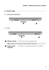
Note: For details, see "System status indicators" on page 24. Chapter 1. Getting to know your computer Front view „ G480/G485/G580/G585 „ G780 2 1 2 1 a Memory card slot Insert memory cards (not supplied) here. b System status indicators For details, see "Using memory cards (not supplied)" on page 27. 9
Note: For details, see "System status indicators" on page 24. Chapter 1. Getting to know your computer Front view „ G480/G485/G580/G585 „ G780 2 1 2 1 a Memory card slot Insert memory cards (not supplied) here. b System status indicators For details, see "Using memory cards (not supplied)" on page 27. 9
User Guide
Page 19
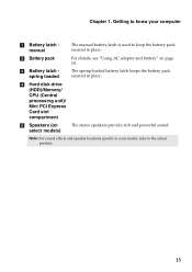
d Hard disk drive (HDD)/Memory/ CPU (Central processing unit)/ Mini PCI Express Card slot compartment e Speakers (on page 18. Getting to know your model, refer to keep the battery pack ...
d Hard disk drive (HDD)/Memory/ CPU (Central processing unit)/ Mini PCI Express Card slot compartment e Speakers (on page 18. Getting to know your model, refer to keep the battery pack ...
User Guide
Page 28
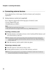
...) Note: • Insert ONLY one card in the slot at a time. • This card reader does not support SDIO devices (e.g., SDIO Bluetooth, etc.). Inserting a memory card 1 Push the dummy card until you hear a click. Note: The dummy card is not in use . 2 Slide the... memory card in features and connection capabilities. „ Using memory cards (not supplied) Your computer supports the following types of the memory card slot. Retain the dummy card for preventing dust and small particles from entering the inside...
...) Note: • Insert ONLY one card in the slot at a time. • This card reader does not support SDIO devices (e.g., SDIO Bluetooth, etc.). Inserting a memory card 1 Push the dummy card until you hear a click. Note: The dummy card is not in use . 2 Slide the... memory card in features and connection capabilities. „ Using memory cards (not supplied) Your computer supports the following types of the memory card slot. Retain the dummy card for preventing dust and small particles from entering the inside...
User Guide
Page 42
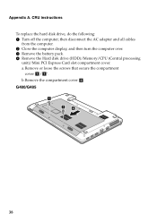
Appendix A. b.Remove the compartment cover b. then disconnect the AC adapter and all cables from the computer. 2 Close the computer display, and then turn the computer over. 3 Remove the battery pack. 4 Remove the Hard disk drive (HDD)/Memory/CPU (Central processing unit)/Mini PCI Express Card slot compartment cover. a.Remove or loose the screws that secure the compartment cover a/ a '. G480/G485 1 1 2 38 CRU instructions To replace the hard disk drive, do the following: 1 Turn off the computer;
Appendix A. b.Remove the compartment cover b. then disconnect the AC adapter and all cables from the computer. 2 Close the computer display, and then turn the computer over. 3 Remove the battery pack. 4 Remove the Hard disk drive (HDD)/Memory/CPU (Central processing unit)/Mini PCI Express Card slot compartment cover. a.Remove or loose the screws that secure the compartment cover a/ a '. G480/G485 1 1 2 38 CRU instructions To replace the hard disk drive, do the following: 1 Turn off the computer;
User Guide
Page 48
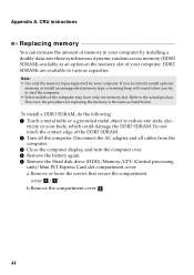
...the computer. 3 Close the computer display, and turn the computer over. 4 Remove the battery again. 5 Remove the Hard disk drive (HDD)/Memory/CPU (Central processing unit)/Mini PCI Express Card slot compartment cover. Appendix A. Refer to reduce any static elec- Do not touch the contact ...DDR3 SDRAM, do the following: 1 Touch a metal table or a grounded metal object to the actual product. If you incorrectly install optional memory, or install an unsupported memory type, a warning beep will sound when you try to start the computer. • Select models of the DDR3 SDRAM. 2 Turn off ...
...the computer. 3 Close the computer display, and turn the computer over. 4 Remove the battery again. 5 Remove the Hard disk drive (HDD)/Memory/CPU (Central processing unit)/Mini PCI Express Card slot compartment cover. Appendix A. Refer to reduce any static elec- Do not touch the contact ...DDR3 SDRAM, do the following: 1 Touch a metal table or a grounded metal object to the actual product. If you incorrectly install optional memory, or install an unsupported memory type, a warning beep will sound when you try to start the computer. • Select models of the DDR3 SDRAM. 2 Turn off ...
User Guide
Page 50
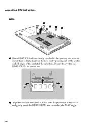
Appendix A. Be sure to save the old DDR3 SDRAM for the new one of them to make room for future use. 2 1 1 7 Align the notch of the DDR3 SDRAM with the protrusion of the socket at a 30-45° angle. 46 CRU instructions G780 1 1 ' 1 ' 1 1 ' 1 ' 2 6 If two DDR3 SDRAMs are already installed in the memory slot, remove one by pressing out on the latches on both edges of the socket and gently insert the DDR3 SDRAM into the socket at the same time.
Appendix A. Be sure to save the old DDR3 SDRAM for the new one of them to make room for future use. 2 1 1 7 Align the notch of the DDR3 SDRAM with the protrusion of the socket at a 30-45° angle. 46 CRU instructions G780 1 1 ' 1 ' 1 1 ' 1 ' 2 6 If two DDR3 SDRAMs are already installed in the memory slot, remove one by pressing out on the latches on both edges of the socket and gently insert the DDR3 SDRAM into the socket at the same time.
User Guide
Page 51
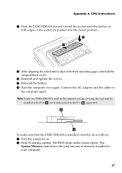
CRU instructions 8 Push the DDR3 SDRAM inward toward the socket until the latches on both edges of memory installed in SLOT-1 ( : upper slot). Connect the AC adapter and the cables to the computer again. Note: If only one DDR3 SDRAM is installed correctly, ... pushed into the closed position. 2 1 9 After aligning the attachment clips with their matching gaps, reinstall the compartment cover. 0 Reinstall and tighten the screws. The System Memory item shows the total amount of the socket are servicing, the card must be installed in SLOT-0 ( : lower slot), but not in your computer. 47...
CRU instructions 8 Push the DDR3 SDRAM inward toward the socket until the latches on both edges of memory installed in SLOT-1 ( : upper slot). Connect the AC adapter and the cables to the computer again. Note: If only one DDR3 SDRAM is installed correctly, ... pushed into the closed position. 2 1 9 After aligning the attachment clips with their matching gaps, reinstall the compartment cover. 0 Reinstall and tighten the screws. The System Memory item shows the total amount of the socket are servicing, the card must be installed in SLOT-0 ( : lower slot), but not in your computer. 47...
User Guide
Page 52
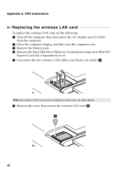
... and all cables from the computer. 2 Close the computer display, and then turn the computer over. 3 Remove the battery pack. 4 Remove the Hard disk drive/Memory/Central processing unit/Mini PCI Express Card slot compartment cover. 5 Disconnect the two wireless LAN cables (one black, one white) a . 1 Note: The wireless LAN card...
... and all cables from the computer. 2 Close the computer display, and then turn the computer over. 3 Remove the battery pack. 4 Remove the Hard disk drive/Memory/Central processing unit/Mini PCI Express Card slot compartment cover. 5 Disconnect the two wireless LAN cables (one black, one white) a . 1 Note: The wireless LAN card...
User Guide
Page 54
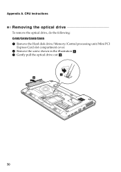
Appendix A. CRU instructions Removing the optical drive To remove the optical drive, do the following: G480/G485/G580/G585 1 Remove the Hard disk drive/Memory/Central processing unit/Mini PCI Express Card slot compartment cover. 2 Remove the screw shown in the illustration a . 3 Gently pull the optical drive out b . 1 2 50
Appendix A. CRU instructions Removing the optical drive To remove the optical drive, do the following: G480/G485/G580/G585 1 Remove the Hard disk drive/Memory/Central processing unit/Mini PCI Express Card slot compartment cover. 2 Remove the screw shown in the illustration a . 3 Gently pull the optical drive out b . 1 2 50
User Guide
Page 55
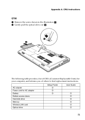
CRU instructions G780 1 Remove the screw shown in the illustration a . 2 Gently pull the optical drive out b . 1 2 The following table provides a list of where to find replacement instructions. AC adapter Power cord for your computer, and informs you of CRUs (Customer Replaceable Units) for AC adapter Battery Bottom access doors Hard disk drive Memory Wireless LAN card Optical drive Setup Poster O O O User Guide O O O O O O 51 Appendix A.
CRU instructions G780 1 Remove the screw shown in the illustration a . 2 Gently pull the optical drive out b . 1 2 The following table provides a list of where to find replacement instructions. AC adapter Power cord for your computer, and informs you of CRUs (Customer Replaceable Units) for AC adapter Battery Bottom access doors Hard disk drive Memory Wireless LAN card Optical drive Setup Poster O O O User Guide O O O O O O 51 Appendix A.
Hardware Maintenance Manual
Page 3
...Hard-disk password 24 Supervisor password 24 Power management 25 Screen blank mode 25 Sleep (standby) mode 25 Hibernation mode 26 Lenovo G480/G485/G580/G585/G780 ........27 Specifications 27 Status indicators 29 Fn key combinations 31 FRU replacement notices 32 Screw notices 32 Removing and replacing an ...drive (HDD)/ Memory/Central processing unit/Mini PCI Express Card slot compartment cover 36 1040 Hard disk drive 39 1050 Optical drive 43 1060 DIMM 45 1070 PCI Express Mini Card for wireless LAN/WAN 47 1080 Keyboard 49 1090 Keyboard bezel 52 1100 Speakers (Lenovo G480/G485/ ...
...Hard-disk password 24 Supervisor password 24 Power management 25 Screen blank mode 25 Sleep (standby) mode 25 Hibernation mode 26 Lenovo G480/G485/G580/G585/G780 ........27 Specifications 27 Status indicators 29 Fn key combinations 31 FRU replacement notices 32 Screw notices 32 Removing and replacing an ...drive (HDD)/ Memory/Central processing unit/Mini PCI Express Card slot compartment cover 36 1040 Hard disk drive 39 1050 Optical drive 43 1060 DIMM 45 1070 PCI Express Mini Card for wireless LAN/WAN 47 1080 Keyboard 49 1090 Keyboard bezel 52 1100 Speakers (Lenovo G480/G485/ ...
Hardware Maintenance Manual
Page 31
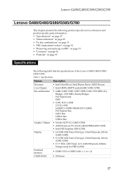
...FHD (G780) Standard memory • DDR3-1333 or DDR3-1600 (× 1 or × 2) CMOS RAM • 256 bytes 27 Specifications Feature Description Processor • Intel Chief River/Intel Huron River/AMD Deccan Core Chipset • Intel HM76 (HM75 ready)(G480/G580/G780) Bus... 1366x768 pixels, 200 nit (G580/G585) • 17.3" HD+ LED Panel, 16:9, 1600x900 pixels, 220nits; Lenovo G480/G485/G580/G585/G780 Lenovo G480/G485/G580/G585/G780 This chapter presents the following product-specific service references and product-specific parts information: • "Specifications" on page ...
...FHD (G780) Standard memory • DDR3-1333 or DDR3-1600 (× 1 or × 2) CMOS RAM • 256 bytes 27 Specifications Feature Description Processor • Intel Chief River/Intel Huron River/AMD Deccan Core Chipset • Intel HM76 (HM75 ready)(G480/G580/G780) Bus... 1366x768 pixels, 200 nit (G580/G585) • 17.3" HD+ LED Panel, 16:9, 1600x900 pixels, 220nits; Lenovo G480/G485/G580/G585/G780 Lenovo G480/G485/G580/G585/G780 This chapter presents the following product-specific service references and product-specific parts information: • "Specifications" on page ...
Hardware Maintenance Manual
Page 32
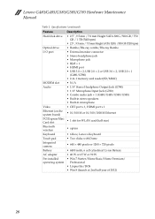
... × 2 or USB 3.0 × 2, USB 2.0 × 1 (G480/G580) • 2-in-1 memory card reader(SD/MMC) MODEM slot • N/A Audio • 1/8" Stereo Headphone Output Jack (G780) • 1/8" Microphone Input Jack (G780) • Combo audio jack × 1 (G480/G485/G580/G585) • Built-in stereo speakers •... PCI Express Mini Card slot • 1 slot for WLAN card (half size) Bluetooth wireless • option Keyboard • 6 Row, Lenovo Keyboard Touch pad • Two clicks with Dome Integrated camera • 640 × 480 pixels or 1280 × 720 pixels Battery &#...
... × 2 or USB 3.0 × 2, USB 2.0 × 1 (G480/G580) • 2-in-1 memory card reader(SD/MMC) MODEM slot • N/A Audio • 1/8" Stereo Headphone Output Jack (G780) • 1/8" Microphone Input Jack (G780) • Combo audio jack × 1 (G480/G485/G580/G585) • Built-in stereo speakers •... PCI Express Mini Card slot • 1 slot for WLAN card (half size) Bluetooth wireless • option Keyboard • 6 Row, Lenovo Keyboard Touch pad • Two clicks with Dome Integrated camera • 640 × 480 pixels or 1280 × 720 pixels Battery &#...

Hardware Maintenance Manual
Page 40
Lenovo G480/G485/G580/G585/G780 Hardware Maintenance Manual 1030 Optical drive/Hard disk drive (HDD)/Memory/Central processing unit/Mini PCI Express Card slot compartment cover For access, remove this FRU: • "1010 Battery pack" on page 34 Figure 3. Lenovo G480: 1 1 2 Lenovo G580: 1 1 2 36 Removal steps of Optical drive/Hard disk drive (HDD)/Memory/Central processing unit/Mini PCI Express Card slot compartment cover Lenovo G480/G485/G580/G585 Remove the two screws a, then remove the compartment cover in the direction shown by the arrow b.
Lenovo G480/G485/G580/G585/G780 Hardware Maintenance Manual 1030 Optical drive/Hard disk drive (HDD)/Memory/Central processing unit/Mini PCI Express Card slot compartment cover For access, remove this FRU: • "1010 Battery pack" on page 34 Figure 3. Lenovo G480: 1 1 2 Lenovo G580: 1 1 2 36 Removal steps of Optical drive/Hard disk drive (HDD)/Memory/Central processing unit/Mini PCI Express Card slot compartment cover Lenovo G480/G485/G580/G585 Remove the two screws a, then remove the compartment cover in the direction shown by the arrow b.
Hardware Maintenance Manual
Page 43
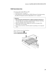
The hard disk drive is in order: • "1010 Battery pack" on page 34 • "1030 Optical drive/Hard disk drive (HDD)/Memory/Central processing unit/Mini PCI Express Card slot compartment cover" on page 36 Attention: • Do not drop the hard disk drive or apply any ... if possible. • Never remove the drive while the system is operating or is sensitive to it. Lenovo G480/G485/G580/G585/G780 1040 Hard disk drive For access, remove these FRUs in suspend mode. Lenovo G480/G485/G580/G585 1 1 39 Improper handling can cause damages and permanent loss of hard disk drive...
The hard disk drive is in order: • "1010 Battery pack" on page 34 • "1030 Optical drive/Hard disk drive (HDD)/Memory/Central processing unit/Mini PCI Express Card slot compartment cover" on page 36 Attention: • Do not drop the hard disk drive or apply any ... if possible. • Never remove the drive while the system is operating or is sensitive to it. Lenovo G480/G485/G580/G585/G780 1040 Hard disk drive For access, remove these FRUs in suspend mode. Lenovo G480/G485/G580/G585 1 1 39 Improper handling can cause damages and permanent loss of hard disk drive...
Hardware Maintenance Manual
Page 47
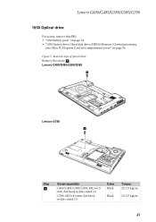
Removal steps of optical drive Remove the screw a. Lenovo G480/G485/G580/G585 1 Lenovo G780 1 Step a Screw (quantity) G480/G485/G580/G585: M2.5×6.0 mm, flat-head, nylok-coated (1) G780: M2.5×8.0 mm, flat-head, nylok-coated (1) Color Black Black Torque 2.0-2.5 kgfcm 2.0-2.5 kgfcm 43 Lenovo G480/G485/G580/G585/G780 1050 Optical drive For access, remove this FRU: • "1010 Battery pack" on page 34 • "1030 Optical drive/Hard disk drive (HDD)/Memory/Central processing unit/Mini PCI Express Card slot compartment cover" on page 36 Figure 5.
Removal steps of optical drive Remove the screw a. Lenovo G480/G485/G580/G585 1 Lenovo G780 1 Step a Screw (quantity) G480/G485/G580/G585: M2.5×6.0 mm, flat-head, nylok-coated (1) G780: M2.5×8.0 mm, flat-head, nylok-coated (1) Color Black Black Torque 2.0-2.5 kgfcm 2.0-2.5 kgfcm 43 Lenovo G480/G485/G580/G585/G780 1050 Optical drive For access, remove this FRU: • "1010 Battery pack" on page 34 • "1030 Optical drive/Hard disk drive (HDD)/Memory/Central processing unit/Mini PCI Express Card slot compartment cover" on page 36 Figure 5.
Hardware Maintenance Manual
Page 49
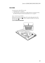
Lenovo G480/G485/G580/G585/G780 1060 DIMM For access, remove these FRUs in the direction shown by arrow b. Lenovo G480/G485/G580/G585 2 1 1 45 Removal steps of DIMM Release the two latches on both edges of the socket at the same time in the direction shown by arrows a, and then unplug the DIMM in order: • "1010 Battery pack" on page 34 • "1030 Optical drive/Hard disk drive (HDD)/Memory/Central processing unit/Mini PCI Express Card slot compartment cover" on page 36 Figure 6.
Lenovo G480/G485/G580/G585/G780 1060 DIMM For access, remove these FRUs in the direction shown by arrow b. Lenovo G480/G485/G580/G585 2 1 1 45 Removal steps of DIMM Release the two latches on both edges of the socket at the same time in the direction shown by arrows a, and then unplug the DIMM in order: • "1010 Battery pack" on page 34 • "1030 Optical drive/Hard disk drive (HDD)/Memory/Central processing unit/Mini PCI Express Card slot compartment cover" on page 36 Figure 6.
Hardware Maintenance Manual
Page 51
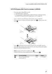
... card has 2 cables in step a. Step b Screw (quantity) M2.0×3.0 mm, flat-head, nylok-coated (1) Color Black Torque 1.5-2.0 kgfcm 47 Lenovo G480/G485/G580/G585/G780 1070 PCI Express Mini Card for wireless LAN/WAN Disconnect the two wireless LAN cables (black, white) a, and then remove the screw b. 1 2 ...For access, remove these FRUs in order: • "1010 Battery pack" on page 34 • "1030 Optical drive/Hard disk drive (HDD)/Memory/Central processing unit/Mini PCI Express Card slot compartment cover" on page 36 Figure 7. wireless LAN card in some models may have 3 cables in ...
... card has 2 cables in step a. Step b Screw (quantity) M2.0×3.0 mm, flat-head, nylok-coated (1) Color Black Torque 1.5-2.0 kgfcm 47 Lenovo G480/G485/G580/G585/G780 1070 PCI Express Mini Card for wireless LAN/WAN Disconnect the two wireless LAN cables (black, white) a, and then remove the screw b. 1 2 ...For access, remove these FRUs in order: • "1010 Battery pack" on page 34 • "1030 Optical drive/Hard disk drive (HDD)/Memory/Central processing unit/Mini PCI Express Card slot compartment cover" on page 36 Figure 7. wireless LAN card in some models may have 3 cables in ...
Hardware Maintenance Manual
Page 53
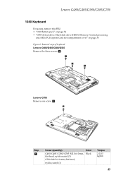
Removal steps of keyboard Lenovo G480/G485/G580/G585 Remove the three screws a. 1 1 1 Lenovo G780 Remove one screw a. 1 Step a Screw (quantity) Color G480/G485/G580/G585: M2.0×6.0 mm, flat-head, nylok-coated (3) G780: M2.5×8.0 mm, flat-head, nylok-coated (1) Black Torque 2.0-2.5 kgfcm 49 Lenovo G480/G485/G580/G585/G780 1080 Keyboard For access, remove this FRU: • "1010 Battery pack" on page 34 • "1030 Optical drive/Hard disk drive (HDD)/Memory/Central processing unit/Mini PCI Express Card slot compartment cover" on page 36 Figure 8.
Removal steps of keyboard Lenovo G480/G485/G580/G585 Remove the three screws a. 1 1 1 Lenovo G780 Remove one screw a. 1 Step a Screw (quantity) Color G480/G485/G580/G585: M2.0×6.0 mm, flat-head, nylok-coated (3) G780: M2.5×8.0 mm, flat-head, nylok-coated (1) Black Torque 2.0-2.5 kgfcm 49 Lenovo G480/G485/G580/G585/G780 1080 Keyboard For access, remove this FRU: • "1010 Battery pack" on page 34 • "1030 Optical drive/Hard disk drive (HDD)/Memory/Central processing unit/Mini PCI Express Card slot compartment cover" on page 36 Figure 8.


