Safety and Warranty guide
Page 21
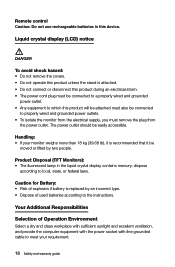
... outlet. Liquid crystal display (LCD) notice DANGER To avoid shock hazard: • Do not remove the covers. • Do not operate this product unless the stand is recommended that it is attached. • Do not connect or disconnect this product during an electrical storm. • The power cord plug must be...
... outlet. Liquid crystal display (LCD) notice DANGER To avoid shock hazard: • Do not remove the covers. • Do not operate this product unless the stand is recommended that it is attached. • Do not connect or disconnect this product during an electrical storm. • The power cord plug must be...
Lenovo C3/C4/C5 Series User Guide
Page 4
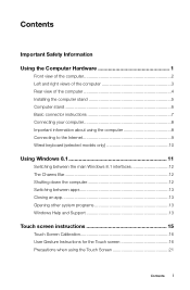
... Information Using the Computer Hardware 1 Front view of the computer 2 Left and right views of the computer 3 Rear view of the computer 4 Installing the computer stand 5 Computer stand 6 Basic connector instructions 7 Connecting your computer 8 Important information about using the computer 8 Connecting to the Internet 9 Wired keyboard (selected models only 10 Using Windows...
... Information Using the Computer Hardware 1 Front view of the computer 2 Left and right views of the computer 3 Rear view of the computer 4 Installing the computer stand 5 Computer stand 6 Basic connector instructions 7 Connecting your computer 8 Important information about using the computer 8 Connecting to the Internet 9 Wired keyboard (selected models only 10 Using Windows...

Lenovo C3/C4/C5 Series User Guide
Page 10
Pull the hand screw rings up the stand base with the hand screws. Installing the computer stand Note: It may be helpful to place the computer face-down on the stand base. 3. Line up , then secure the stand base to the stand holder with the mounting holes in the stand holder, then open both of the fixed rubber caps on a soft flat surface for this procedure. Lenovo recommends that you use a blanket, towel, or other soft cloth to protect the screen from scratches or other damage. 1. User Guide 5 Raise the stand holder. 2.
Pull the hand screw rings up the stand base with the hand screws. Installing the computer stand Note: It may be helpful to place the computer face-down on the stand base. 3. Line up , then secure the stand base to the stand holder with the mounting holes in the stand holder, then open both of the fixed rubber caps on a soft flat surface for this procedure. Lenovo recommends that you use a blanket, towel, or other soft cloth to protect the screen from scratches or other damage. 1. User Guide 5 Raise the stand holder. 2.

Lenovo C3/C4/C5 Series User Guide
Page 11
It can be rotated 5° forward and 25° backward. 6 User Guide Press down the hand screw rings and rubber caps. Computer stand Use the stand to position the display to your preference. 4.
It can be rotated 5° forward and 25° backward. 6 User Guide Press down the hand screw rings and rubber caps. Computer stand Use the stand to position the display to your preference. 4.
Lenovo C3/C4/C5 Series User Guide
Page 42
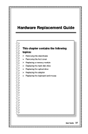
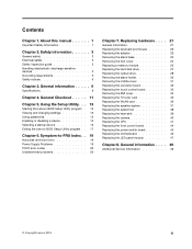
Hardware Replacement Guide This chapter contains the following topics: Ø Removing the stand base Ø Removing the foot cover Ø Replacing a memory module Ø Replacing the hard disk drive Ø Replacing the optical drive Ø Replacing the adapter Ø Replacing the keyboard and mouse User Guide 37
Hardware Replacement Guide This chapter contains the following topics: Ø Removing the stand base Ø Removing the foot cover Ø Replacing a memory module Ø Replacing the hard disk drive Ø Replacing the optical drive Ø Replacing the adapter Ø Replacing the keyboard and mouse User Guide 37
Lenovo C3/C4/C5 Series User Guide
Page 46
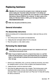
... and all power and signal cables from electrical outlets. 3. Disconnect all power cords from the computer. 3. User Guide 41 Removing the stand base Attention: Turn off the power to place the computer face-down the operating system, and turn off the computer and all attached devices...down on a flat, stable surface. Turn off the computer and wait 3 to 5 minutes to the Support Web site at: http://support.lenovo.com Note: Use only parts provided by Lenovo. Remove any other damage. 1. This includes power cords, input/output (I/O) cables, and any media (disks, CDs, or memory cards) ...
... and all power and signal cables from electrical outlets. 3. Disconnect all power cords from the computer. 3. User Guide 41 Removing the stand base Attention: Turn off the power to place the computer face-down the operating system, and turn off the computer and all attached devices...down on a flat, stable surface. Turn off the computer and wait 3 to 5 minutes to the Support Web site at: http://support.lenovo.com Note: Use only parts provided by Lenovo. Remove any other damage. 1. This includes power cords, input/output (I/O) cables, and any media (disks, CDs, or memory cards) ...
Lenovo C3/C4/C5 Series User Guide
Page 47
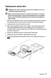
4. Refer to "Installing the computer stand" to protect the touch screen from scratches or other soft cloth to reinstall the stand base. To release the stand base from the drives, shut down before removing the cover. Lenovo recommends that you use a blanket, towel, or other damage. 1. Remove any... media (disks, CDs, or memory cards) from the stand holder, turn off the ...
4. Refer to "Installing the computer stand" to protect the touch screen from scratches or other soft cloth to reinstall the stand base. To release the stand base from the drives, shut down before removing the cover. Lenovo recommends that you use a blanket, towel, or other damage. 1. Remove any... media (disks, CDs, or memory cards) from the stand holder, turn off the ...
Lenovo C3/C4/C5 Series User Guide
Page 48
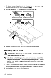
...attached devices. 2. Refer to "Removing the foot base". 5. Refer to "Left and right views" and "Rear view" for this procedure. Lift up the stand holder. User Guide 43 Remove any other cables that you use a blanket, towel, or other damage. 1. 3. Note: It may be helpful to the ...computer. Lift up the stand holder then slide out the foot cover as shown. 1 2 6. b. Lenovo recommends that are connected to place the computer face-down on the back of the computer, then slide it cool down...
...attached devices. 2. Refer to "Removing the foot base". 5. Refer to "Left and right views" and "Rear view" for this procedure. Lift up the stand holder. User Guide 43 Remove any other cables that you use a blanket, towel, or other damage. 1. 3. Note: It may be helpful to the ...computer. Lift up the stand holder then slide out the foot cover as shown. 1 2 6. b. Lenovo recommends that are connected to place the computer face-down on the back of the computer, then slide it cool down...

Lenovo C3/C4/C5 Series User Guide
Page 49
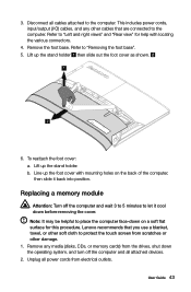
...to the computer. This includes power cords, input/output (I/O) cables, and any other cables that are connected to the computer. Remove the stand base. Refer to "Removing the stand base". 5. All of the memory socket to release the memory module and gently pull the memory module upward to "Left and right ...views" and "Rear view" for help with the memory socket, then insert it from its socket. Reattach the foot cover and stand base. 44 User Guide Push out the latches on the top edge. Make sure the latches lock the memory module in place. 8. Remove the foot...
...to the computer. This includes power cords, input/output (I/O) cables, and any other cables that are connected to the computer. Remove the stand base. Refer to "Removing the stand base". 5. All of the memory socket to release the memory module and gently pull the memory module upward to "Left and right ...views" and "Rear view" for help with the memory socket, then insert it from its socket. Reattach the foot cover and stand base. 44 User Guide Push out the latches on the top edge. Make sure the latches lock the memory module in place. 8. Remove the foot...
Lenovo C3/C4/C5 Series User Guide
Page 50
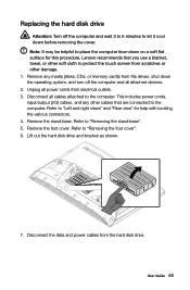
... flat surface for help with locating the various connectors. 4. Remove any other cables that you use a blanket, towel, or other damage. 1. Remove the stand base. This includes power cords, input/output (I/O) cables, and any media (disks, CDs, or memory cards) from the drives, shut down the operating ... data and power cables from the hard disk drive. Lift out the hard disk drive and bracket as shown. 7. User Guide 45 Lenovo recommends that are connected to protect the touch screen from scratches or other soft cloth to the computer. Disconnect all cables attached to "...
... flat surface for help with locating the various connectors. 4. Remove any other cables that you use a blanket, towel, or other damage. 1. Remove the stand base. This includes power cords, input/output (I/O) cables, and any media (disks, CDs, or memory cards) from the drives, shut down the operating ... data and power cables from the hard disk drive. Lift out the hard disk drive and bracket as shown. 7. User Guide 45 Lenovo recommends that are connected to protect the touch screen from scratches or other soft cloth to the computer. Disconnect all cables attached to "...

Lenovo C3/C4/C5 Series User Guide
Page 51
Push the lock pins outward to the new hard disk drive. Reattach the foot cover and stand base. 46 User Guide 8. Slide the hard disk drive and bracket back into position. 11. Connect the data and power cables to release the hard disk drive from the bracket. 9. Remove the two screws that secure the shielding to the hard disk drive, then lift up the shielding with the mounting holes on the new hard disk drive, then secure it with the two screws. (For C560 model only.) b. Line up the shielding. (For C560 model only.) 10. c. To install the new hard disk drive: a.
Push the lock pins outward to the new hard disk drive. Reattach the foot cover and stand base. 46 User Guide 8. Slide the hard disk drive and bracket back into position. 11. Connect the data and power cables to release the hard disk drive from the bracket. 9. Remove the two screws that secure the shielding to the hard disk drive, then lift up the shielding with the mounting holes on the new hard disk drive, then secure it with the two screws. (For C560 model only.) b. Line up the shielding. (For C560 model only.) 10. c. To install the new hard disk drive: a.
Lenovo C3/C4/C5 Series User Guide
Page 52
...or other soft cloth to protect the touch screen from scratches or other damage. 1. Disconnect all attached devices. 2. Remove the foot cover. Lenovo recommends that are connected to the computer. Unplug all power cords from the drives, shut down the operating system, and turn off the computer...User Guide 47 Push the optical drive tab downward to "Left and right views" and "Rear view" for this procedure. Refer to "Removing the stand base". 5. Refer to "Removing the foot cover". 6. Replacing the optical drive Attention: Turn off the computer and all cables attached to the ...
...or other soft cloth to protect the touch screen from scratches or other damage. 1. Disconnect all attached devices. 2. Remove the foot cover. Lenovo recommends that are connected to the computer. Unplug all power cords from the drives, shut down the operating system, and turn off the computer...User Guide 47 Push the optical drive tab downward to "Left and right views" and "Rear view" for this procedure. Refer to "Removing the stand base". 5. Refer to "Removing the foot cover". 6. Replacing the optical drive Attention: Turn off the computer and all cables attached to the ...

Lenovo C3/C4/C5 Series User Guide
Page 54
b. Separate the cover from the defective optical drive. 11. To install the new optical drive: a. Slide the new optical drive into position. b. Align the new optical drive with the cover, and then push the cover back into the drive bay. 12. Reattach the foot cover and stand base. 9. User Guide 49 Attach the bracket to the disk. 10. Use a small flat head screwdriver to press and push out the pins that secure the cover to the optical disk drive.
b. Separate the cover from the defective optical drive. 11. To install the new optical drive: a. Slide the new optical drive into position. b. Align the new optical drive with the cover, and then push the cover back into the drive bay. 12. Reattach the foot cover and stand base. 9. User Guide 49 Attach the bracket to the disk. 10. Use a small flat head screwdriver to press and push out the pins that secure the cover to the optical disk drive.
Lenovo C560 Hardware Maintenance Manual
Page 5
...Handling electrostatic discharge-sensitive devices 5 Grounding requirements 6 Safety notices 6 Chapter 3. Using the Setup Utility. . . 13 Starting the Lenovo BIOS Setup Utility program . 13 Viewing and changing settings 13 Using passwords 13 Enabling or disabling a device 15 Selecting a startup device 16 Exiting... the Lenovo BIOS Setup Utility program . . 17 Chapter 6. Replacing hardware . . . . 21 General information 21 Replacing the keyboard and mouse 22 Replacing the adapter 22 Removing the stand base 24 Removing the foot cover 24 Replacing...
...Handling electrostatic discharge-sensitive devices 5 Grounding requirements 6 Safety notices 6 Chapter 3. Using the Setup Utility. . . 13 Starting the Lenovo BIOS Setup Utility program . 13 Viewing and changing settings 13 Using passwords 13 Enabling or disabling a device 15 Selecting a startup device 16 Exiting... the Lenovo BIOS Setup Utility program . . 17 Chapter 6. Replacing hardware . . . . 21 General information 21 Replacing the keyboard and mouse 22 Replacing the adapter 22 Removing the stand base 24 Removing the foot cover 24 Replacing...

Lenovo C560 Hardware Maintenance Manual
Page 9
... returning the computer to be hazardous. this action removes the strain from the muscles in the installation and configuration procedures. © Copyright Lenovo 2013 3 Do not attempt to lift any objects that weigh more than 16 kg (35 lb) or objects that you think are ...lift. 4. Lift slowly. Chapter 2. Safety information This chapter contains the safety information that you are fastened or rolled up with before you can stand safely without slipping. 2. Ensure you open the computer covers, unless instructed otherwise in your hair is worn or defective. • Reattach all ...
... returning the computer to be hazardous. this action removes the strain from the muscles in the installation and configuration procedures. © Copyright Lenovo 2013 3 Do not attempt to lift any objects that weigh more than 16 kg (35 lb) or objects that you think are ...lift. 4. Lift slowly. Chapter 2. Safety information This chapter contains the safety information that you are fastened or rolled up with before you can stand safely without slipping. 2. Ensure you open the computer covers, unless instructed otherwise in your hair is worn or defective. • Reattach all ...

Lenovo C560 Hardware Maintenance Manual
Page 10
... conditions or near power supplies - Examples of a plastic dental mirror. do not become a victim yourself. 4 Lenovo C560Hardware Maintenance Manual keep the other hand in the safety sections of the units.) • If an electrical accident occurs: - Stand on suitable rubber mats (obtained locally, if necessary) to use. • Do not use the...
... conditions or near power supplies - Examples of a plastic dental mirror. do not become a victim yourself. 4 Lenovo C560Hardware Maintenance Manual keep the other hand in the safety sections of the units.) • If an electrical accident occurs: - Stand on suitable rubber mats (obtained locally, if necessary) to use. • Do not use the...
Lenovo C560 Hardware Maintenance Manual
Page 30
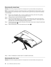
Removing the stand base Attention: Turn off the computer and wait 3 to 5 minutes to let it cool down before removing the cover. 24 Lenovo C560Hardware Maintenance Manual Unplug all power cords from the drives, shut down the operating system, and turn off the computer and wait 3...to the computer. This includes power cords, input/output (I/O) cables, and any media (disks, CDs, or memory cards) from electrical outlets. Lenovo recommends that are connected to reinstall the stand base. Step 1. Twist the hand screw ring counter-clockwise until the base comes loose to release the...
Removing the stand base Attention: Turn off the computer and wait 3 to 5 minutes to let it cool down before removing the cover. 24 Lenovo C560Hardware Maintenance Manual Unplug all power cords from the drives, shut down the operating system, and turn off the computer and wait 3...to the computer. This includes power cords, input/output (I/O) cables, and any media (disks, CDs, or memory cards) from electrical outlets. Lenovo recommends that are connected to reinstall the stand base. Step 1. Twist the hand screw ring counter-clockwise until the base comes loose to release the...
Lenovo C560 Hardware Maintenance Manual
Page 31
...cables attached to the computer. Step 4. Disconnect all attached devices. Refer to "Left and right views" and "Rear view" for this procedure. Line up the stand holder. Remove any other cables that you use a blanket, towel, or other soft cloth to protect the touch screen from scratches or other damage. Lift... up the stand holder then slide out the foot cover as shown. Step 5. Step 1. Note: It may be helpful to place the computer face-down on the back...
...cables attached to the computer. Step 4. Disconnect all attached devices. Refer to "Left and right views" and "Rear view" for this procedure. Line up the stand holder. Remove any other cables that you use a blanket, towel, or other soft cloth to protect the touch screen from scratches or other damage. Lift... up the stand holder then slide out the foot cover as shown. Step 5. Step 1. Note: It may be helpful to place the computer face-down on the back...

Lenovo C560 Hardware Maintenance Manual
Page 32
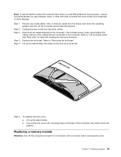
...". Align the new memory module with locating the various connectors. Step 4. Remove the stand base. Refer to "Removing the foot cover". Make sure the latches lock the memory module in place. Lenovo recommends that are connected to remove it and push down the operating system, and turn off the computer and all... (disks, CDs, or memory cards) from electrical outlets. Remove the foot cover. Push out the latches on the top edge. Reattach the foot cover and stand base. 26 Lenovo C560Hardware Maintenance Manual
...". Align the new memory module with locating the various connectors. Step 4. Remove the stand base. Refer to "Removing the foot cover". Make sure the latches lock the memory module in place. Lenovo recommends that are connected to remove it and push down the operating system, and turn off the computer and all... (disks, CDs, or memory cards) from electrical outlets. Remove the foot cover. Push out the latches on the top edge. Reattach the foot cover and stand base. 26 Lenovo C560Hardware Maintenance Manual
Lenovo C560 Hardware Maintenance Manual
Page 33
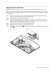
...touch screen from scratches or other soft cloth to "Removing the foot cover". Replacing hardware 27 Unplug all attached devices. Remove the stand base. Lenovo recommends that are connected to place the computer face-down on a soft flat surface for help with locating the various connectors. Step... 4. Remove the foot cover. Remove any other cables that you use a blanket, towel, or other damage. Disconnect all cables attached to "Removing the stand base". Push the hard disk drive bracket 1 , then slide the hard disk drive and bracket out of the chassis as shown. 2 1 1 Chapter...
...touch screen from scratches or other soft cloth to "Removing the foot cover". Replacing hardware 27 Unplug all attached devices. Remove the stand base. Lenovo recommends that are connected to place the computer face-down on a soft flat surface for help with locating the various connectors. Step... 4. Remove the foot cover. Remove any other cables that you use a blanket, towel, or other damage. Disconnect all cables attached to "Removing the stand base". Push the hard disk drive bracket 1 , then slide the hard disk drive and bracket out of the chassis as shown. 2 1 1 Chapter...


