
User Guide
Page 1
ThinkCentre User Guide Machine Types: 0399, 0452, 0500, 0598, and 0841
ThinkCentre User Guide Machine Types: 0399, 0452, 0500, 0598, and 0841

User Guide
Page 4
... pursuant a General Services Administration ″GSA″ contract, use, reproduction, or disclosure is subject to use, reproduction and disclosure. Second Edition (November 2009) © Copyright Lenovo 2009. GS-35F-05925. LIMITED AND RESTRICTED RIGHTS NOTICE: If products, data, computer software, or services are sold to governmental entities as commercial items as... rights to restrictions set forth in Contract No. Note Before using this information and the product it supports, be sure to read and understand the ThinkCentre Safety and Warranty Guide and "Notices," on page 55.
... pursuant a General Services Administration ″GSA″ contract, use, reproduction, or disclosure is subject to use, reproduction and disclosure. Second Edition (November 2009) © Copyright Lenovo 2009. GS-35F-05925. LIMITED AND RESTRICTED RIGHTS NOTICE: If products, data, computer software, or services are sold to governmental entities as commercial items as... rights to restrictions set forth in Contract No. Note Before using this information and the product it supports, be sure to read and understand the ThinkCentre Safety and Warranty Guide and "Notices," on page 55.
User Guide
Page 5
...drivers . . . . . 36 Chapter 4. Notices 55 Television output notice 56 Trademarks 56 Index 57 © Copyright Lenovo 2009 iii Installing or replacing hardware 13 Handling static-sensitive devices 13 Installing or replacing hardware 13 Installing external options 13 ...Optical mouse 47 Non-optical mouse 48 Chapter 7. Troubleshooting and diagnostics 45 Basic troubleshooting 45 Diagnostic programs 46 Lenovo ThinkVantage Toolbox 46 Lenovo System Toolbox 46 PC-Doctor for service 52 Using other services 53 Purchasing additional services 54 Appendix. Product overview...
...drivers . . . . . 36 Chapter 4. Notices 55 Television output notice 56 Trademarks 56 Index 57 © Copyright Lenovo 2009 iii Installing or replacing hardware 13 Handling static-sensitive devices 13 Installing or replacing hardware 13 Installing external options 13 ...Optical mouse 47 Non-optical mouse 48 Chapter 7. Troubleshooting and diagnostics 45 Basic troubleshooting 45 Diagnostic programs 46 Lenovo ThinkVantage Toolbox 46 Lenovo System Toolbox 46 PC-Doctor for service 52 Using other services 53 Purchasing additional services 54 Appendix. Product overview...

User Guide
Page 7
... damage to your product. Refer to the ThinkCentre Safety and Warranty Guide that you can obtain a Portable Document Format (PDF) version from the Lenovo® Support Web site at: http://www.lenovo.com/support © Copyright Lenovo 2009 v Reading and understanding this safety information... reduces the risk of the ThinkCentre Safety and Warranty Guide, you received with this product. ...
... damage to your product. Refer to the ThinkCentre Safety and Warranty Guide that you can obtain a Portable Document Format (PDF) version from the Lenovo® Support Web site at: http://www.lenovo.com/support © Copyright Lenovo 2009 v Reading and understanding this safety information... reduces the risk of the ThinkCentre Safety and Warranty Guide, you received with this product. ...
User Guide
Page 9
... covers a variety of models. See Chapter 4, "Using the Setup Utility," on startup v System Management (SM) Basic Input/Output System (BIOS) and SM software © Copyright Lenovo 2009 1 Chapter 1. Product overview Features This chapter provides information about the computer features. For information about your specific model, use the Setup Utility program.
... covers a variety of models. See Chapter 4, "Using the Setup Utility," on startup v System Management (SM) Basic Input/Output System (BIOS) and SM software © Copyright Lenovo 2009 1 Chapter 1. Product overview Features This chapter provides information about the computer features. For information about your specific model, use the Setup Utility program.
User Guide
Page 10
v Wake on LAN v Wake on Ring (in the Setup Utility program, this feature is called Serial Port Ring Detect for BIOS access Software programs, preinstalled Your computer might come with preinstalled software programs. If it does, an operating system, device drivers to support built-in Windows 7 Professional, Windows 7 Ultimate, Windows Vista Business, or Windows Vista Ultimate) 2 User Guide Operating system, preinstalled v Microsoft® Windows® 7 v Microsoft Windows Vista® v Microsoft Windows XP Professional (preinstalled through downgrade rights in features, and other support...
v Wake on LAN v Wake on Ring (in the Setup Utility program, this feature is called Serial Port Ring Detect for BIOS access Software programs, preinstalled Your computer might come with preinstalled software programs. If it does, an operating system, device drivers to support built-in Windows 7 Professional, Windows 7 Ultimate, Windows Vista Business, or Windows Vista Ultimate) 2 User Guide Operating system, preinstalled v Microsoft® Windows® 7 v Microsoft Windows Vista® v Microsoft Windows XP Professional (preinstalled through downgrade rights in features, and other support...

User Guide
Page 11
Dimensions Width: 175 mm (6.9 inches) Height: 371 mm (14.6 inches) (with front bezel) 350 mm (13.78 inches) (without front bezel) Depth: 425 mm (16.7 inches) (with front bezel) 370 mm (14.5 inches) (without front bezel) Weight Maximum configuration as shipped: 11.2 kg (24.7 lbs) Environment Air temperature: Operating: 10° to 35°C (50° to 95°F) Non-operating: -40° to 60°C (-40° to 140°F) (with package) Non-operating: -10° to 60°C (14° to 140°F) (without package) Humidity: Operating: 20% to 80% (10% per hour, non condensing) Non-...
Dimensions Width: 175 mm (6.9 inches) Height: 371 mm (14.6 inches) (with front bezel) 350 mm (13.78 inches) (without front bezel) Depth: 425 mm (16.7 inches) (with front bezel) 370 mm (14.5 inches) (without front bezel) Weight Maximum configuration as shipped: 11.2 kg (24.7 lbs) Environment Air temperature: Operating: 10° to 35°C (50° to 95°F) Non-operating: -40° to 60°C (-40° to 140°F) (with package) Non-operating: -10° to 60°C (14° to 140°F) (without package) Humidity: Operating: 20% to 80% (10% per hour, non condensing) Non-...
User Guide
Page 12
...various tools to help you keep the software on computers preinstalled with Windows Vista or Windows XP from Lenovo. Lenovo ThinkVantage Toolbox The Lenovo ThinkVantage Toolbox program helps you maintain your computer, improve computing security, diagnose computer problems, get more information...between system performance and power saving. Note: The Lenovo System Toolbox program is preinstalled on page 46 for your power settings to restore the contents of software that can adjust your ThinkCentre® computer. ThinkVantage System Update: The ThinkVantage System...
...various tools to help you keep the software on computers preinstalled with Windows Vista or Windows XP from Lenovo. Lenovo ThinkVantage Toolbox The Lenovo ThinkVantage Toolbox program helps you maintain your computer, improve computing security, diagnose computer problems, get more information...between system performance and power saving. Note: The Lenovo System Toolbox program is preinstalled on page 46 for your power settings to restore the contents of software that can adjust your ThinkCentre® computer. ThinkVantage System Update: The ThinkVantage System...
User Guide
Page 13
... a full version of antivirus software on page 51 for more information about accessing the online books and the Lenovo Web site. See "Online Books folder" on your antivirus software, refer to continue receiving the antivirus program updates. Antivirus software Your computer comes with a free ...
... a full version of antivirus software on page 51 for more information about accessing the online books and the Lenovo Web site. See "Online Books folder" on your antivirus software, refer to continue receiving the antivirus program updates. Antivirus software Your computer comes with a free ...

User Guide
Page 14
Figure 1. Front connector locations 1 USB connector 2 Headphone connector 3 Microphone connector 4 USB connector 6 User Guide Note: Not all computer models have the following connectors. Locations Locating connectors on the front of your computer Figure 1 shows the locations of the connectors on the front of your computer.
Figure 1. Front connector locations 1 USB connector 2 Headphone connector 3 Microphone connector 4 USB connector 6 User Guide Note: Not all computer models have the following connectors. Locations Locating connectors on the front of your computer Figure 1 shows the locations of the connectors on the front of your computer.

User Guide
Page 15
Locating connectors on the rear of your computer Figure 2 shows the locations of the connectors on the rear of your computer are color-coded to help you determine where to connect the cables on the rear of your computer. Product overview 7 Some connectors on your computer. Rear connector locations 1 Voltage-selection switch 2 Power cord connector 3 Serial port 4 VGA monitor connector 5 USB connectors (4) 6 Microphone connector 7 Audio line-out connector 8 Audio line-in connector 9 PCI Express x16 graphics card slot 10 PCI Express x1 card slot 11 PCI card slots (2) 12 Serial port (...
Locating connectors on the rear of your computer Figure 2 shows the locations of the connectors on the rear of your computer are color-coded to help you determine where to connect the cables on the rear of your computer. Product overview 7 Some connectors on your computer. Rear connector locations 1 Voltage-selection switch 2 Power cord connector 3 Serial port 4 VGA monitor connector 5 USB connectors (4) 6 Microphone connector 7 Audio line-out connector 8 Audio line-in connector 9 PCI Express x16 graphics card slot 10 PCI Express x1 card slot 11 PCI card slots (2) 12 Serial port (...

User Guide
Page 16
Microphone connector Used to attach a microphone to your computer when you use speech-recognition software. Ethernet connector Used to record sound or if you want to attach an Ethernet cable for a local area network (LAN). Note: To operate the computer within FCC Class B limits, use to receive audio signals from the computer to attach a device that requires a USB connector, such as a stereo system. USB connector Used to external devices, such as powered stereo speakers (speakers with built-in amplifiers), headphones, multimedia keyboards, the audio line-in connector ...
Microphone connector Used to attach a microphone to your computer when you use speech-recognition software. Ethernet connector Used to record sound or if you want to attach an Ethernet cable for a local area network (LAN). Note: To operate the computer within FCC Class B limits, use to receive audio signals from the computer to attach a device that requires a USB connector, such as a stereo system. USB connector Used to external devices, such as powered stereo speakers (speakers with built-in amplifiers), headphones, multimedia keyboards, the audio line-in connector ...
User Guide
Page 17
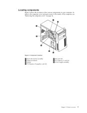
Figure 3. Component locations 1 Heat sink and fan assembly 2 Memory modules 3 Battery 4 PCI Express x16 graphics card slot 5 PCI card slot 6 PCI Express x1 card slot 7 Power supply assembly Chapter 1. Product overview 9 Locating components Figure 3 shows the locations of the computer, see "Removing the computer cover" on page 14. To remove the computer cover and gain access to the inside of the various components in your computer.
Figure 3. Component locations 1 Heat sink and fan assembly 2 Memory modules 3 Battery 4 PCI Express x16 graphics card slot 5 PCI card slot 6 PCI Express x1 card slot 7 Power supply assembly Chapter 1. Product overview 9 Locating components Figure 3 shows the locations of the computer, see "Removing the computer cover" on page 14. To remove the computer cover and gain access to the inside of the various components in your computer.
User Guide
Page 18
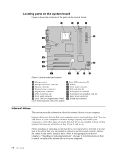
Locating parts on the system board Figure 4 shows the locations of media. You can install or replace in bays. Figure 4. System board part locations 1 Microprocessor 2 Microprocessor fan connector 3 Memory slots (2) 4 Thermal sensor connector 5 24-pin power connector 6 SATA connectors (3) 7 Front panel connector 8 Clear CMOS (Complementary Metal Oxide Semiconductor) /Recovery jumper 9 Front USB connectors (2) 10 Battery 11 Front audio connector 12 PCI card slots (2) 13 PCI Express x1 card slot 14 PCI Express x16 graphics card slot 15 4-pin power connector 16 System fan connector ...
Locating parts on the system board Figure 4 shows the locations of media. You can install or replace in bays. Figure 4. System board part locations 1 Microprocessor 2 Microprocessor fan connector 3 Memory slots (2) 4 Thermal sensor connector 5 24-pin power connector 6 SATA connectors (3) 7 Front panel connector 8 Clear CMOS (Complementary Metal Oxide Semiconductor) /Recovery jumper 9 Front USB connectors (2) 10 Battery 11 Front audio connector 12 PCI card slots (2) 13 PCI Express x1 card slot 14 PCI Express x16 graphics card slot 15 4-pin power connector 16 System fan connector ...

User Guide
Page 19
Optical drive bay (with a 3.5-inch SATA hard disk drive installed) Chapter 1. Primary SATA hard disk drive bay (with an optical drive installed) 2 Bay 2 - Figure 5. Drive bay locations 1 Bay 1 - Figure 5 shows the locations of the drive bays in your computer. Product overview 11 Secondary SATA hard disk drive bay 3 Bay 3 -
Optical drive bay (with a 3.5-inch SATA hard disk drive installed) Chapter 1. Primary SATA hard disk drive bay (with an optical drive installed) 2 Bay 2 - Figure 5. Drive bay locations 1 Bay 1 - Figure 5 shows the locations of the drive bays in your computer. Product overview 11 Secondary SATA hard disk drive bay 3 Bay 3 -
User Guide
Page 21
... new part on a smooth, level surface, and then place the new part on the computer for the option. © Copyright Lenovo 2009 13 v Do not place the part on the computer cover or other computer components carefully. Use only computer parts provided by the...computer components. When you must install additional software in the computer without setting it . Handle memory modules, PCI cards, system boards, and microprocessors by Lenovo. 2. Installing or replacing hardware This section provides instructions on page 7 to your computer, such as external speakers, a printer, or a scanner....
... new part on a smooth, level surface, and then place the new part on the computer for the option. © Copyright Lenovo 2009 13 v Do not place the part on the computer cover or other computer components carefully. Use only computer parts provided by the...computer components. When you must install additional software in the computer without setting it . Handle memory modules, PCI cards, system boards, and microprocessors by Lenovo. 2. Installing or replacing hardware This section provides instructions on page 7 to your computer, such as external speakers, a printer, or a scanner....
User Guide
Page 22
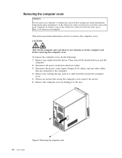
...computer cover, remove the screws. 6. Removing the computer cover 14 User Guide To obtain a copy of the ThinkCentre Safety and Warranty Guide, go to: http://www.lenovo.com/support This section provides instructions on how to the rear. If there are screws that are connected to ...let the computer cool before reading and understanding the "Important safety information" in the ThinkCentre Safety and Warranty Guide that secures the...
...computer cover, remove the screws. 6. Removing the computer cover 14 User Guide To obtain a copy of the ThinkCentre Safety and Warranty Guide, go to: http://www.lenovo.com/support This section provides instructions on how to the rear. If there are screws that are connected to ...let the computer cool before reading and understanding the "Important safety information" in the ThinkCentre Safety and Warranty Guide that secures the...
User Guide
Page 23
... or attempt any repair before reading and understanding the "Important safety information" in the ThinkCentre Safety and Warranty Guide that came with your computer. To obtain a copy of the ThinkCentre Safety and Warranty Guide, go to: http://www.lenovo.com/support This section provides instructions on how to the side without disconnecting the...
... or attempt any repair before reading and understanding the "Important safety information" in the ThinkCentre Safety and Warranty Guide that came with your computer. To obtain a copy of the ThinkCentre Safety and Warranty Guide, go to: http://www.lenovo.com/support This section provides instructions on how to the side without disconnecting the...

User Guide
Page 24
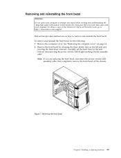
3. Figure 8. Reinstalling the front bezel 4. To reinstall the front bezel, align the plastic tabs on the left side. Then, pivot the front bezel inward until it snaps into position on the right side of the front bezel with the corresponding holes in the chassis. Note: If you have completely removed the front bezel off the chassis, you need to "Completing the parts replacement" on page 31. 16 User Guide Go to first route and connect the power switch/LED assembly cable.
3. Figure 8. Reinstalling the front bezel 4. To reinstall the front bezel, align the plastic tabs on the left side. Then, pivot the front bezel inward until it snaps into position on the right side of the front bezel with the corresponding holes in the chassis. Note: If you have completely removed the front bezel off the chassis, you need to "Completing the parts replacement" on page 31. 16 User Guide Go to first route and connect the power switch/LED assembly cable.
User Guide
Page 25
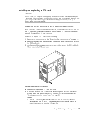
...moving each side of your computer. Remove any parts and disconnect any repair before reading and understanding the "Important safety information" in the ThinkCentre Safety and Warranty Guide that came with your access to install or replace a PCI card. If you are replacing a PCI card, ...a. Installing or replacing hardware 17 See "Removing the computer cover" on page 10. At the rear of the ThinkCentre Safety and Warranty Guide, go to: http://www.lenovo.com/support This section provides instructions on the system board and remove the old PCI card that is completely removed ...
...moving each side of your computer. Remove any parts and disconnect any repair before reading and understanding the "Important safety information" in the ThinkCentre Safety and Warranty Guide that came with your access to install or replace a PCI card. If you are replacing a PCI card, ...a. Installing or replacing hardware 17 See "Removing the computer cover" on page 10. At the rear of the ThinkCentre Safety and Warranty Guide, go to: http://www.lenovo.com/support This section provides instructions on the system board and remove the old PCI card that is completely removed ...