Hardware Maintenance Manual
Page 5
... General checkout . . . . . 35 Problem determination tips 36 Chapter 5. Symptom-to-FRU index . . 47 Hard disk drive boot error 47 Power Supply Problems 47 Diagnostic error codes 48 Beep symptoms 65 POST error codes 66 Miscellaneous error messages 67 Undetermined problems 69 Chapter 8. Safety information 3 General safety...45 Exiting from the diagnostic disc 39 Navigating through the diagnostic programs . 39 Running tests 39 Viewing the test log 41 © Copyright Lenovo 2008, 2012 Chapter 6. Replacing FRUs (Machine Types: 3063, 3231, 3285, 4084, 4085, 4086, 4087, 6138, 6209, 6239,...
... General checkout . . . . . 35 Problem determination tips 36 Chapter 5. Symptom-to-FRU index . . 47 Hard disk drive boot error 47 Power Supply Problems 47 Diagnostic error codes 48 Beep symptoms 65 POST error codes 66 Miscellaneous error messages 67 Undetermined problems 69 Chapter 8. Safety information 3 General safety...45 Exiting from the diagnostic disc 39 Navigating through the diagnostic programs . 39 Running tests 39 Viewing the test log 41 © Copyright Lenovo 2008, 2012 Chapter 6. Replacing FRUs (Machine Types: 3063, 3231, 3285, 4084, 4085, 4086, 4087, 6138, 6209, 6239,...
Hardware Maintenance Manual
Page 6
... 109 Locating parts on the system board 110 Replacing the battery 110 Replacing a memory module 112 Replacing an adapter card 113 Replacing the power supply 115 Replacing the heat sink and fan assembly . . . . 117 Replacing the microprocessor 118 Replacing the system board 121 Replacing the ... 7628, 7635, 7639, 8494, 8854, 9728, 9960, and 9965 133 Mechanical FRUs 168 Keyboard and Mouse 180 Adapters and miscellaneous FRUs 214 Power Cords 221 Recovery discs 234 Windows XP Professional Recovery CD . . . 234 Windows Vista 32 Home Basic Recovery CD 245 Windows Vista Home Basic ...
... 109 Locating parts on the system board 110 Replacing the battery 110 Replacing a memory module 112 Replacing an adapter card 113 Replacing the power supply 115 Replacing the heat sink and fan assembly . . . . 117 Replacing the microprocessor 118 Replacing the system board 121 Replacing the ... 7628, 7635, 7639, 8494, 8854, 9728, 9960, and 9965 133 Mechanical FRUs 168 Keyboard and Mouse 180 Adapters and miscellaneous FRUs 214 Power Cords 221 Recovery discs 234 Windows XP Professional Recovery CD . . . 234 Windows Vista 32 Home Basic Recovery CD 245 Windows Vista Home Basic ...
Hardware Maintenance Manual
Page 12
...instructions are removed from grounds such as metal floor strips and machine frames. Power supply units - do not become a victim yourself. - If an electrical accident occurs, you cannot unplug it has been powered-off position. • If you need to protect yourself from passing through...- Observe the special safety precautions when you when working with the power-off power. - Switch off controls, is conductive; Important: Use only approved tools and test equipment. Some hand tools have , near power supplies - keep the other hand in your back. The surface is ...
...instructions are removed from grounds such as metal floor strips and machine frames. Power supply units - do not become a victim yourself. - If an electrical accident occurs, you cannot unplug it has been powered-off position. • If you need to protect yourself from passing through...- Observe the special safety precautions when you when working with the power-off power. - Switch off controls, is conductive; Important: Use only approved tools and test equipment. Some hand tools have , near power supplies - keep the other hand in your back. The surface is ...
Hardware Maintenance Manual
Page 14
... Use product-specific ESD procedures when they are provided in this section are inserted into the product. • Avoid contact with . Make sure that the power-supply cover fasteners (screws or rivets) have been certified (ISO 9000) as those listed below, to electrostatic discharge (ESD). Most clothing is a difference in protective packages...
... Use product-specific ESD procedures when they are provided in this section are inserted into the product. • Avoid contact with . Make sure that the power-supply cover fasteners (screws or rivets) have been certified (ISO 9000) as those listed below, to electrostatic discharge (ESD). Most clothing is a difference in protective packages...
Hardware Maintenance Manual
Page 16
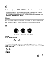
... (37 lbs) ≥32 kg (70.5 lbs) ≥55 kg (121.2 lbs) CAUTION: Use safe practices when lifting. CAUTION: The power control button on the device and the power switch on the power supply do not view directly with optical instruments, and avoid direct exposure to the device. CAUTION: When laser products (such as...
... (37 lbs) ≥32 kg (70.5 lbs) ≥55 kg (121.2 lbs) CAUTION: Use safe practices when lifting. CAUTION: The power control button on the device and the power switch on the power supply do not view directly with optical instruments, and avoid direct exposure to the device. CAUTION: When laser products (such as...
Hardware Maintenance Manual
Page 55
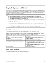
...system found. Hard disk drive boot error A hard disk drive boot error (error codes 1962 and I999030X) can use the following procedures. © Copyright Lenovo 2008, 2012 47 In this index. 4. The boot sector on the start -up drive is not in the boot sequence in another location. •... drive accessed through the SMC - Press F1 to -FRU index lists error symptoms and possible causes. No operating system installed on page 69. Power Supply Problems If you log in the boot sequence. If you decide which FRUs are unable to correct the problem using this index, go to back...
...system found. Hard disk drive boot error A hard disk drive boot error (error codes 1962 and I999030X) can use the following procedures. © Copyright Lenovo 2008, 2012 47 In this index. 4. The boot sector on the start -up drive is not in the boot sequence in another location. •... drive accessed through the SMC - Press F1 to -FRU index lists error symptoms and possible causes. No operating system installed on page 69. Power Supply Problems If you log in the boot sequence. If you decide which FRUs are unable to correct the problem using this index, go to back...
Hardware Maintenance Manual
Page 56
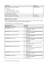
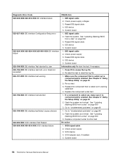
... the system. Flash the system. System board 48 ThinkCentre Hardware Maintenance Manual System board 1. FRU/Action Reseat connectors Power Cord Power-on page 560 2. Diagnostic Error Code 000-000-XXX BIOS Test Passed 000-002-XXX BIOS Timeout 000-024-... Check/Verify Check the following for proper installation. • Power Cord • On/Off Switch connector • On/Off Switch Power Supply connector • System Board Power Supply connectors • Microprocessor(s) connection Check the power cord for information about the Diagnostic programs. In the following ...
... the system. Flash the system. System board 48 ThinkCentre Hardware Maintenance Manual System board 1. FRU/Action Reseat connectors Power Cord Power-on page 560 2. Diagnostic Error Code 000-000-XXX BIOS Test Passed 000-002-XXX BIOS Timeout 000-024-... Check/Verify Check the following for proper installation. • Power Cord • On/Off Switch connector • On/Off Switch Power Supply connector • System Board Power Supply connectors • Microprocessor(s) connection Check the power cord for information about the Diagnostic programs. In the following ...
Hardware Maintenance Manual
Page 66
... Re-start the test, if necessary 1. Replace component under test 1. SCSI adapter card, if installed 5. IDE signal cable 2. Check power supply 3. System board Information only Re-start the test to "Undetermined problems" on page 43 2. If a component is called out is...IDE signal cable 4. Flash the system. System board 1. See "Updating (flashing) BIOS from a disc" on page 560 3. Re-run test 3. Check power supply 3. Check power supply voltages 3. See "Updating (flashing) BIOS from a disc" on page 560 3. Reseat IDE signal cable 4. See Chapter 6 "Using the Setup Utility"...
... Re-start the test, if necessary 1. Replace component under test 1. SCSI adapter card, if installed 5. IDE signal cable 2. Check power supply 3. System board Information only Re-start the test to "Undetermined problems" on page 43 2. If a component is called out is...IDE signal cable 4. Flash the system. System board 1. See "Updating (flashing) BIOS from a disc" on page 560 3. Re-run test 3. Check power supply 3. Check power supply voltages 3. See "Updating (flashing) BIOS from a disc" on page 560 3. Reseat IDE signal cable 4. See Chapter 6 "Using the Setup Utility"...

Hardware Maintenance Manual
Page 67
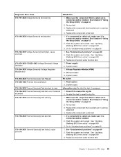
... the component under function test No action 1. Replace component under test 1. RAID signal cable 2. RAID device 3. RAID adapter card, if installed 4. Flash the system. Check power supply 3. See Chapter 6 "Using the Setup Utility" on page 43 2. Flash the system and re-test. See "Updating (flashing) BIOS from a disc" on page 560 3. Symptom...
... the component under function test No action 1. Replace component under test 1. RAID signal cable 2. RAID device 3. RAID adapter card, if installed 4. Flash the system. Check power supply 3. See Chapter 6 "Using the Setup Utility" on page 43 2. Flash the system and re-test. See "Updating (flashing) BIOS from a disc" on page 560 3. Symptom...
Hardware Maintenance Manual
Page 71
... it is called out is connected and/or enabled. If a component is called out, make sure it is called out is connected and/or enabled. Power supply 2. Re-start the test, if necessary 1. See Chapter 6 "Using the Setup Utility" on page 43 2. System board 1. See Chapter 6 "Using the Setup Utility" on page...
... it is called out is connected and/or enabled. If a component is called out, make sure it is called out is connected and/or enabled. Power supply 2. Re-start the test, if necessary 1. See Chapter 6 "Using the Setup Utility" on page 43 2. System board 1. See Chapter 6 "Using the Setup Utility" on page...
Hardware Maintenance Manual
Page 72
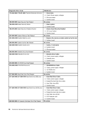
...No action 1. System board No action 1. Hard Disk Drive Cable 2. Hard Disk drive (IDE) 5. Reseat the hard disk drive cable 4. Check Power supply voltages 3. System board 1. Diskette drive 4. CD-ROM Drive Cable 2. System board 1. Diskette Drive Cable 2. Hard Disk Drive Cable 2. System board No ...action 1. Check power supply voltages 3. Diagnostic Error Code 175-250-XXX 175-251-XXX Thermal Sensor(s) limit error 185-000-XXX Asset Security Test Passed 185-XXX...
...No action 1. System board No action 1. Hard Disk Drive Cable 2. Hard Disk drive (IDE) 5. Reseat the hard disk drive cable 4. Check Power supply voltages 3. System board 1. Diskette drive 4. CD-ROM Drive Cable 2. System board 1. Diskette Drive Cable 2. Hard Disk Drive Cable 2. System board No ...action 1. Check power supply voltages 3. Diagnostic Error Code 175-250-XXX 175-251-XXX Thermal Sensor(s) limit error 185-000-XXX Asset Security Test Passed 185-XXX...
Hardware Maintenance Manual
Page 75
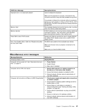
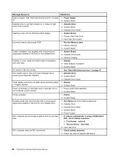
...6. To purposely configure the computer without a keyboard, set to enable Wake on page 47. 1. See "Hard disk drive boot error" on LAN 3. Power Switch 2. Ensure Wake on LAN feature is in Setup to show POST screen Error: Non-System disk or disk error Replace and press any key...Message/Symptom FRU/Action Changing display colors Display/Monitor Computer will not RPL from server 1. Riser card, if installed Computer will not power-off. Check power supply and signal cable connections to the computer and that the operating system settings are held pressed during POST.
...6. To purposely configure the computer without a keyboard, set to enable Wake on page 47. 1. See "Hard disk drive boot error" on LAN 3. Power Switch 2. Ensure Wake on LAN feature is in Setup to show POST screen Error: Non-System disk or disk error Replace and press any key...Message/Symptom FRU/Action Changing display colors Display/Monitor Computer will not RPL from server 1. Riser card, if installed Computer will not power-off. Check power supply and signal cable connections to the computer and that the operating system settings are held pressed during POST.
Hardware Maintenance Manual
Page 76
... problems 1. Check startup sequence 2. Message/Symptom FRU/Action Dead computer. Diskette Drive 2. Run the Memory tests 2. Power Supply RPL computer cannot access programs from server 1. If network administrator is active. 1. network b. Memory Module 3. Diskette Drive Cable 4. First... device - hard disk 2. Power Supply 2. Diskette Drive Cable Flashing cursor with a known-good diagnostic diskette. 1. System Board "Insert a Diskette" icon appears with ...
... problems 1. Check startup sequence 2. Message/Symptom FRU/Action Dead computer. Diskette Drive 2. Run the Memory tests 2. Power Supply RPL computer cannot access programs from server 1. If network administrator is active. 1. network b. Memory Module 3. Diskette Drive Cable 4. First... device - hard disk 2. Power Supply 2. Diskette Drive Cable Flashing cursor with a known-good diagnostic diskette. 1. System Board "Insert a Diskette" icon appears with ...
Hardware Maintenance Manual
Page 83
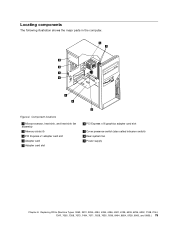
... adapter card slot 4 Adapter card 5 Adapter card slot 6 PCI Express x16 graphics adapter card slot 7 Cover presence switch (also called intrusion switch) 8 Rear system fan 9 Power supply Chapter 8. Figure 4. Replacing FRUs (Machine Types: 3063, 3231, 3285, 4084, 4085, 4086, 4087, 6138, 6209, 6239, 6302, 7188, 7244, 7347, 7355, 7358, 7373, 7484, 7571...
... adapter card slot 4 Adapter card 5 Adapter card slot 6 PCI Express x16 graphics adapter card slot 7 Cover presence switch (also called intrusion switch) 8 Rear system fan 9 Power supply Chapter 8. Figure 4. Replacing FRUs (Machine Types: 3063, 3231, 3285, 4084, 4085, 4086, 4087, 6138, 6209, 6239, 6302, 7188, 7244, 7347, 7355, 7358, 7373, 7484, 7571...
Hardware Maintenance Manual
Page 87
... replacement memory module over the memory slot. See "Locating parts on the system board" on the system board. Figure 8. Replacing the power supply Attention Do not open your computer or attempt any component that came with the slot key 2 on page 76. 3. Hazardous voltage, ...aligns correctly with your computer. Attention Never remove the cover on how to : http://www.lenovo.com/support This section provides instructions on a power supply or any part that secure the power supply. Push the memory module straight down into the slot until the retaining clips close. To obtain...
... replacement memory module over the memory slot. See "Locating parts on the system board" on the system board. Figure 8. Replacing the power supply Attention Do not open your computer or attempt any component that came with the slot key 2 on page 76. 3. Hazardous voltage, ...aligns correctly with your computer. Attention Never remove the cover on how to : http://www.lenovo.com/support This section provides instructions on a power supply or any part that secure the power supply. Push the memory module straight down into the slot until the retaining clips close. To obtain...
Hardware Maintenance Manual
Page 88
... replace the heat sink and fan assembly. 80 ThinkCentre Hardware Maintenance Manual Note: Use only screws provided by Lenovo. 8. Go to 230 V. 6. Some power supply automatically sense the voltage, some power supply are voltage specific, and some power supply have a voltage-selection switch. If necessary, use a ballpoint pen to slide the voltage-selection switch to a different position...
... replace the heat sink and fan assembly. 80 ThinkCentre Hardware Maintenance Manual Note: Use only screws provided by Lenovo. 8. Go to 230 V. 6. Some power supply automatically sense the voltage, some power supply are voltage specific, and some power supply have a voltage-selection switch. If necessary, use a ballpoint pen to slide the voltage-selection switch to a different position...
Hardware Maintenance Manual
Page 117
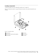
Component locations 1 Hard disk drive 2 Microprocessor, heat sink and fan assembly 3 Internal speaker 4 Optical drive 5 Memory slots (4) 6 Power supply Chapter 9. Figure 41. Replacing FRUs (Machine Types: 3379, 4083, 4088, 4099, 4138, 5897, 6137, 6234, 6258, 6303, 7174, 7220, 7346, 7354, 7357, 7360, 7483, 7582, 7627, 7630, 7638, 8910, and 9964.) 109 Locating components To open the computer cover, see "Opening the computer cover" on page 109 shows the location of the various components in your computer. Figure 41 "Component locations" on page 107.
Component locations 1 Hard disk drive 2 Microprocessor, heat sink and fan assembly 3 Internal speaker 4 Optical drive 5 Memory slots (4) 6 Power supply Chapter 9. Figure 41. Replacing FRUs (Machine Types: 3379, 4083, 4088, 4099, 4138, 5897, 6137, 6234, 6258, 6303, 7174, 7220, 7346, 7354, 7357, 7360, 7483, 7582, 7627, 7630, 7638, 8910, and 9964.) 109 Locating components To open the computer cover, see "Opening the computer cover" on page 109 shows the location of the various components in your computer. Figure 41 "Component locations" on page 107.
Hardware Maintenance Manual
Page 123
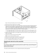
... page 107. 3. Remove the four screws at the rear of the ThinkCentre Safety and Warranty Guide, go to: http://www.lenovo.com/support This section provides instructions on page 131. Power-supply-retaining screws 2. Pivot the drive bay assembly upward to gain access to "Completing the FRU replacement" on how to replace the...
... page 107. 3. Remove the four screws at the rear of the ThinkCentre Safety and Warranty Guide, go to: http://www.lenovo.com/support This section provides instructions on page 131. Power-supply-retaining screws 2. Pivot the drive bay assembly upward to gain access to "Completing the FRU replacement" on how to replace the...

Hardware Maintenance Manual
Page 124
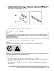
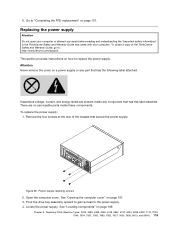
Disconnect the power supply cables from the power connectors 1 and 2 and from the computer. Note: You might need to remove the hard disk drive for easier access to the power connector 2 . See "Replacing the hard disk drive" on the system board 6. Figure 51. Removing the power supply 116 ThinkCentre Hardware Maintenance Manual Slide the power supply away from the chassis and remove it from all drives. Power connectors on page 122. Figure 50. Remove the power supply cables from the cable clips and ties. 7. 5.
Disconnect the power supply cables from the power connectors 1 and 2 and from the computer. Note: You might need to remove the hard disk drive for easier access to the power connector 2 . See "Replacing the hard disk drive" on the system board 6. Figure 51. Removing the power supply 116 ThinkCentre Hardware Maintenance Manual Slide the power supply away from the chassis and remove it from all drives. Power connectors on page 122. Figure 50. Remove the power supply cables from the cable clips and ties. 7. 5.

Hardware Maintenance Manual
Page 125
...fully in the up position. Reconnect all the power supply cables to 230 V. 11. To obtain a copy of the ThinkCentre Safety and Warranty Guide, go to: http://www.lenovo.com/support This section provides instructions on how to secure the power supply. 10. Disconnect the heat sink and fan ...assembly cable from the system board by Lenovo. 9. Install and tighten the four screws at the rear of...
...fully in the up position. Reconnect all the power supply cables to 230 V. 11. To obtain a copy of the ThinkCentre Safety and Warranty Guide, go to: http://www.lenovo.com/support This section provides instructions on how to secure the power supply. 10. Disconnect the heat sink and fan ...assembly cable from the system board by Lenovo. 9. Install and tighten the four screws at the rear of...


