Hardware Maintenance Manual
Page 5
... 5. Portions © IBM Corp. 2005. Symptom-to-FRU Index . . . 53 Hard disk drive boot error 53 © Lenovo 2005, 2008. Contents Chapter 1. Diagnostics 43 PC-Doctor for Windows 43 PC-Doctor for Windows PE 43 Running diagnostics from the Rescue ...6072, 6073, 6077, 6078, 6087, 6088, 9181, and 9196) 83 Locations 84 Front connectors 84 Rear connectors 85 Computer components 86 System board connectors 87 Opening the cover 88 Accessing system board components and drives . . 89 Replacing an adapter card 90 Replacing a memory module 91 Replacing the battery 93 Replacing the power supply...
... 5. Portions © IBM Corp. 2005. Symptom-to-FRU Index . . . 53 Hard disk drive boot error 53 © Lenovo 2005, 2008. Contents Chapter 1. Diagnostics 43 PC-Doctor for Windows 43 PC-Doctor for Windows PE 43 Running diagnostics from the Rescue ...6072, 6073, 6077, 6078, 6087, 6088, 9181, and 9196) 83 Locations 84 Front connectors 84 Rear connectors 85 Computer components 86 System board connectors 87 Opening the cover 88 Accessing system board components and drives . . 89 Replacing an adapter card 90 Replacing a memory module 91 Replacing the battery 93 Replacing the power supply...
Hardware Maintenance Manual
Page 10
...shock. Removing or installing Field Replaceable Units v Before you may prevent a current from a circuit. If you . Ensure that supplies power to the machine and to switch off the power, if necessary. - Remember: Another person must be hazardous. Many customers have handles covered with live electrical currents. Remember: ...wall box in the safety sections of mat to insulate you need to work alone under hazardous conditions or near power supplies - CAUTION: Electrical current from power, telephone, and communication cables can then operate the switch or unplug the...
...shock. Removing or installing Field Replaceable Units v Before you may prevent a current from a circuit. If you . Ensure that supplies power to the machine and to switch off the power, if necessary. - Remember: Another person must be hazardous. Many customers have handles covered with live electrical currents. Remember: ...wall box in the safety sections of mat to insulate you need to work alone under hazardous conditions or near power supplies - CAUTION: Electrical current from power, telephone, and communication cables can then operate the switch or unplug the...
Hardware Maintenance Manual
Page 11
...good condition. Power supply units - Pumps - do not become a victim yourself. - Each machine, as it was designed and built, had required safety items installed to assist you in the parts listings. Disconnect the power cord. 3. Use a meter to get medical aid. The power cord should...external ground pin and frame ground. If any unsafe conditions are removed from injury. Consider these hazards are moist floors, nongrounded power extension cables, power surges, and missing safety grounds. Checklist: 1. c. such touching can continue without first correcting the problem. v Do not ...
...good condition. Power supply units - Pumps - do not become a victim yourself. - Each machine, as it was designed and built, had required safety items installed to assist you in the parts listings. Disconnect the power cord. 3. Use a meter to get medical aid. The power cord should...external ground pin and frame ground. If any unsafe conditions are removed from injury. Consider these hazards are moist floors, nongrounded power extension cables, power surges, and missing safety grounds. Checklist: 1. c. such touching can continue without first correcting the problem. v Do not ...
Hardware Maintenance Manual
Page 12
... handling ESD-sensitive parts: v Keep the parts in charge between objects. v Prevent the part from touching your skin to any alterations. 6. Make sure that the power-supply cover fasteners (screws or rivets) have been certified (ISO 9000) as metal filings, contamination, water or other people. Most clothing is required for any obvious...
... handling ESD-sensitive parts: v Keep the parts in charge between objects. v Prevent the part from touching your skin to any alterations. 6. Make sure that the power-supply cover fasteners (screws or rivets) have been certified (ISO 9000) as metal filings, contamination, water or other people. Most clothing is required for any obvious...
Hardware Maintenance Manual
Page 15
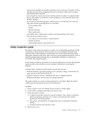
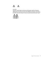
CAUTION: The power control button on the device and the power switch on the power supply do not turn off the electrical current supplied to the device. To remove all electrical current from the device, ensure that all power cords are disconnected from the power source. 2 1 Chapter 2. The device also might have more than one power cord. Safety information 9
CAUTION: The power control button on the device and the power switch on the power supply do not turn off the electrical current supplied to the device. To remove all electrical current from the device, ensure that all power cords are disconnected from the power source. 2 1 Chapter 2. The device also might have more than one power cord. Safety information 9
Hardware Maintenance Manual
Page 59
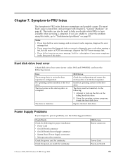
... the boot sequence. Attempt to correct the problem using this index. v Power Cord v On/Off Switch connector v On/Off Switch Power Supply connector v System Board Power Supply connectors v Microprocessor(s) connection Check the power cord for a description of this index, go to -FRU index lists ...2005. 53 Chapter 7. The boot sector on the boot drive. Install an operating system on Switch © Lenovo 2005, 2008. Replace the hard disk drive. Power Supply Problems If you did receive a POST error message, diagnose the POST error message first. Check/Verify Check the...
... the boot sequence. Attempt to correct the problem using this index. v Power Cord v On/Off Switch connector v On/Off Switch Power Supply connector v System Board Power Supply connectors v Microprocessor(s) connection Check the power cord for a description of this index, go to -FRU index lists ...2005. 53 Chapter 7. The boot sector on the boot drive. Install an operating system on Switch © Lenovo 2005, 2008. Replace the hard disk drive. Power Supply Problems If you did receive a POST error message, diagnose the POST error message first. Check/Verify Check the...
Hardware Maintenance Manual
Page 72
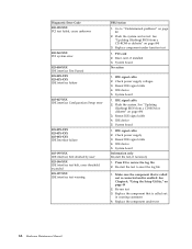
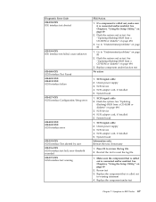
... problems" on page 494 3. Replace the component that is connected and/or enabled. Go to reset the log file 1. Check power supply voltages 3. Make sure the component that is called out is called out in warning statement 4. Replace the component under function test ...device 5. IDE device 5. Reseat IDE signal cable 4. IDE device 5. Replace component under test 66 Hardware Maintenance Manual Reseat IDE signal cable 4. Check power supply 3. See Chapter 6, "Using the Setup Utility," on page 494 3. System board No action 1. Reseat IDE signal cable 4. Press F3 to ...
... problems" on page 494 3. Replace the component that is connected and/or enabled. Go to reset the log file 1. Check power supply voltages 3. Make sure the component that is called out is called out in warning statement 4. Replace the component under function test ...device 5. IDE device 5. Reseat IDE signal cable 4. IDE device 5. Replace component under test 66 Hardware Maintenance Manual Reseat IDE signal cable 4. Check power supply 3. See Chapter 6, "Using the Setup Utility," on page 494 3. System board No action 1. Reseat IDE signal cable 4. Press F3 to ...
Hardware Maintenance Manual
Page 73
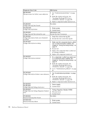
... 1. Make sure the component that is called out in warning statement 4. If a component is called out is connected and/or enabled. Check power supply 3. SCSI device 4. Re-run test 3. Flash the system and re-test. Replace the component that is called out, make sure it is... connected and/or enabled. System board 1. Check power supply 3. Go to "Undetermined problems" on page 80 2. Go to "Undetermined problems" on page 49 2. Diagnostic Error Code 025-198-XXX IDE ...
... 1. Make sure the component that is called out in warning statement 4. If a component is called out is connected and/or enabled. Check power supply 3. SCSI device 4. Re-run test 3. Flash the system and re-test. Replace the component that is called out, make sure it is... connected and/or enabled. System board 1. Check power supply 3. Go to "Undetermined problems" on page 80 2. Go to "Undetermined problems" on page 49 2. Diagnostic Error Code 025-198-XXX IDE ...
Hardware Maintenance Manual
Page 78
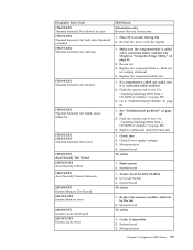
...-start the test, if necessary 170-196-XXX Voltage Sensor(s) test halt, error threshold exceeded 1. Make sure the component that is connected and/or enabled. Power supply 2. System board 175-000-XXX Thermal Sensor(s) Test Passed No action 175-0XX-XXX Thermal Sensor(s) failure 1. Diagnostic Error Code FRU/Action 089-199-XXX...
...-start the test, if necessary 170-196-XXX Voltage Sensor(s) test halt, error threshold exceeded 1. Make sure the component that is connected and/or enabled. Power supply 2. System board 175-000-XXX Thermal Sensor(s) Test Passed No action 175-0XX-XXX Thermal Sensor(s) failure 1. Diagnostic Error Code FRU/Action 089-199-XXX...
Hardware Maintenance Manual
Page 79
... Passed 202-XXX-XXX System Cache error FRU/Action Information only Re-start the test to review the log file 2. Assure Asset Security Enabled 2. Check Power supply voltages 3. Microprocessor 4. System board 1. Replace the memory module called out is connected and/or enabled 2. System board No action 1. See "Undetermined problems" on page 494...
... Passed 202-XXX-XXX System Cache error FRU/Action Information only Re-start the test to review the log file 2. Assure Asset Security Enabled 2. Check Power supply voltages 3. Microprocessor 4. System board 1. Replace the memory module called out is connected and/or enabled 2. System board No action 1. See "Undetermined problems" on page 494...
Hardware Maintenance Manual
Page 80
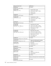
... 3. Hard Disk Drive Cable 2. Check power supply voltages 3. Reseat the hard disk drive cable 4. System board No action 1. System board No action No action 1. System board No action 1. CD-ROM drive 4. System ... action 1. Hard Disk drive (IDE) 5. Hard Disk Drive Cable 2. SCSI adapter card 6. Diskette Drive Cable 2. CD-ROM Drive Cable 2. Hard Disk drive (SCSI) 5. Check power supply voltages 3. Check power supply voltages 3. Check and test Keyboard 3. Diagnostic Error Code 206-000-XXX Diskette Drive Test Passed 206-XXX-XXX Diskette Drive error 215-000-XXX...
... 3. Hard Disk Drive Cable 2. Check power supply voltages 3. Reseat the hard disk drive cable 4. System board No action 1. System board No action No action 1. System board No action 1. CD-ROM drive 4. System ... action 1. Hard Disk drive (IDE) 5. Hard Disk Drive Cable 2. SCSI adapter card 6. Diskette Drive Cable 2. CD-ROM Drive Cable 2. Hard Disk drive (SCSI) 5. Check power supply voltages 3. Check power supply voltages 3. Check and test Keyboard 3. Diagnostic Error Code 206-000-XXX Diskette Drive Test Passed 206-XXX-XXX Diskette Drive error 215-000-XXX...
Hardware Maintenance Manual
Page 85
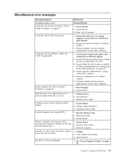
...Dead computer. Network adapter (advise network administrator of new MAC address) Computer will not perform a Wake On LAN® (if applicable) 1. Power Supply 2. System Board 3. Primary Hard Disk Drive 3. Run the Memory tests 2. System Board ″Insert a Diskette″ icon appears with an ... on or does not light when drive is enabled in startup sequence as first device or first device after diskette 2. Check power supply and signal cable connections to -FRU Index 79 Diskette Drive Cable 3. System Board 2. Miscellaneous error messages Message/Symptom FRU/Action...
...Dead computer. Network adapter (advise network administrator of new MAC address) Computer will not perform a Wake On LAN® (if applicable) 1. Power Supply 2. System Board 3. Primary Hard Disk Drive 3. Run the Memory tests 2. System Board ″Insert a Diskette″ icon appears with an ... on or does not light when drive is enabled in startup sequence as first device or first device after diskette 2. Check power supply and signal cable connections to -FRU Index 79 Diskette Drive Cable 3. System Board 2. Miscellaneous error messages Message/Symptom FRU/Action...
Hardware Maintenance Manual
Page 86
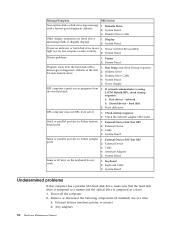
...but computer works correctly 2. Keyboard Cable 3. Display 2. Cable 4. Cable 4. Any adapters 80 Hardware Maintenance Manual port) 2. System Board Power-on indicator or hard disk drive in the first 3.5-inch diskette drive 1. System Board 5. Diskette Drive 3. Hard disk drive RPL ...FRU/Action Non-system disk or disk error-type message with a known-good diagnostics diskette in -use 1. System Board 3. Power Supply RPL computer cannot access programs from server 1. Check the network adapter LED status Serial or parallel port device failure (system board...
...but computer works correctly 2. Keyboard Cable 3. Display 2. Cable 4. Cable 4. Any adapters 80 Hardware Maintenance Manual port) 2. System Board Power-on indicator or hard disk drive in the first 3.5-inch diskette drive 1. System Board 5. Diskette Drive 3. Hard disk drive RPL ...FRU/Action Non-system disk or disk error-type message with a known-good diagnostics diskette in -use 1. System Board 3. Power Supply RPL computer cannot access programs from server 1. Check the network adapter LED status Serial or parallel port device failure (system board...

Hardware Maintenance Manual
Page 91
... connect the cables on the rear of connectors on your computer. Desktop computers 85 Rear connectors This illustration shows the location of your computer. 1 Power cord connector 2 Power-supply-diagnostic LEDs (some models) 3 Audio-line-in connector 4 Audio-line-out connector 5 Microphone 6 Serial connector 7 Parallel connector 8 VGA-monitor connector 9 USB connectors (2) 10 External...
... connect the cables on the rear of connectors on your computer. Desktop computers 85 Rear connectors This illustration shows the location of your computer. 1 Power cord connector 2 Power-supply-diagnostic LEDs (some models) 3 Audio-line-in connector 4 Audio-line-out connector 5 Microphone 6 Serial connector 7 Parallel connector 8 VGA-monitor connector 9 USB connectors (2) 10 External...
Hardware Maintenance Manual
Page 92
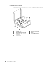
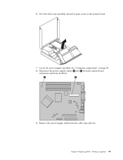
Computer components This illustration shows the location of the various components in your computer. 1 Hard disk drive 2 Microprocessor and heat sink 3 Optical drive (such as a CD or DVD drive) 4 Diskette drive 5 Memory connectors (4) 6 Battery 7 Power-supply assembly 86 Hardware Maintenance Manual
Computer components This illustration shows the location of the various components in your computer. 1 Hard disk drive 2 Microprocessor and heat sink 3 Optical drive (such as a CD or DVD drive) 4 Diskette drive 5 Memory connectors (4) 6 Battery 7 Power-supply assembly 86 Hardware Maintenance Manual
Hardware Maintenance Manual
Page 100
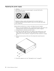
...on page 84 and "Rear connectors" on page 88. 94 Hardware Maintenance Manual Replacing the power supply Attention Never remove the cover on a power supply or any part that secure the power supply. 5. Hazardous voltage, current, and energy levels are present inside any component that are no ...servicable parts inside these components. This includes power cords, input/output (I/O) cables, and any media (diskettes, ...
...on page 84 and "Rear connectors" on page 88. 94 Hardware Maintenance Manual Replacing the power supply Attention Never remove the cover on a power supply or any part that secure the power supply. 5. Hazardous voltage, current, and energy levels are present inside any component that are no ...servicable parts inside these components. This includes power cords, input/output (I/O) cables, and any media (diskettes, ...
Hardware Maintenance Manual
Page 101
Pivot the drive bay assembly upward to gain access to the system board. 7. See "Computer components" on page 86. 8. Chapter 8. Locate the power-supply assembly. Replacing FRUs - 6. Desktop computers 95 Disconnect the power supply cables 1 and 2 from the system-board connectors and from the cable clips and ties. Remove the power-supply cables from all drives. 9.
Pivot the drive bay assembly upward to gain access to the system board. 7. See "Computer components" on page 86. 8. Chapter 8. Locate the power-supply assembly. Replacing FRUs - 6. Desktop computers 95 Disconnect the power supply cables 1 and 2 from the system-board connectors and from the cable clips and ties. Remove the power-supply cables from all drives. 9.
Hardware Maintenance Manual
Page 102
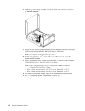
... V. Install the new power-supply assembly into the chassis so that the screw holes in the power-supply assembly align with those in the chassis. v If the voltage supply range is 200-240 V ac, set the switch to 230 V. 14. Note: Use only the screws provided by Lenovo. 12. These computers ...automatically control the voltage. Go to secure the power-supply assembly. 13.
... V. Install the new power-supply assembly into the chassis so that the screw holes in the power-supply assembly align with those in the chassis. v If the voltage supply range is 200-240 V ac, set the switch to 230 V. 14. Note: Use only the screws provided by Lenovo. 12. These computers ...automatically control the voltage. Go to secure the power-supply assembly. 13.
Hardware Maintenance Manual
Page 118
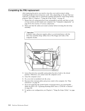
... of the hinges and sides of various components. 2. If you must update (flash) the BIOS. Reconnect the external cables and power cords to avoid interference with the drive bay assembly. Important Correctly route all components have been reassembled correctly and that no tools or...part that the cables are routed correctly before lowering the drive-bay assembly. See "Rear connectors" on page 494. 8. Ensure that all power supply cables to the computer. Close the computer cover. 5. Completing the FRU replacement After replacing the parts, you cannot close the cover and reconnect...
... of the hinges and sides of various components. 2. If you must update (flash) the BIOS. Reconnect the external cables and power cords to avoid interference with the drive bay assembly. Important Correctly route all components have been reassembled correctly and that no tools or...part that the cables are routed correctly before lowering the drive-bay assembly. See "Rear connectors" on page 494. 8. Ensure that all power supply cables to the computer. Close the computer cover. 5. Completing the FRU replacement After replacing the parts, you cannot close the cover and reconnect...

Hardware Maintenance Manual
Page 121
Ultra SFF Desktop computers 115 Replacing FRUs - Rear connectors The following illustration shows the location of connectors on the rear of the computer. 1 PCI adapter connector 2 Integrated cable lock-latch 3 USB connector 4 USB connector 5 VGA monitor connector 6 Parallel connector 7 Serial connector 8 Ethernet connector 9 USB connectors (2) 10 ESATA connector 11 USB connectors (2) 12 Audio-line-out connector 13 Audio-line-in connector 14 Power supply diagnostic LEDs (some models) 15 Power connector Chapter 9.
Ultra SFF Desktop computers 115 Replacing FRUs - Rear connectors The following illustration shows the location of connectors on the rear of the computer. 1 PCI adapter connector 2 Integrated cable lock-latch 3 USB connector 4 USB connector 5 VGA monitor connector 6 Parallel connector 7 Serial connector 8 Ethernet connector 9 USB connectors (2) 10 ESATA connector 11 USB connectors (2) 12 Audio-line-out connector 13 Audio-line-in connector 14 Power supply diagnostic LEDs (some models) 15 Power connector Chapter 9.


