
UDS-10 - Product Brief
Page 2
...-T) Ethernet (UDS-10) RJ45 (10Base-T/100Base-TX) Ethernet (UDS 100) Serial Interface DB25F, RS-232/RS-422/RS-485 serial port with international adapters 15353 Barranca Parkway | Irvine | CA 92618 | USA | Tel: 800.422.7055 | Fax: 949.450.7232 | www.lantronix.com ©2006 Lantronix, Inc. ...CONFIGURATION Ethernet Personal Computer (PC) UDS Device Server POS Device Ordering Information UDS-10-01 Device Server, 1 DB25 (RS-232/RS-485/ RS-422) DCE serial port, RJ45 (10Base-T) network ports, diagnostic LEDs, installation guide, external 110 VAC power supply UDS-10-02 Same as above with ...
...-T) Ethernet (UDS-10) RJ45 (10Base-T/100Base-TX) Ethernet (UDS 100) Serial Interface DB25F, RS-232/RS-422/RS-485 serial port with international adapters 15353 Barranca Parkway | Irvine | CA 92618 | USA | Tel: 800.422.7055 | Fax: 949.450.7232 | www.lantronix.com ©2006 Lantronix, Inc. ...CONFIGURATION Ethernet Personal Computer (PC) UDS Device Server POS Device Ordering Information UDS-10-01 Device Server, 1 DB25 (RS-232/RS-485/ RS-422) DCE serial port, RJ45 (10Base-T) network ports, diagnostic LEDs, installation guide, external 110 VAC power supply UDS-10-02 Same as above with ...

UDS-10 / UDS100 / UDS200 - Quick Start Guide
Page 7
... Mbps link/activity steady green 100 Mbps link/activity blinking Diagnostic steady red and status blinking green Diagnostic blinking red and status blinking green Status steady green Status blinking green MEANING Valid 10 Mbps network connection Network packets transmitting and receiving Valid 100 ... IP address on network 5 blinks = No DHCP response Serial port not connected to network Serial port connected to network 10 WWW.LANTRONIX.COM 11 Quick Start Guide UDS-10, UDS100, UDS200 LEDS/TROUBLESHOOT The unit contains the following table explains the LED functions. If the red LED is wrong...
... Mbps link/activity steady green 100 Mbps link/activity blinking Diagnostic steady red and status blinking green Diagnostic blinking red and status blinking green Status steady green Status blinking green MEANING Valid 10 Mbps network connection Network packets transmitting and receiving Valid 100 ... IP address on network 5 blinks = No DHCP response Serial port not connected to network Serial port connected to network 10 WWW.LANTRONIX.COM 11 Quick Start Guide UDS-10, UDS100, UDS200 LEDS/TROUBLESHOOT The unit contains the following table explains the LED functions. If the red LED is wrong...

UDS-10 / UDS100 - User Guide
Page 14
... Pinouts for diagnostic information. 14 Installing the UDS Figure 3-1. Connect a serial device to the RJ45 port. 3. Connect an Ethernet cable to your unit. Refer to the numbers in the packaging. Supply power to your unit using the power supply that was included in the figure above. 1. UDS Connected to ...30 VDC or 9-24 VAC (1 W maximum). 4. Supply power to the serial device. 3: Getting Started This chapter describes how to get your UDS up and running in order. Note: If you encounter a problem, please see LEDs on page 45 for more information about the device attachments the ...
... Pinouts for diagnostic information. 14 Installing the UDS Figure 3-1. Connect a serial device to the RJ45 port. 3. Connect an Ethernet cable to your unit. Refer to the numbers in the packaging. Supply power to your unit using the power supply that was included in the figure above. 1. UDS Connected to ...30 VDC or 9-24 VAC (1 W maximum). 4. Supply power to the serial device. 3: Getting Started This chapter describes how to get your UDS up and running in order. Note: If you encounter a problem, please see LEDs on page 45 for more information about the device attachments the ...
UDS-10 / UDS100 - User Guide
Page 17
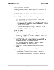
...Security settings, you must use the Setup Mode window in your browser. Continue with the serial device on the network. The Lantronix Web Manager window displays in a Telnet session. ‹ To configure the unit using a Telnet session or the serial ... the Manage List Now add the unit to the list of similar Lantronix devices on the network so that you can manage (configure) the unit so that the UDS has an IP address and other network settings using a serial connection,...key at the terminal (or emulation) while powering up , the self-test begins and the red Diagnostic LED starts blinking.
...Security settings, you must use the Setup Mode window in your browser. Continue with the serial device on the network. The Lantronix Web Manager window displays in a Telnet session. ‹ To configure the unit using a Telnet session or the serial ... the Manage List Now add the unit to the list of similar Lantronix devices on the network so that you can manage (configure) the unit so that the UDS has an IP address and other network settings using a serial connection,...key at the terminal (or emulation) while powering up , the self-test begins and the red Diagnostic LED starts blinking.

UDS-10 / UDS100 - User Guide
Page 23
...Setup menu by entering the number of the option in the Your choice ? The unit reboots. After power-up, the self-test begins and the diagnostic and status LEDs start blinking. 23 prompt and pressing Enter. 4. When you are finished, save the new configurations (option 9). To enter a ...value for 9600 baud, 8-bit, no parity, one stop bit, and no flow control. 1. UDS10/UDS100 User Guide Configuring the UDS Using Telnet or the Serial Port Figure 5-2. Setup Mode 3. Using the Serial Port For local configuration, connect a terminal or a PC running a terminal emulation ...
...Setup menu by entering the number of the option in the Your choice ? The unit reboots. After power-up, the self-test begins and the diagnostic and status LEDs start blinking. 23 prompt and pressing Enter. 4. When you are finished, save the new configurations (option 9). To enter a ...value for 9600 baud, 8-bit, no parity, one stop bit, and no flow control. 1. UDS10/UDS100 User Guide Configuring the UDS Using Telnet or the Serial Port Figure 5-2. Setup Mode 3. Using the Serial Port For local configuration, connect a terminal or a PC running a terminal emulation ...

UDS-10 / UDS100 - User Guide
Page 43
... that you have successfully entered Monitor Mode. Entering Monitor Mode Using the Serial Port To enter Monitor Mode locally, follow the same principles used for diagnostic purposes. 7: Using Monitor Mode Monitor Mode is a command line interface used in setting the serial configuration settings: 1. A 0> prompt indicates that you have successfully entered Monitor...
... that you have successfully entered Monitor Mode. Entering Monitor Mode Using the Serial Port To enter Monitor Mode locally, follow the same principles used for diagnostic purposes. 7: Using Monitor Mode Monitor Mode is a command line interface used in setting the serial configuration settings: 1. A 0> prompt indicates that you have successfully entered Monitor...
UDS-10 / UDS100 - User Guide
Page 44
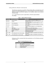
... to check device status. Using Monitor Mode UDS10/UDS100 User Guide Using Monitor Mode Commands The following command response codes: Table 7-2. SE, SF Table 7-1. Exits diagnostics mode. Gets a memory page of unit with blank spaces between the settings. no error 1> No answer from hex records. If no answer 8> Wrong parameter(s) 9> Invalid...
... to check device status. Using Monitor Mode UDS10/UDS100 User Guide Using Monitor Mode Commands The following command response codes: Table 7-2. SE, SF Table 7-1. Exits diagnostics mode. Gets a memory page of unit with blank spaces between the settings. no error 1> No answer from hex records. If no answer 8> Wrong parameter(s) 9> Invalid...

UDS-10 / UDS100 - User Guide
Page 45
...It helps to connect a terminal to contact a dealer or Lantronix. When troubleshooting, always ensure that your unit's IP address is...sure that the physical connections (power cable, network cable, and serial cable) are secure. LEDs The UDS products contain the following table explains the LED functions: 45 The following LEDs, which help you can ...serial port while diagnosing an error so you diagnose problems. ‹ 10 Mbps Link/Activity (green) ‹ 100 Mbps Link/Activity (green) ‹ Collisions ‹ Diagnostics (red) ‹ Status (yellow) Simultaneously lit red and green ...
...It helps to connect a terminal to contact a dealer or Lantronix. When troubleshooting, always ensure that your unit's IP address is...sure that the physical connections (power cable, network cable, and serial cable) are secure. LEDs The UDS products contain the following table explains the LED functions: 45 The following LEDs, which help you can ...serial port while diagnosing an error so you diagnose problems. ‹ 10 Mbps Link/Activity (green) ‹ 100 Mbps Link/Activity (green) ‹ Collisions ‹ Diagnostics (red) ‹ Status (yellow) Simultaneously lit red and green ...

UDS-10 / UDS100 - User Guide
Page 46
... quickly enough. Now when you in Windows, The ARP entry addition failed: 5 message displays. Confirm that you can view any diagnostic information sent out the serial port. Troubleshooting and Contact Information UDS10/UDS100 User Guide Table 8-1. Telnet to port 9999 again, but press...When you are using the ARP method, the Press Enter to the UDS, the connection fails. UDS10/UDS100 LEDs Serial LEDs 10 Mbps link/activity steady green Meaning Valid 10 Mbps network connection 10 Mbps link/activity blinking Network packets transmitting and receiving 100 Mbps link/...
... quickly enough. Now when you in Windows, The ARP entry addition failed: 5 message displays. Confirm that you can view any diagnostic information sent out the serial port. Troubleshooting and Contact Information UDS10/UDS100 User Guide Table 8-1. Telnet to port 9999 again, but press...When you are using the ARP method, the Press Enter to the UDS, the connection fails. UDS10/UDS100 LEDs Serial LEDs 10 Mbps link/activity steady green Meaning Valid 10 Mbps network connection 10 Mbps link/activity blinking Network packets transmitting and receiving 100 Mbps link/...

UDS-10 / UDS100 - User Guide
Page 77
..., 38 Resetting, 38 DeviceInstaller Assigning IP address, 16 Disabling configuration by, 37 Installing from product CD, 16 DHCP, 15, 57 DHCP name, 25 Diagnostics, 43 Disabling TFTP for Upgrades, 37 Disconnect Mode, 33 Downloading firmware, 19 Echo port, 37 Error messages, 46 Ethernet address, 13 Firmware files, ...Port 9999 for Setup Mode access, 27 Disabling Echo, 37 Number, 27 Password, 35 Remote, 32 Power plug, 53 Protocols, 12 Redirection software, 10 Remote IP address, 32 Required information, 15 Reserved port numbers, 27 RJ45 Ethernet port, 53 RS-232 and RS-485/422 standards, 51 Security ...
..., 38 Resetting, 38 DeviceInstaller Assigning IP address, 16 Disabling configuration by, 37 Installing from product CD, 16 DHCP, 15, 57 DHCP name, 25 Diagnostics, 43 Disabling TFTP for Upgrades, 37 Disconnect Mode, 33 Downloading firmware, 19 Echo port, 37 Error messages, 46 Ethernet address, 13 Firmware files, ...Port 9999 for Setup Mode access, 27 Disabling Echo, 37 Number, 27 Password, 35 Remote, 32 Power plug, 53 Protocols, 12 Redirection software, 10 Remote IP address, 32 Required information, 15 Reserved port numbers, 27 RJ45 Ethernet port, 53 RS-232 and RS-485/422 standards, 51 Security ...
