
UDS-10 / UDS100 / UDS200 - Quick Start Guide
Page 2
UDS-10, UDS100, UDS200 UDS-10, UDS100, UDS200 QUICK START CONTENTS What's In the Box 2 Pinouts 3 IP Addressing 4 Connect 5 Install the Deviceinstaller GUI 6 Assign IP Address 6-8 Configure the UDS-10, UDS100, UDS200 9 Troubleshoot 10 Contact 12
UDS-10, UDS100, UDS200 UDS-10, UDS100, UDS200 QUICK START CONTENTS What's In the Box 2 Pinouts 3 IP Addressing 4 Connect 5 Install the Deviceinstaller GUI 6 Assign IP Address 6-8 Configure the UDS-10, UDS100, UDS200 9 Troubleshoot 10 Contact 12
UDS-10 / UDS100 / UDS200 - Quick Start Guide
Page 3
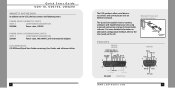
For more detailed information or alternative configuration methods, refer to the UDS, the box contains the following items: POWER SUPPLY (DOMESTIC UNITS) PART # COMPONENT DESCRIPTION 520-006 Power cube, 110 VAC POWER SUPPLY (INTERNATIONAL UNITS)..., UDS200 WHAT'S IN THE BOX In addition to the User Guide on the CD. Ethernet, Power, and Serial Connections PINOUTS UDS-10 UDS100 UDS200 2 WWW.LANTRONIX.COM 3 The UDS products allow serial devices to connect, configure, and troubleshoot your unit using a network connection and our DeviceInstaller software. This Quick Start explains...
For more detailed information or alternative configuration methods, refer to the UDS, the box contains the following items: POWER SUPPLY (DOMESTIC UNITS) PART # COMPONENT DESCRIPTION 520-006 Power cube, 110 VAC POWER SUPPLY (INTERNATIONAL UNITS)..., UDS200 WHAT'S IN THE BOX In addition to the User Guide on the CD. Ethernet, Power, and Serial Connections PINOUTS UDS-10 UDS100 UDS200 2 WWW.LANTRONIX.COM 3 The UDS products allow serial devices to connect, configure, and troubleshoot your unit using a network connection and our DeviceInstaller software. This Quick Start explains...

UDS-10 / UDS100 - User Guide
Page 5
... the Network 43 Using Monitor Mode Commands 44 8: Troubleshooting and Contact Information 45 LEDs 45 Problems and Error Messages 46 Technical Support 49 9: Connections and Pinouts 51 Serial Port 51 Serial Connector Pinouts 51 Null-Modem Cable 53 5
... the Network 43 Using Monitor Mode Commands 44 8: Troubleshooting and Contact Information 45 LEDs 45 Problems and Error Messages 46 Technical Support 49 9: Connections and Pinouts 51 Serial Port 51 Serial Connector Pinouts 51 Null-Modem Cable 53 5

UDS-10 / UDS100 - User Guide
Page 6
... 43 Figure 9-1. Sample Ethernet Address 13 Figure 3-1. Web Browser Login 18 Figure 4-2. UDS Configuration Guidelines Page 19 Figure 4-3. Expert Settings Options 35 Figure 5-8. DB25 Female DCE ... 4-1. DB25 Female DCE Interface RS485/422 52 6 Setup Mode 23 Figure 5-3. Lantronix Web Manager 20 Figure 4-4. Network Configuration 24 Figure 5-4. Server Properties Configuration on ...42 Figure 7-1. UDS10/UDS100 User Guide Network Port 53 Ethernet Connector Pinouts 54 10: Technical Specifications 55 UDS10 Technical Specifications 55 UDS100 Technical Specifications 56 A:...
... 43 Figure 9-1. Sample Ethernet Address 13 Figure 3-1. Web Browser Login 18 Figure 4-2. UDS Configuration Guidelines Page 19 Figure 4-3. Expert Settings Options 35 Figure 5-8. DB25 Female DCE ... 4-1. DB25 Female DCE Interface RS485/422 52 6 Setup Mode 23 Figure 5-3. Lantronix Web Manager 20 Figure 4-4. Network Configuration 24 Figure 5-4. Server Properties Configuration on ...42 Figure 7-1. UDS10/UDS100 User Guide Network Port 53 Ethernet Connector Pinouts 54 10: Technical Specifications 55 UDS10 Technical Specifications 55 UDS100 Technical Specifications 56 A:...

UDS-10 / UDS100 - User Guide
Page 8
...listing all UDS configuration options in this guide include: 2: Introduction 3: Getting Started 4: Configuring the UDS Using Web Manager 5: Configuring the UDS Using Telnet or the Serial Port 6: Updating Firmware 7: Using Monitor Mode 8: Troubleshooting and Contact Information 9: Connections and Pinouts 10: Technical ... for installing your unit and getting it to contact Lantronix Technical Support. It is for system administrators and those responsible for the UDS. Provides descriptions and illustrations of the UDS and the protocols it supports. Provides detailed information about...
...listing all UDS configuration options in this guide include: 2: Introduction 3: Getting Started 4: Configuring the UDS Using Web Manager 5: Configuring the UDS Using Telnet or the Serial Port 6: Updating Firmware 7: Using Monitor Mode 8: Troubleshooting and Contact Information 9: Connections and Pinouts 10: Technical ... for installing your unit and getting it to contact Lantronix Technical Support. It is for system administrators and those responsible for the UDS. Provides descriptions and illustrations of the UDS and the protocols it supports. Provides detailed information about...

UDS-10 / UDS100 - User Guide
Page 14
... a problem, please see LEDs on page 45 for more information about the device attachments the unit supports. 2. Installing the UDS Figure 3-1. See 9: Connections and Pinouts for diagnostic information. 14 Supply power to your UDS up and running in the shortest possible time. Supply power to the RJ45 port. 3. Connect an Ethernet cable to...
... a problem, please see LEDs on page 45 for more information about the device attachments the unit supports. 2. Installing the UDS Figure 3-1. See 9: Connections and Pinouts for diagnostic information. 14 Supply power to your UDS up and running in the shortest possible time. Supply power to the RJ45 port. 3. Connect an Ethernet cable to...

UDS-10 / UDS100 - User Guide
Page 19
UDS10/UDS100 User Guide Configuring the UDS Using Web Manager Figure 4-2. UDS Configuration Guidelines Page ‹ UDS settings opens a configuration window to configure the UDS10/UDS100, as shown in Figure 4-3. ‹ Serial cabling lets you view pinouts for the UDS serial port. ‹ View UDS Configuration Tutorials provides step-by-step instructions for configuring serial tunneling and the Com Port Redirector. ‹ Technical Support lets you download the latest firmware for your UDS and view documentation. 19
UDS10/UDS100 User Guide Configuring the UDS Using Web Manager Figure 4-2. UDS Configuration Guidelines Page ‹ UDS settings opens a configuration window to configure the UDS10/UDS100, as shown in Figure 4-3. ‹ Serial cabling lets you view pinouts for the UDS serial port. ‹ View UDS Configuration Tutorials provides step-by-step instructions for configuring serial tunneling and the Com Port Redirector. ‹ Technical Support lets you download the latest firmware for your UDS and view documentation. 19

UDS-10 / UDS100 - User Guide
Page 51
9: Connections and Pinouts Serial Port The UDS has a female DCE DB25 serial port that supports RS-232 and RS-485/422 serial standards (software selectable) up to 115 Kbps. Figure 9-1. The default serial port settings are 9600 baud, 8 bits, no parity, and 1 stop bit. 51 Serial Interface Serial Connector Pinouts The unit's female DB25 connector provides an RS-232C, RS-485, or RS-422 DCE serial port.
9: Connections and Pinouts Serial Port The UDS has a female DCE DB25 serial port that supports RS-232 and RS-485/422 serial standards (software selectable) up to 115 Kbps. Figure 9-1. The default serial port settings are 9600 baud, 8 bits, no parity, and 1 stop bit. 51 Serial Interface Serial Connector Pinouts The unit's female DB25 connector provides an RS-232C, RS-485, or RS-422 DCE serial port.

UDS-10 / UDS100 - User Guide
Page 52
DB25 Female DCE Interface RS485/422 52 DB25 Female DCE Interface RS232 Figure 9-3. Connections and Pinouts UDS10/UDS100 User Guide Figure 9-2.
DB25 Female DCE Interface RS485/422 52 DB25 Female DCE Interface RS232 Figure 9-3. Connections and Pinouts UDS10/UDS100 User Guide Figure 9-2.
UDS-10 / UDS100 - User Guide
Page 53
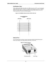
...To configure the UDS using the DB9 serial port, you only need to DB9 null-modem cable. Null-Modem Cable (Lantronix Part No. 500-163) Network Port The unit's back panel contains a power plug and an RJ45 (10/100) Ethernet port. The figure below shows the pinouts for a DB9 to pinout the TXD,... RXD, and GND signals. Power input range on a PC, use a null-modem cable (Lantronix Part No. 500-163). UDS10/UDS100 User Guide Connectons and...
...To configure the UDS using the DB9 serial port, you only need to DB9 null-modem cable. Null-Modem Cable (Lantronix Part No. 500-163) Network Port The unit's back panel contains a power plug and an RJ45 (10/100) Ethernet port. The figure below shows the pinouts for a DB9 to pinout the TXD,... RXD, and GND signals. Power input range on a PC, use a null-modem cable (Lantronix Part No. 500-163). UDS10/UDS100 User Guide Connectons and...

UDS-10 / UDS100 - User Guide
Page 54
The UDS100 supports 100 Mbps half or full duplex Ethernet through an RJ45 connector. Figure 9-6. RJ45 Ethernet Connector 54 Connections and Pinouts UDS10/UDS100 User Guide Ethernet Connector Pinouts The UDS10 supports 10 Mbps half-duplex Ethernet through an RJ45 connector.
The UDS100 supports 100 Mbps half or full duplex Ethernet through an RJ45 connector. Figure 9-6. RJ45 Ethernet Connector 54 Connections and Pinouts UDS10/UDS100 User Guide Ethernet Connector Pinouts The UDS10 supports 10 Mbps half-duplex Ethernet through an RJ45 connector.

UDS-10 / UDS100 - User Guide
Page 55
... Technical Specifications CPU, Memory x86 CPU, 25MHz clock, 128kByte RAM Serial Interface Female DB25 connector (DCE pinout) Speed software selectable (300 to 115 kBaud) Software selectable RS-232C or RS-422/485 Network Interface 10 Mbps RJ45 Ethernet Power Supply External adapter included 120 VAC USA 100 - 240 VAC Universal with regional... range: 5° to 50° C (41° to 122° F) Storage range: -40° to 66° C (-40° to 151° F) Relative Humidity Operating: 10% to 90% non-condensing, 40% to 60% recommended Storage...
... Technical Specifications CPU, Memory x86 CPU, 25MHz clock, 128kByte RAM Serial Interface Female DB25 connector (DCE pinout) Speed software selectable (300 to 115 kBaud) Software selectable RS-232C or RS-422/485 Network Interface 10 Mbps RJ45 Ethernet Power Supply External adapter included 120 VAC USA 100 - 240 VAC Universal with regional... range: 5° to 50° C (41° to 122° F) Storage range: -40° to 66° C (-40° to 151° F) Relative Humidity Operating: 10% to 90% non-condensing, 40% to 60% recommended Storage...

UDS-10 / UDS100 - User Guide
Page 56
... Guide UDS100 Technical Specifications CPU, Memory Lantronix DSTni-LX 186 CPU, 48 MHz 1 MByte FLASH ROM 256 Kbytes zero wait state RAM Serial Interface Female DB25 connector (DCE pinout) Speed software selectable (300 to 115 kBaud) Software selectable RS-232C or RS-422/485 Network Interface 10/100 RJ45 Ethernet Power Supply External... range: 5° to 50° C (41° to 122° F) Storage range: -40° to 66° C (-40° to 151° F) Relative Humidity Operating: 10% to 90% non-condensing, 40% to 60% recommended Storage...
... Guide UDS100 Technical Specifications CPU, Memory Lantronix DSTni-LX 186 CPU, 48 MHz 1 MByte FLASH ROM 256 Kbytes zero wait state RAM Serial Interface Female DB25 connector (DCE pinout) Speed software selectable (300 to 115 kBaud) Software selectable RS-232C or RS-422/485 Network Interface 10/100 RJ45 Ethernet Power Supply External... range: 5° to 50° C (41° to 122° F) Storage range: -40° to 66° C (-40° to 151° F) Relative Humidity Operating: 10% to 90% non-condensing, 40% to 60% recommended Storage...

UDS-10 / UDS100 - User Guide
Page 77
...Mode, 30 Monitor Mode Accessing, 43 Commands, 44 Network class, 16 Null-modem cable, 53 Pack control, 34 Password Channel (Port), 35 Enhanced security, 37 Pinouts, 19, 51 Port 9999 for Setup Mode access, 27 Disabling Echo, 37 Number, 27 Password, 35 Remote, 32 Power plug, 53 Protocols, 12 Redirection ...software, 10 Remote IP address, 32 Required information, 15 Reserved port numbers, 27 RJ45 Ethernet port, 53 RS-232 and RS-485/422 standards, 51 Security settings,...
...Mode, 30 Monitor Mode Accessing, 43 Commands, 44 Network class, 16 Null-modem cable, 53 Pack control, 34 Password Channel (Port), 35 Enhanced security, 37 Pinouts, 19, 51 Port 9999 for Setup Mode access, 27 Disabling Echo, 37 Number, 27 Password, 35 Remote, 32 Power plug, 53 Protocols, 12 Redirection ...software, 10 Remote IP address, 32 Required information, 15 Reserved port numbers, 27 RJ45 Ethernet port, 53 RS-232 and RS-485/422 standards, 51 Security settings,...