
MatchPort b/g - Integration Guide
Page 3
...met, further transmitter testing will void the user's authority to operate with this device not explicitly approved by Lantronix will not be required. Integration Note a) This module is maintained between the antenna and users. So, the... valid and the FCC ID cannot be met (for use with the antennas listed in this device. MatchPort b/g Integration Guide 3 Updated absolute maximum ratings and recommended supply voltage information. However, the OEM integrator is...jumper configuration, recommended operating conditions, technical specifications and the PCB interface signal.
...met, further transmitter testing will void the user's authority to operate with this device not explicitly approved by Lantronix will not be required. Integration Note a) This module is maintained between the antenna and users. So, the... valid and the FCC ID cannot be met (for use with the antennas listed in this device. MatchPort b/g Integration Guide 3 Updated absolute maximum ratings and recommended supply voltage information. However, the OEM integrator is...jumper configuration, recommended operating conditions, technical specifications and the PCB interface signal.

MatchPort b/g - Integration Guide
Page 4
... Figures 5 List of Tables 5 1: Introduction 6 About the Integration Guide 6 Additional Documentation 6 2: Description and Specifications 7 MatchPort b/g Overview 7 MatchPort b/g Block Diagram 8 PCB Interface 9 Mating Connector 9 Serial Input/Output 10 Sample Layouts for RS-485 Connectivity 11 WLAN Input/Output 12 MatchPort b/g 12 Power, Ground, and Reset 13 Absolute Maximum Ratings 13 Recommended Operating Conditions 13 Wireless...
... Figures 5 List of Tables 5 1: Introduction 6 About the Integration Guide 6 Additional Documentation 6 2: Description and Specifications 7 MatchPort b/g Overview 7 MatchPort b/g Block Diagram 8 PCB Interface 9 Mating Connector 9 Serial Input/Output 10 Sample Layouts for RS-485 Connectivity 11 WLAN Input/Output 12 MatchPort b/g 12 Power, Ground, and Reset 13 Absolute Maximum Ratings 13 Recommended Operating Conditions 13 Wireless...

MatchPort b/g - Integration Guide
Page 5
Combined RS-232/422 Transceiver 11 Figure 2-5. MatchPort b/g Demo Board Layout 23 Figure 3-2. PCB Interface Signals 9 Table 2-2. Demo Board JP5 Jumper Configuration 22 Table 3-7. Bottom View 17 Figure 2-10. PCB Layout (Top View 18 Figure 2-12. Product Label 19 Figure 3-1. RS232 Connections 10 Table 2-3. Power, Ground, and Reset Pins 13 Table 2-6. RS-232 Signals...
Combined RS-232/422 Transceiver 11 Figure 2-5. MatchPort b/g Demo Board Layout 23 Figure 3-2. PCB Interface Signals 9 Table 2-2. Demo Board JP5 Jumper Configuration 22 Table 3-7. Bottom View 17 Figure 2-10. PCB Layout (Top View 18 Figure 2-12. Product Label 19 Figure 3-1. RS232 Connections 10 Table 2-3. Power, Ground, and Reset Pins 13 Table 2-6. RS-232 Signals...
MatchPort b/g - Integration Guide
Page 9
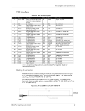
...2 mm 20-pin sockets spaced 1.42" apart can be used (e.g., Samtec P/N SMM-120-02-S-S-TR). Lantronix offers two cable options, reverse-SMA to U.FL (P/N 500-180-R) or U.FL to U.FL (P/N 500-180-R) MatchPort b/g Integration Guide 9 No Connect Transmit data output (logic level), port 0 Request to Send output (logic...data output (logic level), port 1 Request to Send output (logic level), port 1 Receive data input (logic level), port 1 Clear to the PCB using the footprint shown in Figure 2-10. Min reset input 2 ms. Leave floating if unused. Ethernet TX center tap Ethernet RX center tap ...
...2 mm 20-pin sockets spaced 1.42" apart can be used (e.g., Samtec P/N SMM-120-02-S-S-TR). Lantronix offers two cable options, reverse-SMA to U.FL (P/N 500-180-R) or U.FL to U.FL (P/N 500-180-R) MatchPort b/g Integration Guide 9 No Connect Transmit data output (logic level), port 0 Request to Send output (logic...data output (logic level), port 1 Request to Send output (logic level), port 1 Receive data input (logic level), port 1 Clear to the PCB using the footprint shown in Figure 2-10. Min reset input 2 ms. Leave floating if unused. Ethernet TX center tap Ethernet RX center tap ...
MatchPort b/g - Integration Guide
Page 18
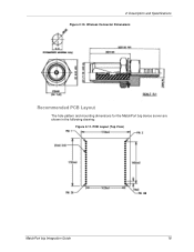
2: Description and Specifications Figure 2-10. PCB Layout (Top View) MatchPort b/g Integration Guide 18 Wireless Connector Dimensions Recommended PCB Layout The hole pattern and mounting dimensions for the MatchPort b/g device server are shown in the following drawing: Figure 2-11.
2: Description and Specifications Figure 2-10. PCB Layout (Top View) MatchPort b/g Integration Guide 18 Wireless Connector Dimensions Recommended PCB Layout The hole pattern and mounting dimensions for the MatchPort b/g device server are shown in the following drawing: Figure 2-11.