

Owner's Manual
Page 1
As an ENERGY STAR Partner LGE U. A.,Inc. S. has determined that this product meets the ENERGY STAR guidelines for energy efficiency. © Copyright 2008, LG Electronics USA, Inc. © Copyright 2008, LG Electronics Canada, Inc. Installation and Operating Guide Model Numbers | Z32LC6D, Z37LC6D, Z32LCD4, Z37LCD4 | LCD TV ENERGY STAR is a set of power-saving guidelines issued by the U.S. Environmental Protection Agency(EPA).
As an ENERGY STAR Partner LGE U. A.,Inc. S. has determined that this product meets the ENERGY STAR guidelines for energy efficiency. © Copyright 2008, LG Electronics USA, Inc. © Copyright 2008, LG Electronics Canada, Inc. Installation and Operating Guide Model Numbers | Z32LC6D, Z37LC6D, Z32LCD4, Z37LCD4 | LCD TV ENERGY STAR is a set of power-saving guidelines issued by the U.S. Environmental Protection Agency(EPA).
Owner's Manual
Page 3
...the equipment and receiver. - Any changes or modifications not expressly approved by turning the equipment off and on a circuit different from LG Electronics. The lightning flash with the instructions, may be connected to the grounding system of the building, as close to Article ...modification could void the user's authority to rain or moisture. NO USER SERVICEABLE PARTS INSIDE. Consult the dealer or an experienced radio/TV technician for compliance could void the user's authority to operate this product to operate the equipment. REFER TO QUALIFIED SERVICE PERSONNEL. However...
...the equipment and receiver. - Any changes or modifications not expressly approved by turning the equipment off and on a circuit different from LG Electronics. The lightning flash with the instructions, may be connected to the grounding system of the building, as close to Article ...modification could void the user's authority to rain or moisture. NO USER SERVICEABLE PARTS INSIDE. Consult the dealer or an experienced radio/TV technician for compliance could void the user's authority to operate this product to operate the equipment. REFER TO QUALIFIED SERVICE PERSONNEL. However...
Owner's Manual
Page 4
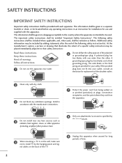
...the other apparatus (including amplifiers)that produce heat. 8 Only use attachments/accessories specified by the manufacturer. 5 When mounting a TV it on the back of the TV. 2 9 Unplug this apparatus near any operating instructions in a separate booklet or sheet, or be located before any heat... safety instructions shall be included where applicable, and, when used . The important safety instructions shall be placed immediately adjacent to install TV by adding statements after the end of the polarized or grounding-type plug. A grounding type plug has two blades and a third...
...the other apparatus (including amplifiers)that produce heat. 8 Only use attachments/accessories specified by the manufacturer. 5 When mounting a TV it on the back of the TV. 2 9 Unplug this apparatus near any operating instructions in a separate booklet or sheet, or be located before any heat... safety instructions shall be included where applicable, and, when used . The important safety instructions shall be placed immediately adjacent to install TV by adding statements after the end of the polarized or grounding-type plug. A grounding type plug has two blades and a third...
Owner's Manual
Page 6
...Sound Settings (Sound Mode) 50 Sound Setting Adjustment - Picture Mode - User Mode 43 - User Mode 51 Balance 52 TV Speakers On/Off Setup 53 Stereo/SAP Broadcasts Setup 54 Audio Language 55 On-Screen Menus Language Selection 56 Caption Mode 57...Cinema 3:2 Pulldown Mode 46 Advanced - Digital Broadcasting System Captions 59 - CONTENTS WARNING / CAUTION 1 SAFETY INSTRUCTIONS 2 FEATURE OF THIS TV 6 PREPARATION Accessories 7 Front Panel Information 8 Back Panel Information 9 Stand Installation 10 VESA Wall Mounting 11 Desktop Pedestal Installation 11 Cable Management 12 ...
...Sound Settings (Sound Mode) 50 Sound Setting Adjustment - Picture Mode - User Mode 43 - User Mode 51 Balance 52 TV Speakers On/Off Setup 53 Stereo/SAP Broadcasts Setup 54 Audio Language 55 On-Screen Menus Language Selection 56 Caption Mode 57...Cinema 3:2 Pulldown Mode 46 Advanced - Digital Broadcasting System Captions 59 - CONTENTS WARNING / CAUTION 1 SAFETY INSTRUCTIONS 2 FEATURE OF THIS TV 6 PREPARATION Accessories 7 Front Panel Information 8 Back Panel Information 9 Stand Installation 10 VESA Wall Mounting 11 Desktop Pedestal Installation 11 Cable Management 12 ...
Owner's Manual
Page 7
Auto Clock Setup 61 Manual Clock Setup 62 Auto On/Off Timer Setting 63 Sleep Timer Setting 64 Auto Shut-off Setting 65 PARENTAL CONTROL / RATINGS Set Password & Lock System 66 Channel Blocking 68 External Input Blocking 68 Movie & TV Rating 69 APPENDIX Troubleshooting 72 Maintenance 74 Product Specifications 75 Programming the Remote Control 76 IR Codes 79 External Control Through RS-232C 81 Open Source License 88 5 TIME SETTING Clock Setting -
Auto Clock Setup 61 Manual Clock Setup 62 Auto On/Off Timer Setting 63 Sleep Timer Setting 64 Auto Shut-off Setting 65 PARENTAL CONTROL / RATINGS Set Password & Lock System 66 Channel Blocking 68 External Input Blocking 68 Movie & TV Rating 69 APPENDIX Troubleshooting 72 Maintenance 74 Product Specifications 75 Programming the Remote Control 76 IR Codes 79 External Control Through RS-232C 81 Open Source License 88 5 TIME SETTING Clock Setting -

Owner's Manual
Page 8
...-definition television. This is normal, there is incorporated under license from SRS Labs, Inc. I If the TV feels cold to the regulations of this product must be visible on the screen. On Disposal The fluorescent lamp used in accordance to... Do not dispose of your finger(s) against it is a trademark of time. However, they have no adverse effect on . Disposal of this product with TV. I Avoid touching the LCD screen or holding your local authority. 6 I Some minute dot defects may produce some temporary distortion effects on the screen, ...
...-definition television. This is normal, there is incorporated under license from SRS Labs, Inc. I If the TV feels cold to the regulations of this product must be visible on the screen. On Disposal The fluorescent lamp used in accordance to... Do not dispose of your finger(s) against it is a trademark of time. However, they have no adverse effect on . Disposal of this product with TV. I Avoid touching the LCD screen or holding your local authority. 6 I Some minute dot defects may produce some temporary distortion effects on the screen, ...
Owner's Manual
Page 9
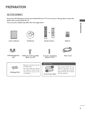
... P CH A G E 123 456 789 0 FLASHBK ADJUST RATIO PICTURE SOUND SAP CC or POWER TV INPUT BRIGHT - If an accessory is missing, please contact the dealer where you purchased the TV. Option Extras D-sub 15 pin Cable When using the VGA (D-sub 15 pin cable) PC connection,... the user must use shielded signal interface cables with ferrite cores to P.13) Power Cord Polishing Cloth * Wipe spots on the exterior only with your TV. The accessories included may cause scratch or discoloration. PICTURE SOUND BRIGHT + 1 2 3 4 56 789 - 0 BACK FAV VOL MUTE CH SAP RETURN...
... P CH A G E 123 456 789 0 FLASHBK ADJUST RATIO PICTURE SOUND SAP CC or POWER TV INPUT BRIGHT - If an accessory is missing, please contact the dealer where you purchased the TV. Option Extras D-sub 15 pin Cable When using the VGA (D-sub 15 pin cable) PC connection,... the user must use shielded signal interface cables with ferrite cores to P.13) Power Cord Polishing Cloth * Wipe spots on the exterior only with your TV. The accessories included may cause scratch or discoloration. PICTURE SOUND BRIGHT + 1 2 3 4 56 789 - 0 BACK FAV VOL MUTE CH SAP RETURN...
Owner's Manual
Page 10
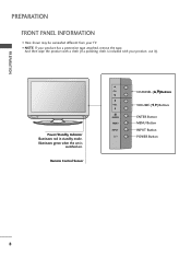
Power/Standby Indicator Illuminates red in standby mode. And then wipe the product with a cloth (If a polishing cloth is switched on. Illuminates green when the set is included with your product has a protection tape attached, remove the tape. Remote Control Sensor CH CH VOL VOL ENTER MENU INEPNUTTER MENU INPUT CHANNEL (D,E)Buttons VOLUME (F,G)Buttons ENTER Button MENU Button INPUT Button POWER Button 8 I Here shown may be somewhat different from your TV. PREPARATION PREPARATION FRONT PANEL INFORMATION I NOTE: If your product, use it).
Power/Standby Indicator Illuminates red in standby mode. And then wipe the product with a cloth (If a polishing cloth is switched on. Illuminates green when the set is included with your product has a protection tape attached, remove the tape. Remote Control Sensor CH CH VOL VOL ENTER MENU INEPNUTTER MENU INPUT CHANNEL (D,E)Buttons VOLUME (F,G)Buttons ENTER Button MENU Button INPUT Button POWER Button 8 I Here shown may be somewhat different from your TV. PREPARATION PREPARATION FRONT PANEL INFORMATION I NOTE: If your product, use it).
Owner's Manual
Page 11
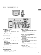
... AUDIO OUT CONTROL IN OPTICAL 6 7 COMPONENT IN 2 2 1 1 HDMI/DVI IN VIDEO AUDIO 2 1 HDMI/DVI IN, HDMI IN Digital Connection. Caution: Never attempt to operate the TV on DC power. 6 ANTENNA/CABLE IN Connect over-the air signals to this jack. Connect cable signals to this jack. 9 Supports HD video and Digital... a wired remote control. Supports HD. S-VIDEO Better quality than standard composition. VIDEO L/MONO AUDIO R R BACK PANEL INFORMATION I Here shown may be somewhat different from your TV.
... AUDIO OUT CONTROL IN OPTICAL 6 7 COMPONENT IN 2 2 1 1 HDMI/DVI IN VIDEO AUDIO 2 1 HDMI/DVI IN, HDMI IN Digital Connection. Caution: Never attempt to operate the TV on DC power. 6 ANTENNA/CABLE IN Connect over-the air signals to this jack. Connect cable signals to this jack. 9 Supports HD video and Digital... a wired remote control. Supports HD. S-VIDEO Better quality than standard composition. VIDEO L/MONO AUDIO R R BACK PANEL INFORMATION I Here shown may be somewhat different from your TV.

Owner's Manual
Page 12
PREPARATION PREPARATION STAND INSTALLATION I Here shown may be somewhat different from your TV. 1 Carefully place the product screen side down on a cushioned surface that will protect product and screen from damage. 2 Assemble the product stand with the product as shown. 3 Securely install the 4 bolts provided. 10
PREPARATION PREPARATION STAND INSTALLATION I Here shown may be somewhat different from your TV. 1 Carefully place the product screen side down on a cushioned surface that will protect product and screen from damage. 2 Assemble the product stand with the product as shown. 3 Securely install the 4 bolts provided. 10
Owner's Manual
Page 13
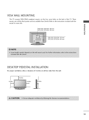
... ventilation by third parties and not available from Zenith. PREPARATION VESA WALL MOUNTING This TV accepts VESA FDMI compliant mounts via the four screw holes on the wall mount used. Z32LC6D, Z32LCD4: 200 mm Z37LC6D, Z37LCD4: 600 mm Z32LC6D, Z32LCD4: 100 mm Z37LC6D, Z37LCD4: 400 mm ! For further information, refer to the instructions...
... ventilation by third parties and not available from Zenith. PREPARATION VESA WALL MOUNTING This TV accepts VESA FDMI compliant mounts via the four screw holes on the wall mount used. Z32LC6D, Z32LCD4: 200 mm Z37LC6D, Z37LCD4: 600 mm Z32LC6D, Z32LCD4: 100 mm Z37LC6D, Z37LCD4: 400 mm ! For further information, refer to the instructions...

Owner's Manual
Page 14
If the product is dropped, you may be injured or the product may be broken. How to remove the CABLE MANAGEMENT CLIP G Hold the CABLE MANAGEMENT CLIP with both hands and pull it backward. 12 NOTE G Do not hold the CABLE MANAGEMENT CLIP when moving the product. - CABLE MANAGEMENT CLIP ! To connect an additional equipment, see the EXTERNAL EQUIPMENT SETUP section. 2 Install the CABLE MANAGEMENT CLIP as necessary. PREPARATION PREPARATION CABLE MANAGEMENT I Here shown may be somewhat different from your TV. 1 Connect the cables as shown.
If the product is dropped, you may be injured or the product may be broken. How to remove the CABLE MANAGEMENT CLIP G Hold the CABLE MANAGEMENT CLIP with both hands and pull it backward. 12 NOTE G Do not hold the CABLE MANAGEMENT CLIP when moving the product. - CABLE MANAGEMENT CLIP ! To connect an additional equipment, see the EXTERNAL EQUIPMENT SETUP section. 2 Install the CABLE MANAGEMENT CLIP as necessary. PREPARATION PREPARATION CABLE MANAGEMENT I Here shown may be somewhat different from your TV. 1 Connect the cables as shown.

Owner's Manual
Page 15
Tipping, shaking, or rocking the machine may cause injury. 13 PREPARATION ATTACHING THE TV TO A DESK The TV must be attached to a desk so it cannot be pulled in a forward/backward direction, potentially causing injury or damaging the product. 1-Screw (provided as parts of the product) Stand Desk WARNING G To prevent TV from falling over, the TV should be securely attached to the floor/wall per installation instructions.
Tipping, shaking, or rocking the machine may cause injury. 13 PREPARATION ATTACHING THE TV TO A DESK The TV must be attached to a desk so it cannot be pulled in a forward/backward direction, potentially causing injury or damaging the product. 1-Screw (provided as parts of the product) Stand Desk WARNING G To prevent TV from falling over, the TV should be securely attached to the floor/wall per installation instructions.

Owner's Manual
Page 16
...a sturdy rope (not provided as shown in a forward direction, potentially causing injury or damaging the product. I Insert the eye-bolts (or TV brackets and bolts) to tighten the product to the holes in the product. I You should purchase necessary components to tie the product. Match... the height of the product, must purchase separately) to prevent TV from the TV. Additionally, we recommend that is safer to a wall so it cannot fall over if pushed backwards. Secure the wall brackets with...
...a sturdy rope (not provided as shown in a forward direction, potentially causing injury or damaging the product. I Insert the eye-bolts (or TV brackets and bolts) to tighten the product to the holes in the product. I You should purchase necessary components to tie the product. Match... the height of the product, must purchase separately) to prevent TV from the TV. Additionally, we recommend that is safer to a wall so it cannot fall over if pushed backwards. Secure the wall brackets with...

Owner's Manual
Page 17
... connect to bend the copper wire when connecting the antenna. ( ) 2. For optimum picture quality, adjust antenna direction if needed. Cable Cable TV Wall Jack RF Coaxial Wire (75 ohm) ANTENNA/ CABLE IN I If the antenna needs to be split for assistance. 15 Antenna (Analog or... Digital) Wall Antenna Socket or Outdoor Antenna without a Cable Box Connections. I If the antenna is not installed properly, contact your dealer for two TV's, install a 2-Way Signal Splitter. I To improve the picture quality in a poor signal area, please purchase a signal amplifi(er )and install properly...
... connect to bend the copper wire when connecting the antenna. ( ) 2. For optimum picture quality, adjust antenna direction if needed. Cable Cable TV Wall Jack RF Coaxial Wire (75 ohm) ANTENNA/ CABLE IN I If the antenna needs to be split for assistance. 15 Antenna (Analog or... Digital) Wall Antenna Socket or Outdoor Antenna without a Cable Box Connections. I If the antenna is not installed properly, contact your dealer for two TV's, install a 2-Way Signal Splitter. I To improve the picture quality in a poor signal area, please purchase a signal amplifi(er )and install properly...
Owner's Manual
Page 18
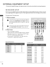
... (Y = green, PB = blue, and PR = red). How to use I Turn on the digital set top box to 1 the COMPONENT IN AUDIO 1 jacks on the TV. 1 2 Supported Resolutions Signal 480i 480p 720p 1080i 1080p Component 1/2 Yes Yes Yes Yes Yes HDMI1/2 No Yes Yes Yes Yes 16 Y PB PR L R Y, CB/PB... Connect the audio output of the digital set -top box. (Refer to COMPONENT IN2 input, select the Component 2 input source on the TV. I Select the Component 1 input source on the TV using the INPUT button on MI IN the set -top box. How to connect 1 Connect the video outputs (Y, PB, PR) of...
... (Y = green, PB = blue, and PR = red). How to use I Turn on the digital set top box to 1 the COMPONENT IN AUDIO 1 jacks on the TV. 1 2 Supported Resolutions Signal 480i 480p 720p 1080i 1080p Component 1/2 Yes Yes Yes Yes Yes HDMI1/2 No Yes Yes Yes Yes 16 Y PB PR L R Y, CB/PB... Connect the audio output of the digital set -top box. (Refer to COMPONENT IN2 input, select the Component 2 input source on the TV. I Select the Component 1 input source on the TV using the INPUT button on MI IN the set -top box. How to connect 1 Connect the video outputs (Y, PB, PR) of...
Owner's Manual
Page 19
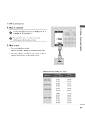
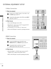
HDMI supports both audio and video. ( ) 2. How to use I Select the HDMI1 or HDMI2 input source on the TV using the INPUT button on the TV. 2 No separated audio connection is necessary. HDMI IN RGB IN RGB(PC) AUDIO (RGB/D 2 2 1 1 HDMI/DVI IN COMPONENT IN VIDEO 1 HDMI-DTV OUTPUT HDMI1/DVI-...
HDMI supports both audio and video. ( ) 2. How to use I Select the HDMI1 or HDMI2 input source on the TV using the INPUT button on the TV. 2 No separated audio connection is necessary. HDMI IN RGB IN RGB(PC) AUDIO (RGB/D 2 2 1 1 HDMI/DVI IN COMPONENT IN VIDEO 1 HDMI-DTV OUTPUT HDMI1/DVI-...
Owner's Manual
Page 20
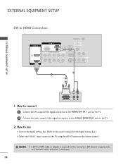
... the audio output of the digital set -top box. (Refer to the AUDIO (RGB/DVI) jack on the TV. 2. DVI doesn't support audio, so a separate audio connection is required for the digital set-top box.) I Turn on the digital set -top box to the ...owner's manual for this connection. How to use I Select the HDMI1 input source on the TV using the INPUT button on the remote control. ! AV IN 1 EXTERNAL EQUIPMENT SETUP EXTERNAL EQUIPMENT SETUP DVI to HDMI cable or adapter is necessary. 18...
... the audio output of the digital set -top box. (Refer to the AUDIO (RGB/DVI) jack on the TV. 2. DVI doesn't support audio, so a separate audio connection is required for the digital set-top box.) I Turn on the digital set -top box to the ...owner's manual for this connection. How to use I Select the HDMI1 input source on the TV using the INPUT button on the remote control. ! AV IN 1 EXTERNAL EQUIPMENT SETUP EXTERNAL EQUIPMENT SETUP DVI to HDMI cable or adapter is necessary. 18...
Owner's Manual
Page 21
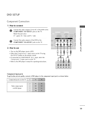
... to the component input ports as shown below. I Select the Component 1 input source on the TV using the INPUT button on the TV. Component ports on the TV Y PB PR Video output ports on the TV. RGB IN RGB(PC) AUDIO REM (RGB/DVI) SERVICE CONT 2 Connect the audio outputs of...DVD to the COMPONENT IN AUDIO1 jacks on DVD player Y PB PR Y B-Y R-Y Y Cb Cr Y Pb Pr 19 COMPONENT IN 2 RS (CONTR 2. I Turn on the TV. DVD SETUP Component Connection 1. Match the jack colors IN (Y = green, PB = blue, and PR = red). How to use 1 VI IN VIDEO AUDIO S-VI ( )...
... to the component input ports as shown below. I Select the Component 1 input source on the TV using the INPUT button on the TV. Component ports on the TV Y PB PR Video output ports on the TV. RGB IN RGB(PC) AUDIO REM (RGB/DVI) SERVICE CONT 2 Connect the audio outputs of...DVD to the COMPONENT IN AUDIO1 jacks on DVD player Y PB PR Y B-Y R-Y Y Cb Cr Y Pb Pr 19 COMPONENT IN 2 RS (CONTR 2. I Turn on the TV. DVD SETUP Component Connection 1. Match the jack colors IN (Y = green, PB = blue, and PR = red). How to use 1 VI IN VIDEO AUDIO S-VI ( )...
Owner's Manual
Page 22
I Select the HDMI1 or HDMI2 input source on the TV using the INPUT button on the TV. 2 No separated audio connection is necessary. How to the DVD player's manual for operating instructions. HDMI suppo( rt)s both audio and video. 2. HDMI IN RGB ... the HDMI output of the DVD to the AUDIO input jacks on the DVD player, insert a DVD. I Turn on the TV. 2. I Refer to use I Select the A V 1 input source on the TV using the INPUT button on the remote control. How to the DVD player's manual for operating instructions. How to connect 1 Connect...
I Select the HDMI1 or HDMI2 input source on the TV using the INPUT button on the TV. 2 No separated audio connection is necessary. How to the DVD player's manual for operating instructions. HDMI suppo( rt)s both audio and video. 2. HDMI IN RGB ... the HDMI output of the DVD to the AUDIO input jacks on the DVD player, insert a DVD. I Turn on the TV. 2. I Refer to use I Select the A V 1 input source on the TV using the INPUT button on the remote control. How to the DVD player's manual for operating instructions. How to connect 1 Connect...


