Owner's Manual
Page 3
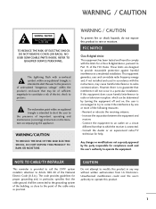
... be determined by turning the equipment off and on a circuit different from LG Electronics. Connect the equipment to Part 15 of important operating and maintenance (servicing) instructions in a residential installation. WARNING / CAUTION To prevent fire or shock hazards, do not expose this product 1 NO USER SERVICEABLE PARTS INSIDE. Consult the dealer or an experienced radio/TV technician for a Class B digital device, pursuant...
... be determined by turning the equipment off and on a circuit different from LG Electronics. Connect the equipment to Part 15 of important operating and maintenance (servicing) instructions in a residential installation. WARNING / CAUTION To prevent fire or shock hazards, do not expose this product 1 NO USER SERVICEABLE PARTS INSIDE. Consult the dealer or an experienced radio/TV technician for a Class B digital device, pursuant...
Owner's Manual
Page 6
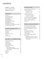
... CONTROL Auto Volume Leveler (Auto Volume 49 Preset Sound Settings (Sound Mode) 50 Sound Setting Adjustment - Channel Editing 36 Input List 37 Input Label 38 Key Lock 39 4 PICTURE CONTROL Picture Size (Aspect Ratio) Control 40 Preset Picture Settings - Picture Mode - Digital Broadcasting System Captions 59 - User Mode 43 - Caption Option 60 CONTENTS WARNING / CAUTION 1 SAFETY INSTRUCTIONS 2 FEATURE OF THIS TV 6 PREPARATION Accessories 7 Front Panel Information 8 Back Panel Information 9 Stand Installation 10 VESA Wall Mounting 11 Desktop Pedestal Installation 11 Cable...
... CONTROL Auto Volume Leveler (Auto Volume 49 Preset Sound Settings (Sound Mode) 50 Sound Setting Adjustment - Channel Editing 36 Input List 37 Input Label 38 Key Lock 39 4 PICTURE CONTROL Picture Size (Aspect Ratio) Control 40 Preset Picture Settings - Picture Mode - Digital Broadcasting System Captions 59 - User Mode 43 - Caption Option 60 CONTENTS WARNING / CAUTION 1 SAFETY INSTRUCTIONS 2 FEATURE OF THIS TV 6 PREPARATION Accessories 7 Front Panel Information 8 Back Panel Information 9 Stand Installation 10 VESA Wall Mounting 11 Desktop Pedestal Installation 11 Cable...
Owner's Manual
Page 11
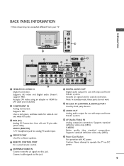
.../DVI) 4 SERVICE ANTENNA/ 5 CABLE IN DIGITAL REMOTE AUDIO OUT CONTROL IN OPTICAL 6 7 COMPONENT IN 2 2 1 1 HDMI/DVI IN VIDEO AUDIO 2 1 HDMI/DVI IN, HDMI IN Digital Connection. Supports standard definition video only (480i). 11 Power Cord Socket For operation with amps and home theater systems. 10 AV (Audio/Video) IN Analog composite connection. Supports HD video and Digital audio. Uses a red, green, and blue cable for video & red and white for software updates. 5 REMOTE CONTROL PORT For a wired remote control. AUDIO (RGB/DVI) 1/8" headphone jack for analog PC audio input...
.../DVI) 4 SERVICE ANTENNA/ 5 CABLE IN DIGITAL REMOTE AUDIO OUT CONTROL IN OPTICAL 6 7 COMPONENT IN 2 2 1 1 HDMI/DVI IN VIDEO AUDIO 2 1 HDMI/DVI IN, HDMI IN Digital Connection. Supports standard definition video only (480i). 11 Power Cord Socket For operation with amps and home theater systems. 10 AV (Audio/Video) IN Analog composite connection. Supports HD video and Digital audio. Uses a red, green, and blue cable for video & red and white for software updates. 5 REMOTE CONTROL PORT For a wired remote control. AUDIO (RGB/DVI) 1/8" headphone jack for analog PC audio input...
Owner's Manual
Page 18
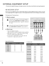
... IN the set. Component Connection 1. How to use I Turn on the remote control. EXTERNAL EQUIPMENT SETUP HD RECEIVER SETUP This TV can receive Digital Over-the-air/Cable signals without an external digital set -top box to 1 the COMPONENT IN AUDIO 1 jacks on the TV. operation) I Select the Component 1 input source on the TV using the INPUT button on the digital set-top box. (Refer to the owner's manual for the digital set-top box. EXTERNAL EQUIPMENT SETUP I To prevent the equipment damage, never plug in any power cords until...
... IN the set. Component Connection 1. How to use I Turn on the remote control. EXTERNAL EQUIPMENT SETUP HD RECEIVER SETUP This TV can receive Digital Over-the-air/Cable signals without an external digital set -top box to 1 the COMPONENT IN AUDIO 1 jacks on the TV. operation) I Select the Component 1 input source on the TV using the INPUT button on the digital set-top box. (Refer to the owner's manual for the digital set-top box. EXTERNAL EQUIPMENT SETUP I To prevent the equipment damage, never plug in any power cords until...
Owner's Manual
Page 19
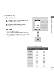
EXTERNAL EQUIPMENT SETUP HDMI Connection 1. How to HDMI/DVI IN 1 or HDMI IN 2 jack on the remote control. HDMI IN RGB IN RGB(PC) AUDIO (RGB/D 2 2 1 1 HDMI/DVI IN COMPONENT IN VIDEO 1 HDMI-DTV OUTPUT HDMI1/DVI-DTV, HDMI2-DTV mode Resolution Horizontal Vertical... use I Turn on the digital set-top box. (Refer to the owner's manual for the digital set -top box to connect 1 Connect the digital set -top box.) I Select the HDMI1 or HDMI2 input source on the TV using the INPUT button on the TV. 2 No separated audio connection is necessary. HDMI supports both audio and video...
EXTERNAL EQUIPMENT SETUP HDMI Connection 1. How to HDMI/DVI IN 1 or HDMI IN 2 jack on the remote control. HDMI IN RGB IN RGB(PC) AUDIO (RGB/D 2 2 1 1 HDMI/DVI IN COMPONENT IN VIDEO 1 HDMI-DTV OUTPUT HDMI1/DVI-DTV, HDMI2-DTV mode Resolution Horizontal Vertical... use I Turn on the digital set-top box. (Refer to the owner's manual for the digital set -top box to connect 1 Connect the digital set -top box.) I Select the HDMI1 or HDMI2 input source on the TV using the INPUT button on the TV. 2 No separated audio connection is necessary. HDMI supports both audio and video...
Owner's Manual
Page 20
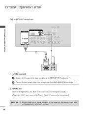
... INPUT button on the remote control. ! NOTE G A DVI to the AUDIO (RGB/DVI) jack on the digital set-top box. (Refer to the owner's manual for this connection. How to connect 1 Connect the DVI output of the digital set-top box to the HDMI/DVI IN 1 jack on the TV. 2 Connect the audio output of the digital set -top box.) I Turn on the TV. 2. How to HDMI Connection HDMI IN ANTENNA/ CABLE IN RGB IN DIGITAL RGB(PC) AUDIO REMOTE AUDIO OUT (RGB/DVI) SERVICE CONTROL IN OPTICAL 2 2 1 1 HDMI/DVI IN COMPONENT IN RS-232C IN (CONTROL & SERVICE) AUDIO OUT VIDEO AUDIO S-VIDEO VIDEO...
... INPUT button on the remote control. ! NOTE G A DVI to the AUDIO (RGB/DVI) jack on the digital set-top box. (Refer to the owner's manual for this connection. How to connect 1 Connect the DVI output of the digital set-top box to the HDMI/DVI IN 1 jack on the TV. 2 Connect the audio output of the digital set -top box.) I Turn on the TV. 2. How to HDMI Connection HDMI IN ANTENNA/ CABLE IN RGB IN DIGITAL RGB(PC) AUDIO REMOTE AUDIO OUT (RGB/DVI) SERVICE CONTROL IN OPTICAL 2 2 1 1 HDMI/DVI IN COMPONENT IN RS-232C IN (CONTROL & SERVICE) AUDIO OUT VIDEO AUDIO S-VIDEO VIDEO...
Owner's Manual
Page 23
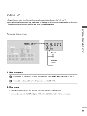
... VCR and TV. EXTERNAL EQUIPMENT SETUP VCR SETUP I Set VCR output switch to 3 or 4 and then tune TV to the same channel number. How to connect 1 Connect the RF antenna out socket of the VCR to the ANTENNA/CABLE IN socket on the VCR. (Refer to the VCR owner's manual.) 21 ( ) I If the 4:3 picture format is not covered by warranty. ( ) Antenna Connection ANTENNA/ CABLE IN GB IN DIGITAL AUDIO REMOTE AUDIO OUT (RGB/DVI) SERVICE CONTROL IN OPTICAL MPONENT IN RS-232C IN (CONTROL & SERVICE) AUDIO OUT EO AUDIO S-VIDEO VIDEO (MONO) AUDIO...
... VCR and TV. EXTERNAL EQUIPMENT SETUP VCR SETUP I Set VCR output switch to 3 or 4 and then tune TV to the same channel number. How to connect 1 Connect the RF antenna out socket of the VCR to the ANTENNA/CABLE IN socket on the VCR. (Refer to the VCR owner's manual.) 21 ( ) I If the 4:3 picture format is not covered by warranty. ( ) Antenna Connection ANTENNA/ CABLE IN GB IN DIGITAL AUDIO REMOTE AUDIO OUT (RGB/DVI) SERVICE CONTROL IN OPTICAL MPONENT IN RS-232C IN (CONTROL & SERVICE) AUDIO OUT EO AUDIO S-VIDEO VIDEO (MONO) AUDIO...
Owner's Manual
Page 28
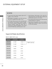
... mode, there may not work if a HDMI to be positioned on the graphics card, DOS mode may be noise associated with the resolution, vertical pattern, contrast or brightness. EXTERNAL EQUIPMENT SETUP EXTERNAL EQUIPMENT SETUP ! G Depending on the screen properly. The fixed image could become permanently imprinted on the graphics card, some resolution settings may not allow the image to DVI Cable is separate. Supported Display Specifications RGB-PC, HDMI1/DVI-PC mode Resolution...
... mode, there may not work if a HDMI to be positioned on the graphics card, DOS mode may be noise associated with the resolution, vertical pattern, contrast or brightness. EXTERNAL EQUIPMENT SETUP EXTERNAL EQUIPMENT SETUP ! G Depending on the screen properly. The fixed image could become permanently imprinted on the graphics card, some resolution settings may not allow the image to DVI Cable is separate. Supported Display Specifications RGB-PC, HDMI1/DVI-PC mode Resolution...
Owner's Manual
Page 29
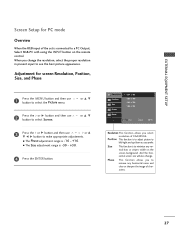
... G button and then use or D E F G button to make appropriate adjustments. EXTERNAL EQUIPMENT SETUP Screen Setup for screen Resolution, Position, Size, and Phase 1 Press the MENU button and then use button to select the Picture menu. Phase This function allows you change . Size This function is to adjust picture to see the best picture appearance. And the horizontal screen size will also change the resolution, select the proper resolution in present input to left/right and up/down as you select resolution of the set...
... G button and then use or D E F G button to make appropriate adjustments. EXTERNAL EQUIPMENT SETUP Screen Setup for screen Resolution, Position, Size, and Phase 1 Press the MENU button and then use button to select the Picture menu. Phase This function allows you change . Size This function is to adjust picture to see the best picture appearance. And the horizontal screen size will also change the resolution, select the proper resolution in present input to left/right and up/down as you select resolution of the set...
Owner's Manual
Page 31
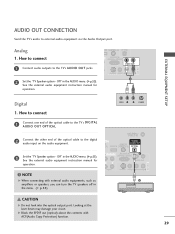
... you can turn the TV speakers off in the menu. (G p.53) VIDEO L R S-VIDEO ANTENNA/ CABLE IN DIGITAL O REMOTE AUDIO OUT VI) SERVICE CONTROL IN OPTICAL N RS-232C IN 1 (CONTROL & SERVICE) AUDIO OUT AUDIO S-VIDEO VIDEO (MONO) AUDIO 2 AV IN 1 CAUTION G Do not look into the optical output port. How to connect 1 Connect one end of the optical cable to the TV's DIGITAL AUDIO OUT OPTICAL. 2 Connect the other end of the optical cable to external audio equipment via the Audio Output port. Analog 1. See the external audio equipment instruction manual for operation. NOTE G When...
... you can turn the TV speakers off in the menu. (G p.53) VIDEO L R S-VIDEO ANTENNA/ CABLE IN DIGITAL O REMOTE AUDIO OUT VI) SERVICE CONTROL IN OPTICAL N RS-232C IN 1 (CONTROL & SERVICE) AUDIO OUT AUDIO S-VIDEO VIDEO (MONO) AUDIO 2 AV IN 1 CAUTION G Do not look into the optical output port. How to connect 1 Connect one end of the optical cable to the TV's DIGITAL AUDIO OUT OPTICAL. 2 Connect the other end of the optical cable to external audio equipment via the Audio Output port. Analog 1. See the external audio equipment instruction manual for operation. NOTE G When...
Owner's Manual
Page 32
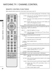
... off automatically. INPUT External input modes rotate in regular sequence. TIMER Select the amount of time before your preference. G p.36 MUTE Switch the sound on -screen displays and return to TV viewing from any menu. VCR/DVD Control buttons Control video cassette recorders or DVD players. G p.41 SOUND Selects the factory preset sound for multiple program channels such as 2-1, 2-2, etc. G p.50 SAP Analog mode: Selects MTS sound (Mono, Stereo, or a SAP) G p.54 DTV mode: Changes the audio language. G p.64 FAV VOL MUTE P A CH G E VOLUME UP Increase/decrease...
... off automatically. INPUT External input modes rotate in regular sequence. TIMER Select the amount of time before your preference. G p.36 MUTE Switch the sound on -screen displays and return to TV viewing from any menu. VCR/DVD Control buttons Control video cassette recorders or DVD players. G p.41 SOUND Selects the factory preset sound for multiple program channels such as 2-1, 2-2, etc. G p.50 SAP Analog mode: Selects MTS sound (Mono, Stereo, or a SAP) G p.54 DTV mode: Changes the audio language. G p.64 FAV VOL MUTE P A CH G E VOLUME UP Increase/decrease...
Owner's Manual
Page 34
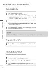
... TV is out. 3 When finished using the INPUT button on vacation, disconnect the power plug from the wall power outlet. WATCHING TV / CHANNEL CONTROL WATCHING TV / CHANNEL CONTROL TURNING ON TV 1 First, connect power cord correctly. I In standby mode to , even if the power cord is programmed to remember which power state it was last set to turn TV on, press the , INPUT, C H (D or E) button on the TV or press the POWER, INPUT, C H ( or + -), Number (0~9 ) button on the remote control.
... TV is out. 3 When finished using the INPUT button on vacation, disconnect the power plug from the wall power outlet. WATCHING TV / CHANNEL CONTROL WATCHING TV / CHANNEL CONTROL TURNING ON TV 1 First, connect power cord correctly. I In standby mode to , even if the power cord is programmed to remember which power state it was last set to turn TV on, press the , INPUT, C H (D or E) button on the TV or press the POWER, INPUT, C H ( or + -), Number (0~9 ) button on the remote control.
Owner's Manual
Page 42
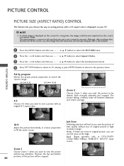
... or G button and then use or D E button to be cropped. J u s t S c a n operates only in original picture, you can see the noise at the edge. The picture taking a halfway trade off between alteration and screen coverage. 4:3 16:9 Adjust the picture horizontally, in high resolution image. Zoom 2 Choose Zoom 2 when you want the picture to select Aspect Ratio. NOTE G If a fixed image is displayed on the screen and remain visible. Set by warranty. However...
... or G button and then use or D E button to be cropped. J u s t S c a n operates only in original picture, you can see the noise at the edge. The picture taking a halfway trade off between alteration and screen coverage. 4:3 16:9 Adjust the picture horizontally, in high resolution image. Zoom 2 Choose Zoom 2 when you want the picture to select Aspect Ratio. NOTE G If a fixed image is displayed on the screen and remain visible. Set by warranty. However...
Owner's Manual
Page 43
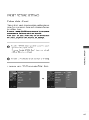
... save and return to adjust Picture Mode. Dynamic, Standard, M i l d Settings are preset for the optimum picture quality at the factory and are factory presets for picture settings available in the user menus. In the User1 and User2 modes only, user can use a preset, change each setting manually, or use the PICTURE menu to TV viewing. Picture Mode Color Temperature DB Advanced Aspect Ratio Picture Reset Screen : User1 : Cool : 16:9 Picture Mode G Color Temperature DB Advanced Aspect Ratio Picture Reset Screen Dynamic Standard Mild User 1 User 2 PICTURE CONTROL 41 I You can...
... save and return to adjust Picture Mode. Dynamic, Standard, M i l d Settings are preset for the optimum picture quality at the factory and are factory presets for picture settings available in the user menus. In the User1 and User2 modes only, user can use a preset, change each setting manually, or use the PICTURE menu to TV viewing. Picture Mode Color Temperature DB Advanced Aspect Ratio Picture Reset Screen : User1 : Cool : 16:9 Picture Mode G Color Temperature DB Advanced Aspect Ratio Picture Reset Screen Dynamic Standard Mild User 1 User 2 PICTURE CONTROL 41 I You can...
Owner's Manual
Page 60
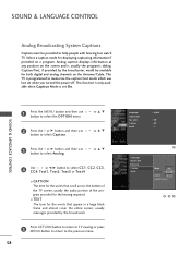
... to TV viewing or press M E N U button to return to select Analog. or D E SOUND & LANGUAGE CONTROL 2 Press the or G button and then use button to the previous menu. 58 Language Input Label Key Lock Caption Set ID : English : Off : Off : 1 Language Input Label Key Lock Caption Set ID 1 Mode On Analog Text1 Digital Service3 Digital Option 2 34 SOUND & LANGUAGE CONTROL Analog Broadcasting System Captions Caption must be available for both digital and analog channels on the Antenna/Cable. Analog caption displays information at any position on a program. This...
... to TV viewing or press M E N U button to return to select Analog. or D E SOUND & LANGUAGE CONTROL 2 Press the or G button and then use button to the previous menu. 58 Language Input Label Key Lock Caption Set ID : English : Off : Off : 1 Language Input Label Key Lock Caption Set ID 1 Mode On Analog Text1 Digital Service3 Digital Option 2 34 SOUND & LANGUAGE CONTROL Analog Broadcasting System Captions Caption must be available for both digital and analog channels on the Antenna/Cable. Analog caption displays information at any position on a program. This...
Owner's Manual
Page 68
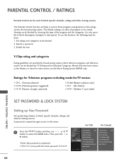
... specific channels, ratings, and external viewing sources. To use this menu. 1 Press the MENU button and then use the Movie Rating System (MPAA) only. Ratings for Television programs including made-for a time period. I The TV is required to gain access to block specific channels, ratings and other viewing sources. For USA For Canada Lock System : Off Set Password Block Channel Movie Rating TV Rating-Children TV Rating-General Downloadable Rating Input Block Lock...
... specific channels, ratings, and external viewing sources. To use this menu. 1 Press the MENU button and then use the Movie Rating System (MPAA) only. Ratings for Television programs including made-for a time period. I The TV is required to gain access to block specific channels, ratings and other viewing sources. For USA For Canada Lock System : Off Set Password Block Channel Movie Rating TV Rating-Children TV Rating-General Downloadable Rating Input Block Lock...
Owner's Manual
Page 74
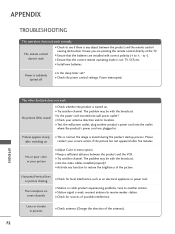
... the picture. The remote control doesn't work I Check to -). Power interrupted. The problem may be with the broadcast. I Is the sleep timer set : TV, VCR etc. Poor reception on contact your antenna direction and/or location. APPENDIX TROUBLESHOOTING The operation does not work . I Activate any object between the product and the VCR. I Adjust Color in pictures I Try another product's power cord into wall power outlet? No or poor color or poor picture I Check your service center...
... the picture. The remote control doesn't work I Check to -). Power interrupted. The problem may be with the broadcast. I Is the sleep timer set : TV, VCR etc. Poor reception on contact your antenna direction and/or location. APPENDIX TROUBLESHOOTING The operation does not work . I Activate any object between the product and the VCR. I Adjust Color in pictures I Try another product's power cord into wall power outlet? No or poor color or poor picture I Check your service center...
Owner's Manual
Page 78
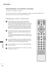
... the remote may not control all models. TV POWER DVD STB VCR RETURN MENU INPUT ENTER BRIGHT - When pressing the button, the light blinks at the same time for two seconds; After blinking twice, this code is successful. 4 Press the MENU button to repeat from step 2. 3 Enter the appropriate code from the code table on the following pages. TIMER BRIGHT + FAV VOL MUTE P CH A G E 123 456 789 0 FLASHBK ADJUST RATIO PICTURE SOUND SAP CC...
... the remote may not control all models. TV POWER DVD STB VCR RETURN MENU INPUT ENTER BRIGHT - When pressing the button, the light blinks at the same time for two seconds; After blinking twice, this code is successful. 4 Press the MENU button to repeat from step 2. 3 Enter the appropriate code from the code table on the following pages. TIMER BRIGHT + FAV VOL MUTE P CH A G E 123 456 789 0 FLASHBK ADJUST RATIO PICTURE SOUND SAP CC...
Owner's Manual
Page 82
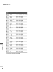
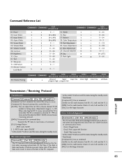
Remote control Button CH / + Remote control Button CH / - APPENDIX 80 Remote control Button TIMER Remote control Button ADJUST Remote control Button RATIO Remote control Button PICTURE Remote control Button SOUND Remote control Button SAP Remote control Button CC Remote control Button * Use this feature depending on your model. APPENDIX Code (Hexa) 08 43 0B 10-19 4C 1A 09 02 03 00 01 1E 40 41 07 06 44 5B E0 E1 0E CB 79 4D 52 0A 39 Function Note POWER Remote control Button (Power On/Off) MENU Remote control Button INPUT Remote control Button Number Key 0-9 Remote...
Remote control Button CH / + Remote control Button CH / - APPENDIX 80 Remote control Button TIMER Remote control Button ADJUST Remote control Button RATIO Remote control Button PICTURE Remote control Button SOUND Remote control Button SAP Remote control Button CC Remote control Button * Use this feature depending on your model. APPENDIX Code (Hexa) 08 43 0B 10-19 4C 1A 09 02 03 00 01 1E 40 41 07 06 44 5B E0 E1 0E CB 79 4D 52 0A 39 Function Note POWER Remote control Button (Power On/Off) MENU Remote control Button INPUT Remote control Button Number Key 0-9 Remote...
Owner's Manual
Page 85
...]: Use the small character, if set ID to read status of the PC computer. * In this format when receiving abnormal data from non-viable functions or communication errors. Power k 02. Screen Mute k 06. Volume Mute k 07. Adjustment range is controlled. Data1: Illegal Code Data2: Not supported function Data3: Wait more time * In this format when receiving normal data. Aspect Ratio k 05. Brightness k 10. Remote Control Lock Mode k a 0~1 15. Back Light...
...]: Use the small character, if set ID to read status of the PC computer. * In this format when receiving abnormal data from non-viable functions or communication errors. Power k 02. Screen Mute k 06. Volume Mute k 07. Adjustment range is controlled. Data1: Illegal Code Data2: Not supported function Data3: Wait more time * In this format when receiving normal data. Aspect Ratio k 05. Brightness k 10. Remote Control Lock Mode k a 0~1 15. Back Light...

