
Service Manual
Page 16
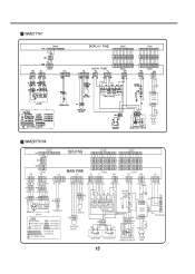
... 123 YL BL RD BK WH 1 2 3 4 2 3 3 2 4 1 5 WH BK BK 8 7 6 5 YL 1 2 WH 4 3 2 1 PLC MODEM PRESSURE SWITCH BN BK BK SB P T C SOLE NOID P T C BK GN WH DRAIN PUMP CIRCULATION PUMP DOOR LOCK SWITCH POWER CORD 15
... 123 YL BL RD BK WH 1 2 3 4 2 3 3 2 4 1 5 WH BK BK 8 7 6 5 YL 1 2 WH 4 3 2 1 PLC MODEM PRESSURE SWITCH BN BK BK SB P T C SOLE NOID P T C BK GN WH DRAIN PUMP CIRCULATION PUMP DOOR LOCK SWITCH POWER CORD 15
Service Manual
Page 18
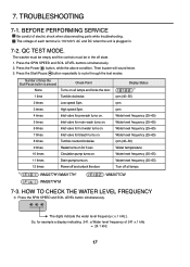
.... The digits indicate the water level frequency ( x.1 kHz ). TROUBLESHOOTING 7-1. The voltage of 241 x.1 kHz = 24.1 kHz 17 So, for 3 sec. 10 times Circulation pump turns on. 11 times Drain pump turns on. 12 times Power off state. 1. 7. The washer must be empty and the controls must be in . 7-2. Display Status rpm (40~50...
.... The digits indicate the water level frequency ( x.1 kHz ). TROUBLESHOOTING 7-1. The voltage of 241 x.1 kHz = 24.1 kHz 17 So, for 3 sec. 10 times Circulation pump turns on. 11 times Drain pump turns on. 12 times Power off state. 1. 7. The washer must be empty and the controls must be in . 7-2. Display Status rpm (40~50...
Service Manual
Page 31
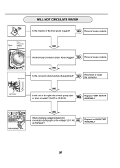
... foreign material. Connector NO Is the coil of the right side of the drain pump clogged? Hose Hose Connector (White) NO Are the Hose Connector and/or Hose clogged? WILL NOT CIRCULATE WATER Is the impeller of drain pump open or short circuited? (Coil R is the voltage 120 V AC, NO as the figure...
... foreign material. Connector NO Is the coil of the right side of the drain pump clogged? Hose Hose Connector (White) NO Are the Hose Connector and/or Hose clogged? WILL NOT CIRCULATE WATER Is the impeller of drain pump open or short circuited? (Coil R is the voltage 120 V AC, NO as the figure...

Service Manual
Page 39
Disassemble the pump assembly in arrow direction. Disassemble the cabinet cover. CAUTION • When assembling the heater, insert the heater into the heater clip on the bottom of ... heater is secure. Separate 2 connectors from the thermistor. Unplug the white connector from the heater. Loosen the nut and pull out the heater. Separate the pump hose, the bellows and the circulation hose assembly from the...
Disassemble the pump assembly in arrow direction. Disassemble the cabinet cover. CAUTION • When assembling the heater, insert the heater into the heater clip on the bottom of ... heater is secure. Separate 2 connectors from the thermistor. Unplug the white connector from the heater. Loosen the nut and pull out the heater. Separate the pump hose, the bellows and the circulation hose assembly from the...


