
Owner's Manual
Page 4
..., the damaged product can cause electric shock or fire. Keep small accessories out of the reach of mercury. On Disposal (Only, Hg lamp used LCD Monitor) The fluorescent lamp used in accordance to prevent scratching. Do not press on the screen for repair. Do not clean with a hand or sharp object... forward and hold it with both hands to the User's Guide. If you look at all times. Do not place the product face down. - Contact LG Customer Service for a long time may occur. (Do not use it to clean the front frame;wipe in and related problems are not covered by...
..., the damaged product can cause electric shock or fire. Keep small accessories out of the reach of mercury. On Disposal (Only, Hg lamp used LCD Monitor) The fluorescent lamp used in accordance to prevent scratching. Do not press on the screen for repair. Do not clean with a hand or sharp object... forward and hold it with both hands to the User's Guide. If you look at all times. Do not place the product face down. - Contact LG Customer Service for a long time may occur. (Do not use it to clean the front frame;wipe in and related problems are not covered by...

Owner's Manual
Page 5
Thank for the product. 4 Please make sure the following items are missing, contact your monitor. User must use shielded signal interface cables (D-sub 15 pin cable, DVI cable) with your dealer. User's Guide/Cards Power Cord (Depending on the country) ...
Thank for the product. 4 Please make sure the following items are missing, contact your monitor. User must use shielded signal interface cables (D-sub 15 pin cable, DVI cable) with your dealer. User's Guide/Cards Power Cord (Depending on the country) ...
Owner's Manual
Page 6
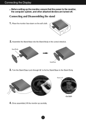
Stand Body Stand Base 3. Connecting the Display Before setting up carefully. 5 Connecting and Disassembling the stand 1. Once assembled, lift the monitor up the monitor, ensure that the power to the Stand Body. Turn the Stand Base Lock through 90˚ to fix the Stand Base to the monitor, the computer system, and other attached devices are turned off. Place the monitor face down on the soft cloth. 2. Base Lock 4. Assemble the Stand Base into the Stand Body in the correct direction.
Stand Body Stand Base 3. Connecting the Display Before setting up carefully. 5 Connecting and Disassembling the stand 1. Once assembled, lift the monitor up the monitor, ensure that the power to the Stand Body. Turn the Stand Base Lock through 90˚ to fix the Stand Base to the monitor, the computer system, and other attached devices are turned off. Place the monitor face down on the soft cloth. 2. Base Lock 4. Assemble the Stand Base into the Stand Body in the correct direction.

Owner's Manual
Page 7
If you can't release the Stand Base even the Locking Knob is at a release position, Please push the indicated knob down holding only the stand base. Do not carry the product upside down and retry it. 6. Locking Knob IMPORTANT This picture depicts the general model of connection. Connecting the Display 5. Pull out the Stand Base to separate the Stand Base from the items shown in the picture. Turn the Stand Base Lock through 90˚ to remove. The product may differ from the Stand Body. Your monitor may fall and get damaged or cause injury. 6
If you can't release the Stand Base even the Locking Knob is at a release position, Please push the indicated knob down holding only the stand base. Do not carry the product upside down and retry it. 6. Locking Knob IMPORTANT This picture depicts the general model of connection. Connecting the Display 5. Pull out the Stand Base to separate the Stand Base from the items shown in the picture. Turn the Stand Base Lock through 90˚ to remove. The product may differ from the Stand Body. Your monitor may fall and get damaged or cause injury. 6
Owner's Manual
Page 8
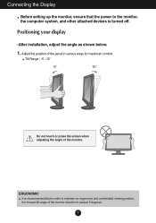
.... Adjust the position of the monitor should not exceed 5 degrees. 7 Positioning your display -After installation, adjust the angle as shown below. 1. Tilt Range : -5˚~15˚ -5 15 Do not touch or press the screen when adjusting the angle of the monitor. Connecting the Display Before setting ...up the monitor, ensure that the power to the monitor, the computer system, and other attached devices is recommended that in order to maintain an ergonomic ...
.... Adjust the position of the monitor should not exceed 5 degrees. 7 Positioning your display -After installation, adjust the angle as shown below. 1. Tilt Range : -5˚~15˚ -5 15 Do not touch or press the screen when adjusting the angle of the monitor. Connecting the Display Before setting ...up the monitor, ensure that the power to the monitor, the computer system, and other attached devices is recommended that in order to maintain an ergonomic ...
Owner's Manual
Page 9
... button to improve resolution. 8 This rear view represents a general model; Before setting up the monitor, ensure that the power to model. Connecting the Display W1943TS/W2043TE/W2243TE Connecting with optimal display settings.When the user connects the monitor for the first time, this function automatically adjusts the display to optimal settings for Macintosh...
... button to improve resolution. 8 This rear view represents a general model; Before setting up the monitor, ensure that the power to model. Connecting the Display W1943TS/W2043TE/W2243TE Connecting with optimal display settings.When the user connects the monitor for the first time, this function automatically adjusts the display to optimal settings for Macintosh...
Owner's Manual
Page 10
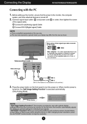
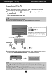
... the first time, this function automatically adjusts the display to turn the power on the supplied cable to model. Before setting up the monitor, ensure that the power to improve resolution. 9 your display may differ from the view as blurry screen, blurred letters, screen flicker ...model; A Connect D-sub(Analog signal) Cable NOTE This is needed to change the 15 pin high density (3 row) D-sub VGA connector on . When monitor power is turned on the front panel to optimal settings for Macintosh Mac adapter : For older Apple Macintosh use, a separate plug adapter is a simplified ...
... the first time, this function automatically adjusts the display to turn the power on the supplied cable to model. Before setting up the monitor, ensure that the power to improve resolution. 9 your display may differ from the view as blurry screen, blurred letters, screen flicker ...model; A Connect D-sub(Analog signal) Cable NOTE This is needed to change the 15 pin high density (3 row) D-sub VGA connector on . When monitor power is turned on the front panel to optimal settings for Macintosh Mac adapter : For older Apple Macintosh use, a separate plug adapter is a simplified ...
Owner's Manual
Page 15
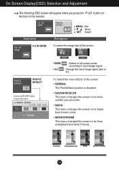
... the the front of the screen. button on Main menu 4:3 IN WIDE MENU : Exit : Move SET : Select Description To select the image size of the monitor. PHOTO EFFECT Use the AUTO/SET button to go to 4:3. WIDE 4:3 • WIDE • 4:3 : Switch to full screen mode according to input image signal. : Change...
... the the front of the screen. button on Main menu 4:3 IN WIDE MENU : Exit : Move SET : Select Description To select the image size of the monitor. PHOTO EFFECT Use the AUTO/SET button to go to 4:3. WIDE 4:3 • WIDE • 4:3 : Switch to full screen mode according to input image signal. : Change...
Owner's Manual
Page 16
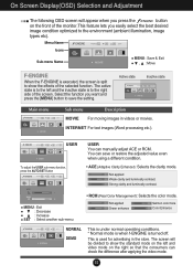
... right so that the consumers can check the difference after applying the video mode. 15 The active state is to the right side of the monitor.This feature lets you want and press the [MENU] button to the environment (ambient illumination, image types etc). Not applied Green enhance Salmon color tone...
... right so that the consumers can check the difference after applying the video mode. 15 The active state is to the right side of the monitor.This feature lets you want and press the [MENU] button to the environment (ambient illumination, image types etc). Not applied Green enhance Salmon color tone...
Owner's Manual
Page 17
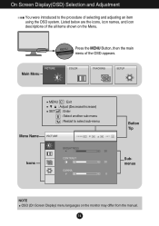
MENU : Exit : Adjust (Decrease/Increase) SET : Enter : Select another sub-menu : Restart to the procedure of selecting and adjusting an item using the OSD system. On Screen Display(OSD) Selection and Adjustment You were introduced to select sub-menu Menu Name Icons Button Tip Submenus NOTE OSD (On Screen Display) menu languages on the Menu. Main Menu Press the MENU Button, then the main menu of the all items shown on the monitor may differ from the manual. 16 Listed below are the icons, icon names, and icon descriptions of the OSD appears.
MENU : Exit : Adjust (Decrease/Increase) SET : Enter : Select another sub-menu : Restart to the procedure of selecting and adjusting an item using the OSD system. On Screen Display(OSD) Selection and Adjustment You were introduced to select sub-menu Menu Name Icons Button Tip Submenus NOTE OSD (On Screen Display) menu languages on the Menu. Main Menu Press the MENU Button, then the main menu of the all items shown on the monitor may differ from the manual. 16 Listed below are the icons, icon names, and icon descriptions of the OSD appears.

Owner's Manual
Page 18
...; 9300K: Slightly bluish white. Set your own red color levels. Set your own green color levels. Set your own gamma value. : -50 / 0 / 50 On the monitor, high gamma values display whitish images and low gamma values display blackish images. CONTRAST To adjust the contrast of the screen.
...; 9300K: Slightly bluish white. Set your own red color levels. Set your own green color levels. Set your own gamma value. : -50 / 0 / 50 On the monitor, high gamma values display whitish images and low gamma values display blackish images. CONTRAST To adjust the contrast of the screen.
Owner's Manual
Page 20
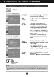
... card is an analog signal. 19 POWER INDICATOR Use this function when white and black colors are displayed. To adjust position of the monitor to ON or OFF. If you set OFF, it will go off. This function will automatically be enabled only when the input signal... screen. On Screen Display(OSD) Selection and Adjustment Main menu Sub menu Description SETUP W1943SS/W2043SE/W2243SE LANGUAGE OSD POSITION WHITE BALANCE W1943TS/W2043TE/W2243TE To choose the language in which the control names are present in order to provide the optimal image. Press the , buttons to...
... card is an analog signal. 19 POWER INDICATOR Use this function when white and black colors are displayed. To adjust position of the monitor to ON or OFF. If you set OFF, it will go off. This function will automatically be enabled only when the input signal... screen. On Screen Display(OSD) Selection and Adjustment Main menu Sub menu Description SETUP W1943SS/W2043SE/W2243SE LANGUAGE OSD POSITION WHITE BALANCE W1943TS/W2043TE/W2243TE To choose the language in which the control names are present in order to provide the optimal image. Press the , buttons to...
Owner's Manual
Page 23
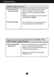
... it to install the display driver from the display driver CD (or diskette) that comes with your display. G Have you see an "Unrecognized monitor, Plug&Play (VESA DDC) monitor found" message? G The screen blinks. • Check if the screen is properly inserted in the slot. • Set the color setting higher than...
... it to install the display driver from the display driver CD (or diskette) that comes with your display. G Have you see an "Unrecognized monitor, Plug&Play (VESA DDC) monitor found" message? G The screen blinks. • Check if the screen is properly inserted in the slot. • Set the color setting higher than...
Owner's Manual
Page 32
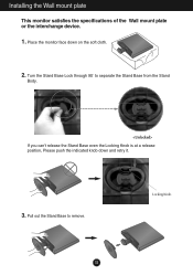
Installing the Wall mount plate This monitor satisfies the specifications of the Wall mount plate or the interchange device. 1. Pull out the Stand Base to separate the Stand Base from the Stand Body. If you can't release the Stand Base even the Locking Knob is at a release position, Please push the indicated knob down on the soft cloth. 2. Place the monitor face down and retry it. 3. Turn the Stand Base Lock through 90˚ to remove. Locking Knob 31
Installing the Wall mount plate This monitor satisfies the specifications of the Wall mount plate or the interchange device. 1. Pull out the Stand Base to separate the Stand Base from the Stand Body. If you can't release the Stand Base even the Locking Knob is at a release position, Please push the indicated knob down on the soft cloth. 2. Place the monitor face down and retry it. 3. Turn the Stand Base Lock through 90˚ to remove. Locking Knob 31


