Service Manual
Page 23
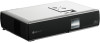
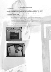
After you replace the lamp module, you remove the lamp cover. The switch interrupts power supply output to the projector if you should reset the lamp hour counter. If the lamp is ruptured or the lamp module is cracked or damaged, be careful of quartz or glass fragments that ...
After you replace the lamp module, you remove the lamp cover. The switch interrupts power supply output to the projector if you should reset the lamp hour counter. If the lamp is ruptured or the lamp module is cracked or damaged, be careful of quartz or glass fragments that ...

Service Manual
Page 34
... Y4,Y5 output frequency (Y4:16.257MHz, Y5:10MHz)) 3.chk MCLK(U37-5,130MHz) and DCLK(U39-5,40MHz) 4.chk U38 whether S/W inside or bad soldering 5.chk Reset IC (U40) 6. JT31 Electrical Debug Guide System no work No No data to DDP1000 No No im age No No im age when graphics is...
... Y4,Y5 output frequency (Y4:16.257MHz, Y5:10MHz)) 3.chk MCLK(U37-5,130MHz) and DCLK(U39-5,40MHz) 4.chk U38 whether S/W inside or bad soldering 5.chk Reset IC (U40) 6. JT31 Electrical Debug Guide System no work No No data to DDP1000 No No im age No No im age when graphics is...

Service Manual
Page 42
... layer (Fig-6): (Fig-6) Lamp layer 5.1 )Interpolation: De-interlace Mode 5.2) Filter: system auto select Filter. 5.3) Lamp Hour: value to tell you unit usage hours. 5.5) Data Reset: Reset all data. 5.6) Version: software version. 42 Never try to reset all data to tell you lamp usage hours. 5.4) Usage Hour: value to default include factory assign value.
... layer (Fig-6): (Fig-6) Lamp layer 5.1 )Interpolation: De-interlace Mode 5.2) Filter: system auto select Filter. 5.3) Lamp Hour: value to tell you unit usage hours. 5.5) Data Reset: Reset all data. 5.6) Version: software version. 42 Never try to reset all data to tell you lamp usage hours. 5.4) Usage Hour: value to default include factory assign value.

Service Manual
Page 85
... mirrors. Definitions 2.1 Blemish A blemish is an obstruction, reflection, or refraction of light that are similar in the image. 2.7 Reset boundary artifact The reset boundary artifact is visibly brighter than the neighboring rows of inspection (see Table 1). Streaks appear as a cluster. 2.6 Streaks Artifact ...stuck pixels sharing a common border or common point, also referred to be flickering asynchronously with digital imaging functionality based on the reset group boundaries that is visible, but appear at the mirror level. It is caused by a particle, scratch, or other ...
... mirrors. Definitions 2.1 Blemish A blemish is an obstruction, reflection, or refraction of light that are similar in the image. 2.7 Reset boundary artifact The reset boundary artifact is visibly brighter than the neighboring rows of inspection (see Table 1). Streaks appear as a cluster. 2.6 Streaks Artifact ...stuck pixels sharing a common border or common point, also referred to be flickering asynchronously with digital imaging functionality based on the reset group boundaries that is visible, but appear at the mirror level. It is caused by a particle, scratch, or other ...

Service Manual
Page 87
... CRITERIA 1. c. The diagonal size of the screen are colored a Microsoft Paintbrush gray 30 (green, red, and blue set to nominal. f. Refer to Figure 1 for the reset boundary artifact. NOTE: If linear degamma is not used then the Microsoft Paintbrush values must be adjusted to match the degamma table being used in...
... CRITERIA 1. c. The diagonal size of the screen are colored a Microsoft Paintbrush gray 30 (green, red, and blue set to nominal. f. Refer to Figure 1 for the reset boundary artifact. NOTE: If linear degamma is not used then the Microsoft Paintbrush values must be adjusted to match the degamma table being used in...

Service Manual
Page 88
...Notes: 1. No Eyecatcher or border artifact will be the projected image tests referenced in Section 3. Major Blemish Two Zone Screen 14 3 Reset Gray 30 boundary artifact 4 Eyecatcher Gray 10 Border Artifacts 5 Streaks Blue 60 Gray 10 White 6 Projected Any screen Images 1. No ...Active Area 3. __ 1 bright pixel in addition to the artifact itself. 2. 3. 4. 5. 6. Non-Critical Zone Critical Zone 25% Figure 1. No reset boundary artifact will be inspected in accordance with the conditions of the window artifact in the POM 4. __ 3 dark pixels 5. __ 6 minor blemishes 6....
...Notes: 1. No Eyecatcher or border artifact will be the projected image tests referenced in Section 3. Major Blemish Two Zone Screen 14 3 Reset Gray 30 boundary artifact 4 Eyecatcher Gray 10 Border Artifacts 5 Streaks Blue 60 Gray 10 White 6 Projected Any screen Images 1. No ...Active Area 3. __ 1 bright pixel in addition to the artifact itself. 2. 3. 4. 5. 6. Non-Critical Zone Critical Zone 25% Figure 1. No reset boundary artifact will be inspected in accordance with the conditions of the window artifact in the POM 4. __ 3 dark pixels 5. __ 6 minor blemishes 6....

Service Manual
Page 100
... in lower level of MENU OSD. Different MENU between RGB(PC) and AV(Video /S-Video) case : RGB ( PC ) VIDEO menu Contrast Brightness Color R Color G Color B Reset Range 0 ~ 100 0 ~ 100 0 ~ 100 0 ~ 100 0 ~ 100 Press Enter to clear MENU OSD by pressing Menu key in the first step of menu) Enter Key :... select items (move Cursor ) or adjust items (in the last selected mode when projector is turned on the position of VIDEO Menu be able to Reset 26 adjust items or select items by Volume +/ -, JOYSTICK be able to enter the lower level of menu by pressing Volume (-) key or pushing ...
... in lower level of MENU OSD. Different MENU between RGB(PC) and AV(Video /S-Video) case : RGB ( PC ) VIDEO menu Contrast Brightness Color R Color G Color B Reset Range 0 ~ 100 0 ~ 100 0 ~ 100 0 ~ 100 0 ~ 100 Press Enter to clear MENU OSD by pressing Menu key in the first step of menu) Enter Key :... select items (move Cursor ) or adjust items (in the last selected mode when projector is turned on the position of VIDEO Menu be able to Reset 26 adjust items or select items by Volume +/ -, JOYSTICK be able to enter the lower level of menu by pressing Volume (-) key or pushing ...

Service Manual
Page 101
case : AV ( VIDEO / S-VIDEO ) / HD VIDEO menu Range Contrast 0 ~ 100 Brightness 0 ~ 100 Color 0 ~ 100 Tint -50 ~ +50 Reset Press Enter to Reset Video sub-menu OSD Display time : Until being cleared. 2.3.3.2 POSITION Menu selected by pressing Volume (+) key or pushing JOYSTICK right on the position of POSITION ...
case : AV ( VIDEO / S-VIDEO ) / HD VIDEO menu Range Contrast 0 ~ 100 Brightness 0 ~ 100 Color 0 ~ 100 Tint -50 ~ +50 Reset Press Enter to Reset Video sub-menu OSD Display time : Until being cleared. 2.3.3.2 POSITION Menu selected by pressing Volume (+) key or pushing JOYSTICK right on the position of POSITION ...

Service Manual
Page 136
... DDP1000 will activate. 4.. High Low Indicate lamp off . JT31 Normal Lamp off Sequence Signal RESETZ LAMPEN LAMPLIT Voltage Change Description High Low DDP1000 goes into a reset state. LAMPEN Low High LAMPLITZ High Low LAMPLIT Low High Lamp lights up.
... DDP1000 will activate. 4.. High Low Indicate lamp off . JT31 Normal Lamp off Sequence Signal RESETZ LAMPEN LAMPLIT Voltage Change Description High Low DDP1000 goes into a reset state. LAMPEN Low High LAMPLITZ High Low LAMPLIT Low High Lamp lights up.

Service Manual
Page 152
...,Y5 output frequency (Y4:16.257MHz, Y5:10MHz)) 3.chk MCLK(U37-5,130MHz) and DCLK(U39-5,40M Hz) 4.chk U38 whether S/W inside or bad soldering 5.chk Reset IC (U40) 6. RN104) [video input] 3.chk U1and its peripherals (as above block) 1.chk DDP1000 debug guide 1.chk D_SUB cable and J103 2.chk VSYNC(U103-4),HSYNC...
...,Y5 output frequency (Y4:16.257MHz, Y5:10MHz)) 3.chk MCLK(U37-5,130MHz) and DCLK(U39-5,40M Hz) 4.chk U38 whether S/W inside or bad soldering 5.chk Reset IC (U40) 6. RN104) [video input] 3.chk U1and its peripherals (as above block) 1.chk DDP1000 debug guide 1.chk D_SUB cable and J103 2.chk VSYNC(U103-4),HSYNC...

Service Manual
Page 158
... A12 A11 A10 A9 A8 A7 A6 A5 A4 A3 A2 A1 A0 PUM-ARSTZ FL-OEZ FL-WEZ FL-CSZ PUM-ARSTZ P3P3V B4 RESET F6 BYTE G1 A4 F1 OE WE CE VDD G4 DQ15/A-1 DG14 DG13 DG12 DG11 DG10 DG9 DG8 DG7 DG6 DG5 DG4 DG3 DG2 DG1...
... A12 A11 A10 A9 A8 A7 A6 A5 A4 A3 A2 A1 A0 PUM-ARSTZ FL-OEZ FL-WEZ FL-CSZ PUM-ARSTZ P3P3V B4 RESET F6 BYTE G1 A4 F1 OE WE CE VDD G4 DQ15/A-1 DG14 DG13 DG12 DG11 DG10 DG9 DG8 DG7 DG6 DG5 DG4 DG3 DG2 DG1...

Service Manual
Page 170
... 10MHZ U17-X1 U17-X2 R211 1 8 X1 X2 GND 3 ICS501 820K C256 10P J C257 10P J P5V C258 0.1U Z U40 1 NC VDD 5 2 VSS 3 NC RES 4 R213 RESET-I RESET V6300L 1K R215 2K B R218 2K U41 1 2 3 4 NC NC NC GND VCC WP SCL SDA 8 7 6 5 AT24C16 16K SCL SDA P3P3V C259 0.1U Z Benq Corporation Project...
... 10MHZ U17-X1 U17-X2 R211 1 8 X1 X2 GND 3 ICS501 820K C256 10P J C257 10P J P5V C258 0.1U Z U40 1 NC VDD 5 2 VSS 3 NC RES 4 R213 RESET-I RESET V6300L 1K R215 2K B R218 2K U41 1 2 3 4 NC NC NC GND VCC WP SCL SDA 8 7 6 5 AT24C16 16K SCL SDA P3P3V C259 0.1U Z Benq Corporation Project...

Service Manual
Page 171
... 2N3904 1 P5V R617 10K R602 47 R603 47 R614 4.7K Q109 1 1 Q108 2N3904 2N3904 SCL SDA ALERT C268 U43 14 12 SMBCLK SMBDATA 11 ALERT 6 RESET 1 OUT1 10 FG1 9 CLK VCC VCC 15 2 DXP1 3 DXN 4 DXP2 5 OUT2 FG2 GND GND 16 13 7 8 10K F AN1-B C263 2200P K F AN1-E C264 2200P K F AN2-BR224...
... 2N3904 1 P5V R617 10K R602 47 R603 47 R614 4.7K Q109 1 1 Q108 2N3904 2N3904 SCL SDA ALERT C268 U43 14 12 SMBCLK SMBDATA 11 ALERT 6 RESET 1 OUT1 10 FG1 9 CLK VCC VCC 15 2 DXP1 3 DXN 4 DXP2 5 OUT2 FG2 GND GND 16 13 7 8 10K F AN1-B C263 2200P K F AN1-E C264 2200P K F AN2-BR224...

Service Manual
Page 176
TSOU 5 4 3 2 D D-FLIP RESETZ OPEN R624 0 P3P3V U209A 14 2 3 SN74HC74PWR 7 VCC D CLK GND Q5 Q6 R640 0 RESETQ P3P3V U211 1 4 2 P5V 74AHC1G32GW C U208 2 4 74V1G14S RESET R625 0 OPEN P3P3V LAMPLIT-PW R627 C603 0.1U K 100 LAMPLIT U210 P3P3V RESET_PW 1 4 2 74AHC1G08 1N4148 2 D202 1 R620 240K P5V U206 2 P5V U207 4 2 C605 4 1 2 74V1G14S 74V1G14S ...
TSOU 5 4 3 2 D D-FLIP RESETZ OPEN R624 0 P3P3V U209A 14 2 3 SN74HC74PWR 7 VCC D CLK GND Q5 Q6 R640 0 RESETQ P3P3V U211 1 4 2 P5V 74AHC1G32GW C U208 2 4 74V1G14S RESET R625 0 OPEN P3P3V LAMPLIT-PW R627 C603 0.1U K 100 LAMPLIT U210 P3P3V RESET_PW 1 4 2 74AHC1G08 1N4148 2 D202 1 R620 240K P5V U206 2 P5V U207 4 2 C605 4 1 2 74V1G14S 74V1G14S ...

User Guide
Page 18
... the control panel of the projector or the remote control. Main Menu VIDEO Contrast YPBPR Brightness Video Color S-Video Tint SubMenu Reset Contrast Brightness PC (RGB) Color R Color G Color B Reset POSITION SPECIAL TRACKING Keystone Zoom Resize Horizontal Vertical Keystone Zoom Resize Language Flip Horizontal Flip Vertical Blank Image Lamp Time Language Flip...
... the control panel of the projector or the remote control. Main Menu VIDEO Contrast YPBPR Brightness Video Color S-Video Tint SubMenu Reset Contrast Brightness PC (RGB) Color R Color G Color B Reset POSITION SPECIAL TRACKING Keystone Zoom Resize Horizontal Vertical Keystone Zoom Resize Language Flip Horizontal Flip Vertical Blank Image Lamp Time Language Flip...

User Guide
Page 19
... the brightness of difference between dark and light in the image. Adjusts the image to the factory preset values. Brightness Color Tint Color R Color G Color B Reset Increases or decreases the color range of the image. *This function is only available when the input mode is PC. DLP Personal Projector 15 Increases...
... the brightness of difference between dark and light in the image. Adjusts the image to the factory preset values. Brightness Color Tint Color R Color G Color B Reset Increases or decreases the color range of the image. *This function is only available when the input mode is PC. DLP Personal Projector 15 Increases...

