
Service Manual
Page 6
Upper case Lamp Module Ballast Module Main Board Front Fan Lens 6 To see exploded views of the projector. 4. The illustration on the next page shows the parts visible from the front of the projector. Exploded View The top illustration shows the parts from the rear of the case parts, major components and optical engine.
Upper case Lamp Module Ballast Module Main Board Front Fan Lens 6 To see exploded views of the projector. 4. The illustration on the next page shows the parts visible from the front of the projector. Exploded View The top illustration shows the parts from the rear of the case parts, major components and optical engine.
Service Manual
Page 8
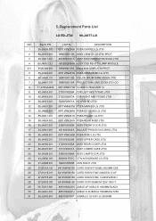
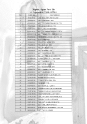
Replacement Parts List LG RD-JT30 99.J4977.L31 NO. 5. BenQ P/N LG P/N DESCRIPTION 1 55.J4906.001 6871VSN256A PCBA CHIP/BD LG JT30 2 60.J4910.001 3680V00113A ASSY LENS C1,C2 JT30 PROT 3 60.J4911.001 5018V00071A ASSY FOLD MIRROR MODULE JT30 4 60.J4912.CL1 6912B22006A ASSY CSD RD-JT30 LAMP MODULE 4-1 35.81J49.001 3680V00111A Glass front UVAR JT30 PROT 5 55.J4922.001...
Replacement Parts List LG RD-JT30 99.J4977.L31 NO. 5. BenQ P/N LG P/N DESCRIPTION 1 55.J4906.001 6871VSN256A PCBA CHIP/BD LG JT30 2 60.J4910.001 3680V00113A ASSY LENS C1,C2 JT30 PROT 3 60.J4911.001 5018V00071A ASSY FOLD MIRROR MODULE JT30 4 60.J4912.CL1 6912B22006A ASSY CSD RD-JT30 LAMP MODULE 4-1 35.81J49.001 3680V00111A Glass front UVAR JT30 PROT 5 55.J4922.001...

Service Manual
Page 18
... projector. Enter factory mode. 4.HDTV Color Adjustment Procedure Equipment: Pattern generator (VG-828) Lux meter ( CL-100) Procedure: (a). Offset adjustment: Black coordinate spec: Osram lamp Oshio lamp x0 0.281 0.01 0.313 0.01 y0 0.311 0.01 0.329 0.01 The variance of pattern generator : Timing : 480P(H:31.54 KHz,V:60.08 Hz) pattern : black...
... projector. Enter factory mode. 4.HDTV Color Adjustment Procedure Equipment: Pattern generator (VG-828) Lux meter ( CL-100) Procedure: (a). Offset adjustment: Black coordinate spec: Osram lamp Oshio lamp x0 0.281 0.01 0.313 0.01 y0 0.311 0.01 0.329 0.01 The variance of pattern generator : Timing : 480P(H:31.54 KHz,V:60.08 Hz) pattern : black...
Service Manual
Page 23
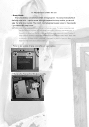
.... The switch interrupts power supply output to the projector if you should reset the lamp hour counter. How to cool before removing the lamp module. DO NOT touch any part of the lamp module that could cause personal injury. 1.Remove two screws of quartz or glass fragments that is a ...spring door. 2. Remove the 1 screw from your fingers will cause smudges and uneven heating of the projector. The lamp module becomes very hot when the projector is located at bottom of lamp surfaces, resulting in use. WARNING Allow the projector to disassemble the set 1. After you replace the...
.... The switch interrupts power supply output to the projector if you should reset the lamp hour counter. How to cool before removing the lamp module. DO NOT touch any part of the lamp module that could cause personal injury. 1.Remove two screws of quartz or glass fragments that is a ...spring door. 2. Remove the 1 screw from your fingers will cause smudges and uneven heating of the projector. The lamp module becomes very hot when the projector is located at bottom of lamp surfaces, resulting in use. WARNING Allow the projector to disassemble the set 1. After you replace the...

Service Manual
Page 24
Remove 4 screws under the projector of left side bezel, then remove it out of projector. 24 Grasp the handle on the lamp module and pull the module out of projector. 2. Covers 2.1 Side bezel 1. 3. Remove 4 screws under the projector of right side bezel, then remove it out of the lamp box. 2.
Remove 4 screws under the projector of left side bezel, then remove it out of projector. 24 Grasp the handle on the lamp module and pull the module out of projector. 2. Covers 2.1 Side bezel 1. 3. Remove 4 screws under the projector of right side bezel, then remove it out of the lamp box. 2.

Service Manual
Page 31
Remove 2 screws, then the lamp blower can be removed. 10. Optical engine 1. Remove 4 screws, then the optical engine can be removed. 31 9. Lamp Blower 1.
Remove 2 screws, then the lamp blower can be removed. 10. Optical engine 1. Remove 4 screws, then the optical engine can be removed. 31 9. Lamp Blower 1.

Service Manual
Page 33
... at right datum surface 4.Check Green color / If too green and over spec., change color drum 5.Change lamp 1.Check fold mirror position / re-align fold mirror to be closer to design position 2.Check lamp / Re-assembly lamp 1.Check projection lens clean / To clean projection lens 2.Check TIR and DMD clean / To clean TIR...
... at right datum surface 4.Check Green color / If too green and over spec., change color drum 5.Change lamp 1.Check fold mirror position / re-align fold mirror to be closer to design position 2.Check lamp / Re-assembly lamp 1.Check projection lens clean / To clean projection lens 2.Check TIR and DMD clean / To clean TIR...

Service Manual
Page 38
WARNING Note CW delay value in DMD layer and PbPr values in YpbPr Factory control before Upgrade the Software. 38 How to enter factory menu: 1) Press keypad key, Enter Power Off check state (Fig-1). (Fig-1). 2) Press keypad and key simultaneously, enter "Lamp Hour Info" layer (Fig-2). (Fig-2) Lamp Hours Info 3) Press keypad and key simultaneously again, then enter Factory menu. 13. Service Adjustment Guide 1.
WARNING Note CW delay value in DMD layer and PbPr values in YpbPr Factory control before Upgrade the Software. 38 How to enter factory menu: 1) Press keypad key, Enter Power Off check state (Fig-1). (Fig-1). 2) Press keypad and key simultaneously, enter "Lamp Hour Info" layer (Fig-2). (Fig-2) Lamp Hours Info 3) Press keypad and key simultaneously again, then enter Factory menu. 13. Service Adjustment Guide 1.

Service Manual
Page 41
...: Disable auto fan speed control and fix fan speed 3.2) PbPr: enter PbPr color control Layer. 3.1) FAN: enter system fan status info layer. Lamp Sensor: lamp sensor temperature Lamp Fan Speed: lamp fan speed in RPM Blower Speed: Blower fan speed in RPM Power Sensor: Power sensor temperature Power Fan Speed: Power fan speed in...
...: Disable auto fan speed control and fix fan speed 3.2) PbPr: enter PbPr color control Layer. 3.1) FAN: enter system fan status info layer. Lamp Sensor: lamp sensor temperature Lamp Fan Speed: lamp fan speed in RPM Blower Speed: Blower fan speed in RPM Power Sensor: Power sensor temperature Power Fan Speed: Power fan speed in...

Service Manual
Page 42
... color red. 4.4) Curtain Green: unit display full color green. 4.5) Curtain Blue: unit display full color blue. 5) Lamp layer (Fig-6): (Fig-6) Lamp layer 5.1 )Interpolation: De-interlace Mode 5.2) Filter: system auto select Filter. 5.3) Lamp Hour: value to tell you lamp usage hours. 5.4) Usage Hour: value to default include factory assign value. Never try to reset all...
... color red. 4.4) Curtain Green: unit display full color green. 4.5) Curtain Blue: unit display full color blue. 5) Lamp layer (Fig-6): (Fig-6) Lamp layer 5.1 )Interpolation: De-interlace Mode 5.2) Filter: system auto select Filter. 5.3) Lamp Hour: value to tell you lamp usage hours. 5.4) Usage Hour: value to default include factory assign value. Never try to reset all...

Service Manual
Page 77
.../V sync: TTL Level 3 7.0 Regulatory 8.0 Reliability 8.1 General Failure Def. 8.2 MTBF 8.3 Lamp lifetime 9.0 Power Requirements 9.1 Power Supply 9.2 Power Consumption 9.3 Power Connector 10.0 Panel and Lamp Specification 10.1 DMD Type 10.2 DMD Pixels 10.3 Aspect Ratio 10.4 Lamp Type 11.0 Compatibility 11.1 PC 11.2 Video 11.3 YPbPr 11.4 Plug and Play 12...23/EEC; Directive 89/336/EEC; Air 8KV, Contact 6KV, Criteria B Adhere to Appendix B 12000 hours except for DMD panel, Lamp and Fan 1000 (50% Brightness Maintenance) Adhere to Appendix D 0.55" DDR SVGA DMD chip 800x600 4:3 Ushio 150 Watt DC...
.../V sync: TTL Level 3 7.0 Regulatory 8.0 Reliability 8.1 General Failure Def. 8.2 MTBF 8.3 Lamp lifetime 9.0 Power Requirements 9.1 Power Supply 9.2 Power Consumption 9.3 Power Connector 10.0 Panel and Lamp Specification 10.1 DMD Type 10.2 DMD Pixels 10.3 Aspect Ratio 10.4 Lamp Type 11.0 Compatibility 11.1 PC 11.2 Video 11.3 YPbPr 11.4 Plug and Play 12...23/EEC; Directive 89/336/EEC; Air 8KV, Contact 6KV, Criteria B Adhere to Appendix B 12000 hours except for DMD panel, Lamp and Fan 1000 (50% Brightness Maintenance) Adhere to Appendix D 0.55" DDR SVGA DMD chip 800x600 4:3 Ushio 150 Watt DC...
Service Manual
Page 92
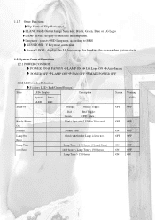
... image for blanking the screen when system starts 1.2 System Control Functions 1.2.1 POWER CONTROL POWER ON FAN ON LAMP ON LG Logo ON Auto Image POWER OFF LAMP OFF FAN OFF MAIN POWER OFF 1.2.2 LED's color Definition 3 colors LED (Red/Green/Orange) State LEDs Display Description Operatio Status n ...Error 1400 hours < Lamp Time < 1500 hours Lamp Time > 1500 hours Screen Warinng OSD OFF OFF OFF OFF ON OFF OFF OFF ON OFF ON OFF ON ON 1.1.7 Other Functions Flip Vertical/ Flip Horizontal BLANK Mode Output Image Selection: Black, Green, Blue or LG Logo LAMP TIME : display or ...
... image for blanking the screen when system starts 1.2 System Control Functions 1.2.1 POWER CONTROL POWER ON FAN ON LAMP ON LG Logo ON Auto Image POWER OFF LAMP OFF FAN OFF MAIN POWER OFF 1.2.2 LED's color Definition 3 colors LED (Red/Green/Orange) State LEDs Display Description Operatio Status n ...Error 1400 hours < Lamp Time < 1500 hours Lamp Time > 1500 hours Screen Warinng OSD OFF OFF OFF OFF ON OFF OFF OFF ON OFF ON OFF ON ON 1.1.7 Other Functions Flip Vertical/ Flip Horizontal BLANK Mode Output Image Selection: Black, Green, Blue or LG Logo LAMP TIME : display or ...

Service Manual
Page 93
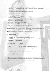
... OSD Position : the left corner of the screen. *You can change Temperature range according to your temperature condition. 1.2.2.1 Lamp On Error state If Lamp is not lit normally, display the LEDs above , you have to turn the projector off. 1.2.2.2 Lamp Time over Error LEDs above. Case 2: Over 1500 hours - Up Fn. Display the...
... OSD Position : the left corner of the screen. *You can change Temperature range according to your temperature condition. 1.2.2.1 Lamp On Error state If Lamp is not lit normally, display the LEDs above , you have to turn the projector off. 1.2.2.2 Lamp Time over Error LEDs above. Case 2: Over 1500 hours - Up Fn. Display the...
Service Manual
Page 94
... state If Fan is not operated normally, displays Fan On Error LEDs & Display Fan on Error OSD.. 1.2.2.6 Lamp Case_Open state If Lamp case is opened abnormally or when you replace used lamp with a new one, it displays lamp case_open LEDs . 1.2.3 WIRELESS MOUSE CONTROL 16 Direction, Left/Right Click, Drag Supports USB mouse we use...
... state If Fan is not operated normally, displays Fan On Error LEDs & Display Fan on Error OSD.. 1.2.2.6 Lamp Case_Open state If Lamp case is opened abnormally or when you replace used lamp with a new one, it displays lamp case_open LEDs . 1.2.3 WIRELESS MOUSE CONTROL 16 Direction, Left/Right Click, Drag Supports USB mouse we use...
Service Manual
Page 102
... SPECIAL Menu Selection Language According to MRS Flip Vertical Press Enter to Flip Flip Horizontal Press Enter to Flip Blank Image Black / Blue / Green / Logo Lamp Time 0 Hour VGA Text 640 400 / 720 400 ( only PC ) manually control 640 400 or 720 400 mode because two mode is very similar sync...
... SPECIAL Menu Selection Language According to MRS Flip Vertical Press Enter to Flip Flip Horizontal Press Enter to Flip Blank Image Black / Blue / Green / Logo Lamp Time 0 Hour VGA Text 640 400 / 720 400 ( only PC ) manually control 640 400 or 720 400 mode because two mode is very similar sync...
Service Manual
Page 106
...041 LENS ROD 4.8X3.45 JT30 KEOC 2 55.J4906.001 PCBA CHIP/BD LG JT30 3 60.J4909.001 ASSY COLOR DRUM MODULE JT30 4 55.J4922.001 PCBA SENSOR/BD LG JT30 5 60.J4910.001 ASSY LENS C1,C2 JT30 PROT 6 60.J4911.001 ASSY FOLD MIRROR MODULE JT30 7 60.J4912.CG1 ASSY CSD RD-JT30 LAMP MODULE 8 65.J4901.011 ...PROJECTION LENS ZOOM JT31 CO 9 54.J4913.001 KEYPAD BD/JT30 10 55.J4905.001 PCBA DC-DC/BD LG JT30 11 55.J4908.001 PCBA IR/BD LG JT30 12 55.J4911.001 PCBA PFC/BD LG JT30 13 55.J5501.001...
...041 LENS ROD 4.8X3.45 JT30 KEOC 2 55.J4906.001 PCBA CHIP/BD LG JT30 3 60.J4909.001 ASSY COLOR DRUM MODULE JT30 4 55.J4922.001 PCBA SENSOR/BD LG JT30 5 60.J4910.001 ASSY LENS C1,C2 JT30 PROT 6 60.J4911.001 ASSY FOLD MIRROR MODULE JT30 7 60.J4912.CG1 ASSY CSD RD-JT30 LAMP MODULE 8 65.J4901.011 ...PROJECTION LENS ZOOM JT31 CO 9 54.J4913.001 KEYPAD BD/JT30 10 55.J4905.001 PCBA DC-DC/BD LG JT30 11 55.J4908.001 PCBA IR/BD LG JT30 12 55.J4911.001 PCBA PFC/BD LG JT30 13 55.J5501.001...
Service Manual
Page 107
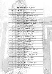
LG Projector RD-JT30 99.J4977.L31 NO PART NO DESCRIPTION 1 35.80J49.091 LENS ROD 6.1X4.4X40 JT30 2 55.J4906.001 PCBA CHIP/BD LG JT30 3 60.J4911.001 ASSY FOLD MIRROR MODULE JT30 4 35.81J49.001 Glass front UVAR JT30 PROT 5 55.J4922.001 PCBA SENSOR/BD LG JT30 6 65.J4905.011 COLOR DRUM 35MM 90DEG JT30 7 65.J4901.011....J4906.001 ASSY REAR COVER JT30 30 60.J4907.001 ASSY LOWER CASE JT30 31 60.J4908.001 ASSY LAMP DOOR JT30 32 23.10095.001 FAN 12V 45*45*10 AD4512HB-G76 33 42.06639.001 BAG PE 450*310*0.04 5535 34 44.J0502.181 CTN 415X325X255 LG JT30 35 47.J4908.001 CSN...
LG Projector RD-JT30 99.J4977.L31 NO PART NO DESCRIPTION 1 35.80J49.091 LENS ROD 6.1X4.4X40 JT30 2 55.J4906.001 PCBA CHIP/BD LG JT30 3 60.J4911.001 ASSY FOLD MIRROR MODULE JT30 4 35.81J49.001 Glass front UVAR JT30 PROT 5 55.J4922.001 PCBA SENSOR/BD LG JT30 6 65.J4905.011 COLOR DRUM 35MM 90DEG JT30 7 65.J4901.011....J4906.001 ASSY REAR COVER JT30 30 60.J4907.001 ASSY LOWER CASE JT30 31 60.J4908.001 ASSY LAMP DOOR JT30 32 23.10095.001 FAN 12V 45*45*10 AD4512HB-G76 33 42.06639.001 BAG PE 450*310*0.04 5535 34 44.J0502.181 CTN 415X325X255 LG JT30 35 47.J4908.001 CSN...

Service Manual
Page 134
Data enable signal output to DMD BD, provided as an indicator that the Lamp is ON or OFF LED1, LED2 - VHS - V-port Even/Odd frame indicator . RESETZ - Memory clock to de-interlace FLI2200. Data clock to CPU as RESETZ ...
Data enable signal output to DMD BD, provided as an indicator that the Lamp is ON or OFF LED1, LED2 - VHS - V-port Even/Odd frame indicator . RESETZ - Memory clock to de-interlace FLI2200. Data clock to CPU as RESETZ ...

Service Manual
Page 136
... will activate. Block Diagram Line EMI Input filter Bridge Rectifier 4.. JT31 Lamp on indication for DDP1000 Lamp on Sequence Signal Voltage Change Description PWRGOOD Low High After the power key pressed 3 second continuously, the POWERON signal will begin initialization. JT31 Normal Lamp off Sequence Signal RESETZ LAMPEN LAMPLIT Voltage Change Description High Low...
... will activate. Block Diagram Line EMI Input filter Bridge Rectifier 4.. JT31 Lamp on indication for DDP1000 Lamp on Sequence Signal Voltage Change Description PWRGOOD Low High After the power key pressed 3 second continuously, the POWERON signal will begin initialization. JT31 Normal Lamp off Sequence Signal RESETZ LAMPEN LAMPLIT Voltage Change Description High Low...

Service Manual
Page 145
...) - The variance of pattern generator : Timing : 480P(H:31.54 KHz,V:60.08 Hz) pattern : black 5. Set user OSD values to default. 9. Black coordinate spec: Osram lamp Oshio lamp x0 0.281 0.01 0.313 0.01 y0 0.311 0.01 0.329 0.01 2. Lux meter ( CL-100) Procedure: (a). 4.HDTV Color Adjustment Procedure Equipment: -
...) - The variance of pattern generator : Timing : 480P(H:31.54 KHz,V:60.08 Hz) pattern : black 5. Set user OSD values to default. 9. Black coordinate spec: Osram lamp Oshio lamp x0 0.281 0.01 0.313 0.01 y0 0.311 0.01 0.329 0.01 2. Lux meter ( CL-100) Procedure: (a). 4.HDTV Color Adjustment Procedure Equipment: -

