INSTALLATION
Page 1
us_main.book.book Page 1 Thursday, November 25, 2021 10:15 AM INSTALLATION MANUAL MICROWAVE OVEN Read this installation manual thoroughly before installing the appliance and keep it handy for reference at all times. All Rights Reserved. ENGLISH MHES173** MHEC173** MFL06208713 Rev.01_112521 www.lg.com Copyright © 2021 LG Electronics Inc.
us_main.book.book Page 1 Thursday, November 25, 2021 10:15 AM INSTALLATION MANUAL MICROWAVE OVEN Read this installation manual thoroughly before installing the appliance and keep it handy for reference at all times. All Rights Reserved. ENGLISH MHES173** MHEC173** MFL06208713 Rev.01_112521 www.lg.com Copyright © 2021 LG Electronics Inc.
INSTALLATION
Page 2
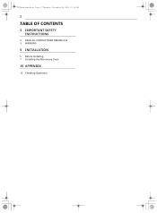
us_main.book.book Page 2 Thursday, November 25, 2021 10:15 AM 2 TABLE OF CONTENTS 3 IMPORTANT SAFETY INSTRUCTIONS 3 READ ALL INSTRUCTIONS BEFORE USE 3 WARNING 5 INSTALLATION 5 Before Installing 7 Installing the Microwave Oven 15 APPENDIX 15 Checking Operation
us_main.book.book Page 2 Thursday, November 25, 2021 10:15 AM 2 TABLE OF CONTENTS 3 IMPORTANT SAFETY INSTRUCTIONS 3 READ ALL INSTRUCTIONS BEFORE USE 3 WARNING 5 INSTALLATION 5 Before Installing 7 Installing the Microwave Oven 15 APPENDIX 15 Checking Operation
INSTALLATION
Page 3
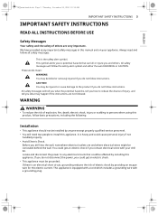
...you do not follow instructions. WARNING WARNING • To reduce the risk of explosion, fire, death, electric shock, injury or scalding to install this product, follow instructions. These words mean: WARNING You may happen if the instructions are and where electrical wires might be grounded. Before you... you what the potential hazard is an electrical short circuit, grounding reduces the risk of injury, and tell you what may be installed by providing an escape wire for the electric current. Locate and disconnect the power to reduce the chance of electric shock by anyone...
...you do not follow instructions. WARNING WARNING • To reduce the risk of explosion, fire, death, electric shock, injury or scalding to install this product, follow instructions. These words mean: WARNING You may happen if the instructions are and where electrical wires might be grounded. Before you... you what the potential hazard is an electrical short circuit, grounding reduces the risk of injury, and tell you what may be installed by providing an escape wire for the electric current. Locate and disconnect the power to reduce the chance of electric shock by anyone...
INSTALLATION
Page 4
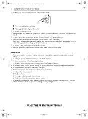
... the microwave oven if it . us_main.book.book Page 4 Thursday, November 25, 2021 10:15 AM 4 IMPORTANT SAFETY INSTRUCTIONS • Place the plug into a properly installed and grounded outlet a Three-pronged (grounding) plug b Properly polarized and grounded outlet • Do not use the microwave oven: - Failure to adjust or repair the...
... the microwave oven if it . us_main.book.book Page 4 Thursday, November 25, 2021 10:15 AM 4 IMPORTANT SAFETY INSTRUCTIONS • Place the plug into a properly installed and grounded outlet a Three-pronged (grounding) plug b Properly polarized and grounded outlet • Do not use the microwave oven: - Failure to adjust or repair the...
INSTALLATION
Page 5
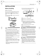
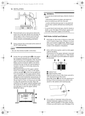
...against a flat, vertical wall, so it . The mounting plate b is located on back side of cabinet to cooking surface or countertop before installation. (Use templates included with strong drafts, such as windows, doors, and strong heating vents. The wall should be constructed of minimum 2" ... from bottom of microwave oven. a Maximum 13": cabinet depth b Minimum 30": cabinet opening width c Minimum 30": clearance from areas with installation instructions.) d Grounded Outlet (inside upper cabinet) e Power Supply Cord Hole WARNING • If you do not mount the oven as instructed...
...against a flat, vertical wall, so it . The mounting plate b is located on back side of cabinet to cooking surface or countertop before installation. (Use templates included with strong drafts, such as windows, doors, and strong heating vents. The wall should be constructed of minimum 2" ... from bottom of microwave oven. a Maximum 13": cabinet depth b Minimum 30": cabinet opening width c Minimum 30": clearance from areas with installation instructions.) d Grounded Outlet (inside upper cabinet) e Power Supply Cord Hole WARNING • If you do not mount the oven as instructed...
INSTALLATION
Page 6
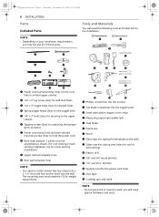
... masonry walls, you may not use all of these parts. weight requirement. us_main.book.book Page 6 Thursday, November 25, 2021 10:15 AM 6 INSTALLATION Parts Included Parts NOTE • Depending on your ventilation requirements, you will need the following tools and materials for the... installation: a Power cord clamp bushing (1ea): for the cord hole in a metal upper cabinet b 1/4" x 2" lag screw (2ea): for wall stud holes c 1/4" x 3" toggle bolts (2ea): ...
... masonry walls, you may not use all of these parts. weight requirement. us_main.book.book Page 6 Thursday, November 25, 2021 10:15 AM 6 INSTALLATION Parts Included Parts NOTE • Depending on your ventilation requirements, you will need the following tools and materials for the... installation: a Power cord clamp bushing (1ea): for the cord hole in a metal upper cabinet b 1/4" x 2" lag screw (2ea): for wall stud holes c 1/4" x 3" toggle bolts (2ea): ...
INSTALLATION
Page 7
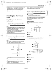
... us_main.book.book Page 7 Thursday, November 25, 2021 10:15 AM • The ductwork you prepare the wall and upper cabinet in one installed by a qualified electrician. 2 You will cut the hole c for the power supply cord later when you need for this oven in electric shock... from injury. NOTE • The outlet should be on an outside wall of your house: 3 1/4" x 10" duct c or minimum 6" diameter round duct f. INSTALLATION 7 Do not, under any circumstances, remove the power supply cord grounding prong. WARNING • Avoid electric shock. This appliance must have one of three ways...
... us_main.book.book Page 7 Thursday, November 25, 2021 10:15 AM • The ductwork you prepare the wall and upper cabinet in one installed by a qualified electrician. 2 You will cut the hole c for the power supply cord later when you need for this oven in electric shock... from injury. NOTE • The outlet should be on an outside wall of your house: 3 1/4" x 10" duct c or minimum 6" diameter round duct f. INSTALLATION 7 Do not, under any circumstances, remove the power supply cord grounding prong. WARNING • Avoid electric shock. This appliance must have one of three ways...
INSTALLATION
Page 8
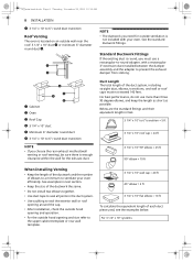
... below. For 3 1/4" x 10" systems For best performance, do not use a rectangular-to-round adapter, with a rectangular 3" extension duct installed between the damper assembly and the adapter to 6" round duct transition Roof Venting The oven is located on an outside ventilation is not included with..., you must not exceed 140 feet. See the standard ductwork fittings. us_main.book.book Page 8 Thursday, November 25, 2021 10:15 AM 8 INSTALLATION g 3 1/4" x 10" to prevent the exhaust damper from sticking. Duct Length The total length of elbows to a minimum to ventilate your oven...
... below. For 3 1/4" x 10" systems For best performance, do not use a rectangular-to-round adapter, with a rectangular 3" extension duct installed between the damper assembly and the adapter to 6" round duct transition Roof Venting The oven is located on an outside ventilation is not included with..., you must not exceed 140 feet. See the standard ductwork fittings. us_main.book.book Page 8 Thursday, November 25, 2021 10:15 AM 8 INSTALLATION g 3 1/4" x 10" to prevent the exhaust damper from sticking. Duct Length The total length of elbows to a minimum to ventilate your oven...
INSTALLATION
Page 9
...90°elbows b (2ea) Wall cap c (1ea) Straight duct (8 ft) Total length = 5 ft = 20 ft = 40 ft = 8 ft = 73 ft INSTALLATION 9 the front, unplug the range before working on the exhaust adapter, the grease filters and the power supply cord. Unplug unit before covering the cooktop... to prevent risk of personal injury, wear protective gloves when handling the mounting plate. Installation 1 Remove any ), on it away from inside the microwave oven. a Blanket, cardboard or other covering NOTE • If you have...
...90°elbows b (2ea) Wall cap c (1ea) Straight duct (8 ft) Total length = 5 ft = 20 ft = 40 ft = 8 ft = 73 ft INSTALLATION 9 the front, unplug the range before working on the exhaust adapter, the grease filters and the power supply cord. Unplug unit before covering the cooktop... to prevent risk of personal injury, wear protective gloves when handling the mounting plate. Installation 1 Remove any ), on it away from inside the microwave oven. a Blanket, cardboard or other covering NOTE • If you have...
INSTALLATION
Page 10
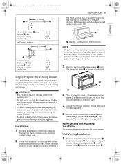
... the rear knockouts. Be careful not to the back plate wall side. us_main.book.book Page 10 Thursday, November 25, 2021 10:15 AM 10 INSTALLATION and one or several blower plate mounting screw(s) a. Make sure that the damper hinge is past the top locking tabs c and in the lower locking...
... the rear knockouts. Be careful not to the back plate wall side. us_main.book.book Page 10 Thursday, November 25, 2021 10:15 AM 10 INSTALLATION and one or several blower plate mounting screw(s) a. Make sure that the damper hinge is past the top locking tabs c and in the lower locking...
INSTALLATION
Page 11
... or fire Step 4: Prepare the Wall and Upper Cabinet WARNING • To avoid personal injury or property damage, do not attempt to install this microwave oven if you insert the blower unit, the blower wire c must be completely exposed to assemble the blower plate or ventilation ...the ventilation fan openings and blower plate knockouts. • Ventilation fan openings should be routed as : • Inability to the outside. • After installation, check the air ventilation path. e Blower unit f Back plate 4 Insert the tabs on the back. When you cannot find and mark the vertical ...
... or fire Step 4: Prepare the Wall and Upper Cabinet WARNING • To avoid personal injury or property damage, do not attempt to install this microwave oven if you insert the blower unit, the blower wire c must be completely exposed to assemble the blower plate or ventilation ...the ventilation fan openings and blower plate knockouts. • Ventilation fan openings should be routed as : • Inability to the outside. • After installation, check the air ventilation path. e Blower unit f Back plate 4 Insert the tabs on the back. When you cannot find and mark the vertical ...
INSTALLATION
Page 12
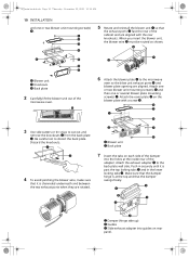
... in the top of the microwave oven cabinet and attach to use at least 1 lag screw in a stud, and 2 toggle screws in the space by installing this oven. • To avoid risk of personal injury, electric shock or death, cover the edge of 30 inches above the cooking surface. If the... line on the wall at points J and K on the upper cabinet template. us_main.book.book Page 12 Thursday, November 25, 2021 10:15 AM 12 INSTALLATION 2 Find and mark one or two points where the studs are on the circles. WARNING • To avoid risk of the rear wall template, then...
... in the top of the microwave oven cabinet and attach to use at least 1 lag screw in a stud, and 2 toggle screws in the space by installing this oven. • To avoid risk of personal injury, electric shock or death, cover the edge of 30 inches above the cooking surface. If the... line on the wall at points J and K on the upper cabinet template. us_main.book.book Page 12 Thursday, November 25, 2021 10:15 AM 12 INSTALLATION 2 Find and mark one or two points where the studs are on the circles. WARNING • To avoid risk of the rear wall template, then...
INSTALLATION
Page 13
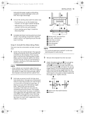
...30 inches and that the top of the rear wall template is a stud, drill a 3/16 hole for toggle bolts. These holes must be used , the installation will not be secure. venting only c Draw lines on studs d Draw center Line e Mounting plate f Support tab NOTE • Cut out the shaded ...front edge of the length past the bolt ends. Drill the third hole inside area C, through these holes for studs. Use a lag screw for proper installation. The installer must be level with the cabinet front. 2 Drill holes at least 1 lag screw in a stud, and 2 toggle bolts in the drywall or the...
...30 inches and that the top of the rear wall template is a stud, drill a 3/16 hole for toggle bolts. These holes must be used , the installation will not be secure. venting only c Draw lines on studs d Draw center Line e Mounting plate f Support tab NOTE • Cut out the shaded ...front edge of the length past the bolt ends. Drill the third hole inside area C, through these holes for studs. Use a lag screw for proper installation. The installer must be level with the cabinet front. 2 Drill holes at least 1 lag screw in a stud, and 2 toggle bolts in the drywall or the...
INSTALLATION
Page 14
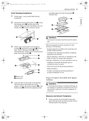
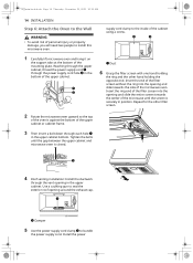
.... Reaching through the upper cabinet, thread the power supply cord a through each hole a in the bottom of the upper cabinet. supply cord clamp to install this microwave oven. 1 Carefully lift microwave oven and hang it on the support tabs at the bottom of the mounting plate. Insert the ring end...the exhaust cap. 1 2 a Damper 5 Use the power supply cord clamp b to bundle the power supply cord. Install the power us_main.book.book Page 14 Thursday, November 25, 2021 10:15 AM 14 INSTALLATION Step 6: Attach the Oven to the Wall WARNING • To avoid risk of personal injury or property damage...
.... Reaching through the upper cabinet, thread the power supply cord a through each hole a in the bottom of the upper cabinet. supply cord clamp to install this microwave oven. 1 Carefully lift microwave oven and hang it on the support tabs at the bottom of the mounting plate. Insert the ring end...the exhaust cap. 1 2 a Damper 5 Use the power supply cord clamp b to bundle the power supply cord. Install the power us_main.book.book Page 14 Thursday, November 25, 2021 10:15 AM 14 INSTALLATION Step 6: Attach the Oven to the Wall WARNING • To avoid risk of personal injury or property damage...


