
Owners Manual
Page 1
LED LCD MONITOR TV MODELS M2080D M2380DF M2280D M2780DF M2380D M2780D www.lg.com ENGLISH OWNER'S MANUAL LED LCD MONITOR TV Please read this manual carefully before operating your set and retain it for future reference.
LED LCD MONITOR TV MODELS M2080D M2380DF M2280D M2780DF M2380D M2780D www.lg.com ENGLISH OWNER'S MANUAL LED LCD MONITOR TV Please read this manual carefully before operating your set and retain it for future reference.

Owners Manual
Page 2
...M2280D/M2380D/M2780D 10 WALL MOUNT: HORIZONTAL INSTALLATION.11 SWIVEL STAND(Only M2780D / M2780DF)....12 DESKTOP PEDESTAL INSTALLATION 12 POSITIONING YOUR DISPLAY 13 LOCATION 13 KENSINGTON SECURITY SYSTEM 14 REMOTE CONTROL KEY FUNCTIONS 33 TURNING ON THE TV 35 CHANNEL SELECTION 35 VOLUME ADJUSTMENT 35 INITIAL SETTING... SUPPORTED DISPLAY RESOLUTIONS 31 ASPECT RATIO SELECTION 46 PICTURE WIZARD 48 ꕫ ENERGY SAVING 49 PRESET PICTURE SETTINGS(PICTURE MODE)... 50 MANUAL PICTURE ADJUSTMENT-USER MODE......51 PICTURE IMPROVEMENT TECHNOLOGY........ 52 EXPERT PICTURE CONTROL 53 ...
...M2280D/M2380D/M2780D 10 WALL MOUNT: HORIZONTAL INSTALLATION.11 SWIVEL STAND(Only M2780D / M2780DF)....12 DESKTOP PEDESTAL INSTALLATION 12 POSITIONING YOUR DISPLAY 13 LOCATION 13 KENSINGTON SECURITY SYSTEM 14 REMOTE CONTROL KEY FUNCTIONS 33 TURNING ON THE TV 35 CHANNEL SELECTION 35 VOLUME ADJUSTMENT 35 INITIAL SETTING... SUPPORTED DISPLAY RESOLUTIONS 31 ASPECT RATIO SELECTION 46 PICTURE WIZARD 48 ꕫ ENERGY SAVING 49 PRESET PICTURE SETTINGS(PICTURE MODE)... 50 MANUAL PICTURE ADJUSTMENT-USER MODE......51 PICTURE IMPROVEMENT TECHNOLOGY........ 52 EXPERT PICTURE CONTROL 53 ...

Owners Manual
Page 3
... AUDIO RESET 66 TV SPEAKERS ON/OFF SETUP 67 STEREO/SAP BROADCAST SETUP 68 TIME SETTING CLOCK SETUP Auto Clock Setup 69 Manual Clock Setup 70 AUTO ON/OFF TIME SETTING 71 SLEEP TIMER SETTING 72 OPTIONAL SETTINGS ON-SCREEN MENUS LANGUAGE SELECTION....73 AUDIO LANGUAGE 74 INPUT LABEL 75 KEY LOCK 76 CAPTION...
... AUDIO RESET 66 TV SPEAKERS ON/OFF SETUP 67 STEREO/SAP BROADCAST SETUP 68 TIME SETTING CLOCK SETUP Auto Clock Setup 69 Manual Clock Setup 70 AUTO ON/OFF TIME SETTING 71 SLEEP TIMER SETTING 72 OPTIONAL SETTINGS ON-SCREEN MENUS LANGUAGE SELECTION....73 AUDIO LANGUAGE 74 INPUT LABEL 75 KEY LOCK 76 CAPTION...

Owners Manual
Page 4
The image shown may be somewhat different from your Monitor set is a simplified representation of the front panel. M2080D / M2280D M2380D / M2780D M2380DF / M2780DF PREPARATION 1 1 2 3 45 6 7 89 1 IR RECEIVER (remote control signal receiver) 2 SPEAKER (WOOFER) 3 INPUT BUTTON 4 MENU BUTTON 5 ENTER BUTTON 6 VOLUME BUTTON 7 CHANNEL BUTTON 8 POWER BUTTON 9 POWER INDICATOR Illuminates blue when the set . PREPARATION FRONT PANEL INFORMATION ■■ This is switched on. Note: You can adjust the power indicator in the OPTION menu. 4
The image shown may be somewhat different from your Monitor set is a simplified representation of the front panel. M2080D / M2280D M2380D / M2780D M2380DF / M2780DF PREPARATION 1 1 2 3 45 6 7 89 1 IR RECEIVER (remote control signal receiver) 2 SPEAKER (WOOFER) 3 INPUT BUTTON 4 MENU BUTTON 5 ENTER BUTTON 6 VOLUME BUTTON 7 CHANNEL BUTTON 8 POWER BUTTON 9 POWER INDICATOR Illuminates blue when the set . PREPARATION FRONT PANEL INFORMATION ■■ This is switched on. Note: You can adjust the power indicator in the OPTION menu. 4

Owners Manual
Page 5
... socket. 6 RS-232C IN (CONTROL & SERVICE) PORT Connect to the RS-232C port on a PC. The image shown may be somewhat different from your Monitor set. M2080D / M2280D M2380D / M2780D M2380DF / M2780DF 1 2 3 45 6 78 9 10 11 1 DC ADAPTER PORT Connect to the power jack. 2 HDMI INPUT Connect an HDMI signal to HDMI...
... socket. 6 RS-232C IN (CONTROL & SERVICE) PORT Connect to the RS-232C port on a PC. The image shown may be somewhat different from your Monitor set. M2080D / M2280D M2380D / M2780D M2380DF / M2780DF 1 2 3 45 6 78 9 10 11 1 DC ADAPTER PORT Connect to the power jack. 2 HDMI INPUT Connect an HDMI signal to HDMI...

Owners Manual
Page 6
PREPARATION PREPARATION STAND INSTALLATION M2080D/M2280D/M2380D/M2780D ■■ The image shown may be somewhat different from damage. 2 Insert the Stand Base into the product. Stand Base 3 Use a Coin on a cushioned surface that will protect the Monitor set and its screen from your Monitor set. 1 Carefully place the product screen side down on the bottom of the stand base and turn the screw clockwise to tighten. Coin 6
PREPARATION PREPARATION STAND INSTALLATION M2080D/M2280D/M2380D/M2780D ■■ The image shown may be somewhat different from damage. 2 Insert the Stand Base into the product. Stand Base 3 Use a Coin on a cushioned surface that will protect the Monitor set and its screen from your Monitor set. 1 Carefully place the product screen side down on the bottom of the stand base and turn the screw clockwise to tighten. Coin 6

Owners Manual
Page 7
Coin 7 Stand Base 3 Use a Coin on a cushioned surface that will protect the Monitor set . PREPARATION STAND INSTALLATION ■■ The image shown may be somewhat different from your Monitor set and its screen from damage. 2 Insert the Stand Base into the product. M2380DF/M2780DF 1 Carefully place the product screen side down on the bottom of the stand base and turn the screw clockwise to tighten.
Coin 7 Stand Base 3 Use a Coin on a cushioned surface that will protect the Monitor set . PREPARATION STAND INSTALLATION ■■ The image shown may be somewhat different from your Monitor set and its screen from damage. 2 Insert the Stand Base into the product. M2380DF/M2780DF 1 Carefully place the product screen side down on the bottom of the stand base and turn the screw clockwise to tighten.
Owners Manual
Page 8
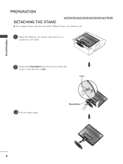
Stand Base 8 Coin 3 Pull the stand base. PREPARATION PREPARATION M2080D/M2280D/M2380D/M2780D DETACHING THE STAND ■■ The image shown may be somewhat different from your Monitor set. 1 Place the Monitor set screen side down on a cushion or soft cloth. 2 Detach the Stand Base from the set by turning the screw to the left with a Coin.
Stand Base 8 Coin 3 Pull the stand base. PREPARATION PREPARATION M2080D/M2280D/M2380D/M2780D DETACHING THE STAND ■■ The image shown may be somewhat different from your Monitor set. 1 Place the Monitor set screen side down on a cushion or soft cloth. 2 Detach the Stand Base from the set by turning the screw to the left with a Coin.

Owners Manual
Page 9
Stand Base 9 PREPARATION DETACHING THE STAND ■■ The image shown may be somewhat different from the set . Coin 3 Pull the stand base. M2380DF/M2780DF 1 Place the Monitor set screen side down on a cushion or soft cloth. 2 Detach the Stand Base from your Monitor set by turning the screw to the left with a Coin.
Stand Base 9 PREPARATION DETACHING THE STAND ■■ The image shown may be somewhat different from the set . Coin 3 Pull the stand base. M2380DF/M2780DF 1 Place the Monitor set screen side down on a cushion or soft cloth. 2 Detach the Stand Base from your Monitor set by turning the screw to the left with a Coin.

Owners Manual
Page 10
Assemble the screw 2 points. Remove the screw 2 points. 2. Screw 10 Pull the stand body. 3. PREPARATION PREPARATION DETACHING THE STAND BODY (Only M2080D/ M2280D/M2380D/M2780D) ■ When using a VESA mount on the monitor set, you may wish to remove the stand body. ■ The image shown may be somewhat different from your Monitor set. 1.
Assemble the screw 2 points. Remove the screw 2 points. 2. Screw 10 Pull the stand body. 3. PREPARATION PREPARATION DETACHING THE STAND BODY (Only M2080D/ M2280D/M2380D/M2780D) ■ When using a VESA mount on the monitor set, you may wish to remove the stand body. ■ The image shown may be somewhat different from your Monitor set. 1.

Owners Manual
Page 11
... optional Tilt Wall Mounting Bracket Installation and Setup Guide. 10 cm 10 cm 10 cm 10 cm 10 cm If you install the Monitor set . LG is not responsible for any damage resulting from the wall. "VESA compatible" refers to use a VESA standard wall mount pad and screws. ... Screw Mounting Interface Dimensions > Model VESA ( A x B) Wall mount bracket(optional) M2080D M2280D M2380D M2380DF 75 x 75 RW120 M2780D M2780DF 200 x 100 RW240 Wall Mount Pad 11 When you intend to mount the Monitor set to a wall, attach the wall mounting interface (optional) to the back of 10 cm ...
... optional Tilt Wall Mounting Bracket Installation and Setup Guide. 10 cm 10 cm 10 cm 10 cm 10 cm If you install the Monitor set . LG is not responsible for any damage resulting from the wall. "VESA compatible" refers to use a VESA standard wall mount pad and screws. ... Screw Mounting Interface Dimensions > Model VESA ( A x B) Wall mount bracket(optional) M2080D M2280D M2380D M2380DF 75 x 75 RW120 M2780D M2780DF 200 x 100 RW240 Wall Mount Pad 11 When you intend to mount the Monitor set to a wall, attach the wall mounting interface (optional) to the back of 10 cm ...

Owners Manual
Page 12
M2080D / M2280D M2380D / M2780D 10 cm 10 cm 10 cm 10 cm M2380DF / M2780DF 12 10 cm 10 cm 10 cm 10 cm For proper ventilation, allow a clearance of 10 cm on each side and from the wall. After installing the set, you can adjust the set . M2780D M2780DF PREPARATION... DESKTOP PEDESTAL INSTALLATION ■■ The image shown may be somewhat different from your Monitor set manually to the left or right direction by 179 degrees to suit your Monitor set. PREPARATION SWIVEL STAND(Only M2780D / M2780DF) ■■ The image shown may be somewhat ...
M2080D / M2280D M2380D / M2780D 10 cm 10 cm 10 cm 10 cm M2380DF / M2780DF 12 10 cm 10 cm 10 cm 10 cm For proper ventilation, allow a clearance of 10 cm on each side and from the wall. After installing the set, you can adjust the set . M2780D M2780DF PREPARATION... DESKTOP PEDESTAL INSTALLATION ■■ The image shown may be somewhat different from your Monitor set manually to the left or right direction by 179 degrees to suit your Monitor set. PREPARATION SWIVEL STAND(Only M2780D / M2780DF) ■■ The image shown may be somewhat ...

Owners Manual
Page 13
... placed in various ways for maximum comfort. * Tilt Range -5° 10° -5° 10° PREPARATION M2080D / M2280D / M2380D / M2780D M2380DF / M2780DF LOCATION Position your set. WARNING ■ When adjusting the angle of the screen, do not put your finger(s). Do not cover the ventilation openings on... cover. POSITIONING YOUR DISPLAY ■ The image shown may be taken not to expose the set to allow a free flow of air. Care should be somewhat different from your set so that no bright light or sunlight falls directly onto the screen. You can hurt your finger...
... placed in various ways for maximum comfort. * Tilt Range -5° 10° -5° 10° PREPARATION M2080D / M2280D / M2380D / M2780D M2380DF / M2780DF LOCATION Position your set. WARNING ■ When adjusting the angle of the screen, do not put your finger(s). Do not cover the ventilation openings on... cover. POSITIONING YOUR DISPLAY ■ The image shown may be taken not to expose the set to allow a free flow of air. Care should be somewhat different from your set so that no bright light or sunlight falls directly onto the screen. You can hurt your finger...

Owners Manual
Page 15
EXTERNAL EQUIPMENT SETUP ■■ To prevent damage, do not connect the set . EXTERNAL EQUIPMENT SETUP Wall Antenna Socket Outdoor Antenna (VHF, UHF) Multi-family Dwellings/Apartments (Connect to wall antenna socket) RF Coaxial Wire (75 Ω) Single-.... ANTENNA CONNECTION ■■ For optimum picture quality, adjust the antenna's direction. ■■ An antenna cable and converter are not included with the Monitor set to be split for two devices, use an antenna signal splitter. 15
EXTERNAL EQUIPMENT SETUP ■■ To prevent damage, do not connect the set . EXTERNAL EQUIPMENT SETUP Wall Antenna Socket Outdoor Antenna (VHF, UHF) Multi-family Dwellings/Apartments (Connect to wall antenna socket) RF Coaxial Wire (75 Ω) Single-.... ANTENNA CONNECTION ■■ For optimum picture quality, adjust the antenna's direction. ■■ An antenna cable and converter are not included with the Monitor set to be split for two devices, use an antenna signal splitter. 15

Owners Manual
Page 16
...equipment. ■■ The image shown may be somewhat different from your Monitor set -top box.) 4 Select COMPONENT input source using the INPUT button on the digital set-top box. (Refer to the owner's manual for the digital set . HD RECEIVER SETUP Connecting with a Component Cable 1 Connect the video outputs ...(Y, PB, PR) of the digital set-top box to the COMPONENT IN VIDEO jacks on the Monitor set. 2 Connect the audio output of the digital set-top box to the COMPONENT IN AUDIO jacks on the Monitor set. 3 Turn on the remote control. 1 2 ►►HDMI...
...equipment. ■■ The image shown may be somewhat different from your Monitor set -top box.) 4 Select COMPONENT input source using the INPUT button on the digital set-top box. (Refer to the owner's manual for the digital set . HD RECEIVER SETUP Connecting with a Component Cable 1 Connect the video outputs ...(Y, PB, PR) of the digital set-top box to the COMPONENT IN VIDEO jacks on the Monitor set. 2 Connect the audio output of the digital set-top box to the COMPONENT IN AUDIO jacks on the Monitor set. 3 Turn on the remote control. 1 2 ►►HDMI...

Owners Manual
Page 17
NOTE ►►Check that your HDMI cable is a high speed HDMI cable. If the HDMI cables are not high speed, flickering or no screen display can result. 17 EXTERNAL EQUIPMENT SETUP Connecting a Set-top Box with an HDMI Cable 1 Connect the digital set-top box to the HDMI/DVI IN 1 or HDMI/DVI IN 2 jack on the Monitor set. 2 Turn on the digital set-top box. (Refer to the owner's manual for the digital set-top box.) 3 Select HDMI 1 or HDMI 2 input source using the INPUT button on the remote control. 1 !
NOTE ►►Check that your HDMI cable is a high speed HDMI cable. If the HDMI cables are not high speed, flickering or no screen display can result. 17 EXTERNAL EQUIPMENT SETUP Connecting a Set-top Box with an HDMI Cable 1 Connect the digital set-top box to the HDMI/DVI IN 1 or HDMI/DVI IN 2 jack on the Monitor set. 2 Turn on the digital set-top box. (Refer to the owner's manual for the digital set-top box.) 3 Select HDMI 1 or HDMI 2 input source using the INPUT button on the remote control. 1 !

Owners Manual
Page 18
EXTERNAL EQUIPMENT SETUP EXTERNAL EQUIPMENT SETUP Connecting with an HDMI to DVI Cable 1 Connect the digital set-top box to the HDMI/DVI IN 1 or HDMI/DVI IN 2 jack on the Monitor set. 2 Connect the audio output of the digital set-top box to the AUDIO IN (RGB/DVI) jack on the Monitor set. 3 Turn on the digital set-top box. (Refer to the owner's manual for the digital set-top box.) 4 Select HDMI 1 or HDMI 2 using the INPUT on the remote control. 1 2 18
EXTERNAL EQUIPMENT SETUP EXTERNAL EQUIPMENT SETUP Connecting with an HDMI to DVI Cable 1 Connect the digital set-top box to the HDMI/DVI IN 1 or HDMI/DVI IN 2 jack on the Monitor set. 2 Connect the audio output of the digital set-top box to the AUDIO IN (RGB/DVI) jack on the Monitor set. 3 Turn on the digital set-top box. (Refer to the owner's manual for the digital set-top box.) 4 Select HDMI 1 or HDMI 2 using the INPUT on the remote control. 1 2 18
Owners Manual
Page 19
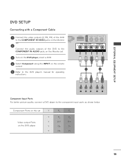
Component Ports on the set . 3 Turn on the DVD player, insert a DVD. 4 Select Component using the INPUT on the DVD player Y PB PR Y B-Y R-Y Y Cb Cr Y Pb Pr 19 EXTERNAL EQUIPMENT ... the video outputs (Y, PB, PR) of the DVD to the COMPONENT IN VIDEO jacks on the Monitor set. 2 Connect the audio outputs of the DVD to the COMPONENT IN AUDIO jacks on the Monitor set Y PB PR Video output Ports on the remote control. 5 Refer to the DVD player's manual for operating...
Component Ports on the set . 3 Turn on the DVD player, insert a DVD. 4 Select Component using the INPUT on the DVD player Y PB PR Y B-Y R-Y Y Cb Cr Y Pb Pr 19 EXTERNAL EQUIPMENT ... the video outputs (Y, PB, PR) of the DVD to the COMPONENT IN VIDEO jacks on the Monitor set. 2 Connect the audio outputs of the DVD to the COMPONENT IN AUDIO jacks on the Monitor set Y PB PR Video output Ports on the remote control. 5 Refer to the DVD player's manual for operating...
Owners Manual
Page 20
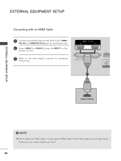
NOTE ►►Check that your HDMI cable is a high speed HDMI cable. If the HDMI cables are not high speed, flickering or no screen display can result. 20 EXTERNAL EQUIPMENT SETUP EXTERNAL EQUIPMENT SETUP Connecting with an HDMI Cable 1 Connect the HDMI output of the DVD to the HDMI/ DVI IN 1 or HDMI/DVI IN 2 jack on the Monitor set. 2 Select HDMI 1 or HDMI 2 using the INPUT on the remote control. 3 Refer to the DVD player's manual for operating instructions. 1 !
NOTE ►►Check that your HDMI cable is a high speed HDMI cable. If the HDMI cables are not high speed, flickering or no screen display can result. 20 EXTERNAL EQUIPMENT SETUP EXTERNAL EQUIPMENT SETUP Connecting with an HDMI Cable 1 Connect the HDMI output of the DVD to the HDMI/ DVI IN 1 or HDMI/DVI IN 2 jack on the Monitor set. 2 Select HDMI 1 or HDMI 2 using the INPUT on the remote control. 3 Refer to the DVD player's manual for operating instructions. 1 !

Owners Manual
Page 21
Connecting with an RF Cable 1 Wall Jack 2 Antenna 1 Connect the ANT OUT socket of the VCR to the ANTENNA/CABLE IN socket on the Monitor set. 2 Connect the antenna cable to the ANT IN socket of the VCR. 3 Press PLAY on the VCR and match the appropriate channel between the VCR and set and the VCR for viewing. 21 EXTERNAL EQUIPMENT SETUP VCR SETUP ■■ To avoid picture noise (interference), allow adequate distance between the set .
Connecting with an RF Cable 1 Wall Jack 2 Antenna 1 Connect the ANT OUT socket of the VCR to the ANTENNA/CABLE IN socket on the Monitor set. 2 Connect the antenna cable to the ANT IN socket of the VCR. 3 Press PLAY on the VCR and match the appropriate channel between the VCR and set and the VCR for viewing. 21 EXTERNAL EQUIPMENT SETUP VCR SETUP ■■ To avoid picture noise (interference), allow adequate distance between the set .


