Owners Manual
Page 1
registered mark. ENERGY STAR® is a U.S. HDTV DIGITAL VIDEO RECORDER / RECEIVER (HD DVR) OWNER'S MANUAL MODEL: LST-3410A Before connecting, operating or adjusting this product, please read this product or product models meets the ENERGY STAR® guidelines for energy efficiency. Call us and we will guide you through your first recording, for free. 1-800-243-0000 As an ENERGY STAR® Partner, LG has determined that this owner's manual carefully and completely.
registered mark. ENERGY STAR® is a U.S. HDTV DIGITAL VIDEO RECORDER / RECEIVER (HD DVR) OWNER'S MANUAL MODEL: LST-3410A Before connecting, operating or adjusting this product, please read this product or product models meets the ENERGY STAR® guidelines for energy efficiency. Call us and we will guide you through your first recording, for free. 1-800-243-0000 As an ENERGY STAR® Partner, LG has determined that this owner's manual carefully and completely.
Owners Manual
Page 4
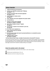
... Indicates hazards likely to cause harm to personal preference or as required by EZ Scan, run EZ Scan again; Indicates tips and hints for HD DVR. Setup Checklist 1. 2. 3. 4. 5. 6. 7. 8. 9. See pages 16 - 22. when the DTV channel is selected.) Set up the TV Guide On Screen™ System.... See page 28. 10. Choose on screen menu language. Use EZ Scan* to antenna and TV/Monitor. Unpack HD DVR and all external video and audio equipment. As a result, some DTV channels may not be found by source. Indicates special operating features of Contents....
... Indicates hazards likely to cause harm to personal preference or as required by EZ Scan, run EZ Scan again; Indicates tips and hints for HD DVR. Setup Checklist 1. 2. 3. 4. 5. 6. 7. 8. 9. See pages 16 - 22. when the DTV channel is selected.) Set up the TV Guide On Screen™ System.... See page 28. 10. Choose on screen menu language. Use EZ Scan* to antenna and TV/Monitor. Unpack HD DVR and all external video and audio equipment. As a result, some DTV channels may not be found by source. Indicates special operating features of Contents....

Owners Manual
Page 5
...Set Password ...38 Block Ch. (Channel) ...39 Movie Rating ...39 TV Rating-Children ...40 TV Rating-General ...41 Aux.Block ...42 DVR Menu Operation ...43-45 TV Guide On Screen™ System ...43 Program List ...44 HDD Format ...45 Recording Quality ...45 Information Displays ...... in LISTINGS...58 VCR Plus+ Recording ...59 Canceling FAVORITES/RECORD...59 Channel Editor ...60 On/Off Setup ...60 INTRODUCTION INSTALLATION Unpacking HD DVR and Accessories/ Connection Overview ...10 Connections ...11-22 Antenna/CATV (Cable Service) Connections...11 Analog TV/Monitor Connections ...12 HD TV/Monitor...
...Set Password ...38 Block Ch. (Channel) ...39 Movie Rating ...39 TV Rating-Children ...40 TV Rating-General ...41 Aux.Block ...42 DVR Menu Operation ...43-45 TV Guide On Screen™ System ...43 Program List ...44 HDD Format ...45 Recording Quality ...45 Information Displays ...... in LISTINGS...58 VCR Plus+ Recording ...59 Canceling FAVORITES/RECORD...59 Channel Editor ...60 On/Off Setup ...60 INTRODUCTION INSTALLATION Unpacking HD DVR and Accessories/ Connection Overview ...10 Connections ...11-22 Antenna/CATV (Cable Service) Connections...11 Analog TV/Monitor Connections ...12 HD TV/Monitor...

Owners Manual
Page 6
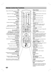
... highlighted MENU option. SELECT If the main menu is displayed, the 1 / 2 buttons control the volume setting and the 3 / 4 buttons select channels. Power Turns the HD DVR on and off. Remote Control Sensor Receives signals from any menu. 6 To stop recording, press the button again.
... highlighted MENU option. SELECT If the main menu is displayed, the 1 / 2 buttons control the volume setting and the 3 / 4 buttons select channels. Power Turns the HD DVR on and off. Remote Control Sensor Receives signals from any menu. 6 To stop recording, press the button again.
Owners Manual
Page 7
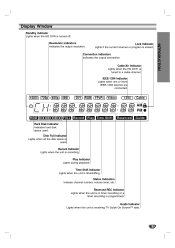
...channel or program is tuned to a cable channel. Resolution indicators Indicates the output resolution. Cable/Air Indicator Lights when the HD DVR is locked. Time Shift Indicator Lights when the unit is programmed. Reserved REC Indicator Lights when the unit is in timer ...recording or a timer recording is timeshifting. Display Window Standby indicator Lights when the HD DVR is used . Play Indicator Lights during playback. Status Indicators Indicate channel number, volume level, etc. INTRODUCTION Connection indicators Indicates the ...
...channel or program is tuned to a cable channel. Resolution indicators Indicates the output resolution. Cable/Air Indicator Lights when the HD DVR is locked. Time Shift Indicator Lights when the unit is programmed. Reserved REC Indicator Lights when the unit is in timer ...recording or a timer recording is timeshifting. Display Window Standby indicator Lights when the HD DVR is used . Play Indicator Lights during playback. Status Indicators Indicate channel number, volume level, etc. INTRODUCTION Connection indicators Indicates the ...
Owners Manual
Page 8
Remote Control Key Functions STB Selects STB (HD DVR) operational mode on and off. MODE Selects operational mode for multiple program channels such as 2-1, 2-2, etc. SIGNAL Shows signal strength of current playback or a repeated ... Moves to the current TV program live TV and marks any menu or removes the progress bar during timeshift and playback. POWER Turns the HD DVR ON and OFF. RATIO Changes the picture aspect ratio. 1394 Shows list of a program during playback or returns to the end point of connected IEEE...
Remote Control Key Functions STB Selects STB (HD DVR) operational mode on and off. MODE Selects operational mode for multiple program channels such as 2-1, 2-2, etc. SIGNAL Shows signal strength of current playback or a repeated ... Moves to the current TV program live TV and marks any menu or removes the progress bar during timeshift and playback. POWER Turns the HD DVR ON and OFF. RATIO Changes the picture aspect ratio. 1394 Shows list of a program during playback or returns to the end point of connected IEEE...
Owners Manual
Page 9
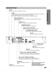
.... Fixed "volume" AUDIO OUT (Left/Right) Connect to IEEE-1394 equipment. Do not touch the inner pins of this audio out on HD DVR. COMPONENT OUTPUT Connect to TV/Monitor with YPbPr inputs. IEEE-1394 Connect to a TV, amplifier, receiver or stereo system. AUTHORIZED SERVICE ONLY Is... purposes. S-VIDEO OUT Connect to TV/Monitor with S-Video input. AUDIO/VIDEO INPUT 1, 2 Connect audio/video output of this audio out on HD DVR. You can adjust the volume of an external source (Audio system, TV/Monitor, VCR, Camcorder). CABLE IN Connect to digital (optical) audio equipment....
.... Fixed "volume" AUDIO OUT (Left/Right) Connect to IEEE-1394 equipment. Do not touch the inner pins of this audio out on HD DVR. COMPONENT OUTPUT Connect to TV/Monitor with YPbPr inputs. IEEE-1394 Connect to a TV, amplifier, receiver or stereo system. AUTHORIZED SERVICE ONLY Is... purposes. S-VIDEO OUT Connect to TV/Monitor with S-Video input. AUDIO/VIDEO INPUT 1, 2 Connect audio/video output of this audio out on HD DVR. You can adjust the volume of an external source (Audio system, TV/Monitor, VCR, Camcorder). CABLE IN Connect to digital (optical) audio equipment....
Owners Manual
Page 10
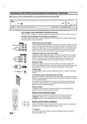
...jacks carry only the picture signals, not the sound. Caution Do not mix old and new batteries. HDTV DIGITAL VIDEO RECORDER / RECEIVER (HD DVR) This HD DVR is used to the left and right audio cables. DE MO PIN TV Guide On Screen System Demo Pin and Tag Demo Pin consists... IR controlled external devices. DVI-HDTV Cable DVI cable is capable of the remote control, and install two batteries (size AA) with the HD DVR are the following accessories. A DVI jack carries only the video signals, not the audio. This disables the retail Demo feature and allows normal Host...
...jacks carry only the picture signals, not the sound. Caution Do not mix old and new batteries. HDTV DIGITAL VIDEO RECORDER / RECEIVER (HD DVR) This HD DVR is used to the left and right audio cables. DE MO PIN TV Guide On Screen System Demo Pin and Tag Demo Pin consists... IR controlled external devices. DVI-HDTV Cable DVI cable is capable of the remote control, and install two batteries (size AA) with the HD DVR are the following accessories. A DVI jack carries only the video signals, not the audio. This disables the retail Demo feature and allows normal Host...

Owners Manual
Page 11
... "HDTV Program Schedule" under normal or weak signal conditions, providing the best reception with a coaxial RF cable. Antenna Cable TV Wall Jack Panel HD DVR Connection Panel 11 Connections Antenna/CATV (Cable Service) Connections Before connecting an antenna and/or cable service The LST-3410A is a high performance, high gain... system intended for your cable TV (CATV) service to Zenith website "WWW.ZENITH.COM" and clicking on the HD DVR with its optimum gain capability. You can find HDTV channels/content information for operation under HDTV.
... "HDTV Program Schedule" under normal or weak signal conditions, providing the best reception with a coaxial RF cable. Antenna Cable TV Wall Jack Panel HD DVR Connection Panel 11 Connections Antenna/CATV (Cable Service) Connections Before connecting an antenna and/or cable service The LST-3410A is a high performance, high gain... system intended for your cable TV (CATV) service to Zenith website "WWW.ZENITH.COM" and clicking on the HD DVR with its optimum gain capability. You can find HDTV channels/content information for operation under HDTV.
Owners Manual
Page 12
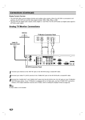
... RCA-type cables. Dolby Digital 5.1 and PCM. the "AUDIO OUT" and "VIDEO OUT" jacks from the HD DVR to Setting the Display Format on the HD DVR using a coaxial RF cable. 2 Connect your TV/Monitor 3 Connect with a coaxial RF cable. If your TV/Monitor is not included. 12 Analog TV/...Monitor Connections Antenna TV/Monitor Connection Panel ANTENNA INPUT S-VIDEO INPUT VIDEO INPUT AUDIO INPUT L R Cable TV Wall Jack Panel OR HD DVR Connection Panel 1 Connect your Antenna to the "ANT IN" jack on page 23). Connections (Continued) Display Formats Overview • The HD...
... RCA-type cables. Dolby Digital 5.1 and PCM. the "AUDIO OUT" and "VIDEO OUT" jacks from the HD DVR to Setting the Display Format on the HD DVR using a coaxial RF cable. 2 Connect your TV/Monitor 3 Connect with a coaxial RF cable. If your TV/Monitor is not included. 12 Analog TV/...Monitor Connections Antenna TV/Monitor Connection Panel ANTENNA INPUT S-VIDEO INPUT VIDEO INPUT AUDIO INPUT L R Cable TV Wall Jack Panel OR HD DVR Connection Panel 1 Connect your Antenna to the "ANT IN" jack on page 23). Connections (Continued) Display Formats Overview • The HD...
Owners Manual
Page 13
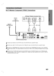
... TV/Monitor 3 Connect with a coaxial RF cable. If your TV/Monitor is equipped with 4 Connect RCA-type cables. the "COMPONENT OUT" jacks from the HD DVR to the L/R "AUDIO IN" jacks on your TV/Monitor with a "Digital Audio Input (Optical)" jack, connect to "DIGITAL AUDIO (OPTICAL OUT)" jack. 13 Connections... INPUT AUDIO INPUT COMPONENT VIDEO INPUT OPTICAL R L Y Pb Pr DIGITAL INPUT Cable TV Wall Jack Panel OR HD DVR Connection Panel 1 Connect your Antenna to the "ANT IN" jack on the HD DVR with a coaxial RF cable. 2 Connect your cable TV (CATV) service to the "CABLE IN" jack on the...
... TV/Monitor 3 Connect with a coaxial RF cable. If your TV/Monitor is equipped with 4 Connect RCA-type cables. the "COMPONENT OUT" jacks from the HD DVR to the L/R "AUDIO IN" jacks on your TV/Monitor with a "Digital Audio Input (Optical)" jack, connect to "DIGITAL AUDIO (OPTICAL OUT)" jack. 13 Connections... INPUT AUDIO INPUT COMPONENT VIDEO INPUT OPTICAL R L Y Pb Pr DIGITAL INPUT Cable TV Wall Jack Panel OR HD DVR Connection Panel 1 Connect your Antenna to the "ANT IN" jack on the HD DVR with a coaxial RF cable. 2 Connect your cable TV (CATV) service to the "CABLE IN" jack on the...

Owners Manual
Page 14
a RGB (D-SUB type) cable, connect the "RGB OUT" jack from the HD DVR to the L/R "AUDIO IN" jacks on your TV/Monitor with 4 Connect standard RCA-type ...S-VIDEO INPUT AUDIO INPUT VIDEO INPUT RGB INPUT R L Cable TV Wall Jack Panel HD DVR Connection Panel 1 Connect your Antenna to the "ANT IN" jack on the HD DVR with a coaxial RF cable. 2 Connect your cable TV (CATV) service to the ..."CABLE IN" jack on page 23). the L/R "AUDIO OUT" jacks from the HD DVR to the "RGB IN" jack on your 3 Using TV/Monitor. (The Output Selection must be set to RGB, refer to ...
a RGB (D-SUB type) cable, connect the "RGB OUT" jack from the HD DVR to the L/R "AUDIO IN" jacks on your TV/Monitor with 4 Connect standard RCA-type ...S-VIDEO INPUT AUDIO INPUT VIDEO INPUT RGB INPUT R L Cable TV Wall Jack Panel HD DVR Connection Panel 1 Connect your Antenna to the "ANT IN" jack on the HD DVR with a coaxial RF cable. 2 Connect your cable TV (CATV) service to the ..."CABLE IN" jack on page 23). the L/R "AUDIO OUT" jacks from the HD DVR to the "RGB IN" jack on your 3 Using TV/Monitor. (The Output Selection must be set to RGB, refer to ...
Owners Manual
Page 15
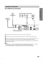
... Connection Panel ANTENNA INPUT S-VIDEO INPUT VIDEO INPUT AUDIO INPUT DVI-HDTV INPUT L R Cable TV Wall Jack Panel HD DVR Connection Panel 1 Connect your Antenna to the "ANT IN" jack on the HD DVR with a coaxial RF cable. 2 Connect your cable TV (CATV) service to the "CABLE IN" jack on your TV... Setting the Display Format on page 23.) the L/R "AUDIO OUT" jacks from the HD DVR to the "DVI IN" jack on the HD DVR with EIA-861 and HDCP specifications. the "DVI OUT" jack from the HD DVR to find out if the TV or monitor's DVI input is compliant with a coaxial RF...
... Connection Panel ANTENNA INPUT S-VIDEO INPUT VIDEO INPUT AUDIO INPUT DVI-HDTV INPUT L R Cable TV Wall Jack Panel HD DVR Connection Panel 1 Connect your Antenna to the "ANT IN" jack on the HD DVR with a coaxial RF cable. 2 Connect your cable TV (CATV) service to the "CABLE IN" jack on your TV... Setting the Display Format on page 23.) the L/R "AUDIO OUT" jacks from the HD DVR to the "DVI IN" jack on the HD DVR with EIA-861 and HDCP specifications. the "DVI OUT" jack from the HD DVR to find out if the TV or monitor's DVI input is compliant with a coaxial RF...

Owners Manual
Page 16
Refer to VIDEO. Connections (Continued) VCR Connections VCR Connection Panel AUDIO INPUT VIDEO INPUT R L HD DVR Connection Panel Connect the L/R "AUDIO OUT" jacks and "VIDEO OUT" jack from the HD DVR to the "A/V in" jacks on your VCR with standard RCA-type cables. (If your VCR is equipped with an S-Video jack..., you can use the "S-VIDEO" connection with an "S-Video" cable instead.) Cautions • To record the HD DVR's contents to VCR, the Output Selection must be set to Setting the Display Format on page 23. • The VCR will record an on screen...
Refer to VIDEO. Connections (Continued) VCR Connections VCR Connection Panel AUDIO INPUT VIDEO INPUT R L HD DVR Connection Panel Connect the L/R "AUDIO OUT" jacks and "VIDEO OUT" jack from the HD DVR to the "A/V in" jacks on your VCR with standard RCA-type cables. (If your VCR is equipped with an S-Video jack..., you can use the "S-VIDEO" connection with an "S-Video" cable instead.) Cautions • To record the HD DVR's contents to VCR, the Output Selection must be set to Setting the Display Format on page 23. • The VCR will record an on screen...
Owners Manual
Page 17
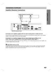
... audio cable. Connections (Continued) Amplifier (Receiver) Connections INSTALLATION Amplifier (Receiver) Connection Panel R L OPTICAL DIGITAL INPUT AUDIO INPUT OR HD DVR Connection Panel Connection for an Audio/ Video receiver equipped with the audio cables supplied. Connection for an amplifier equipped with two channel digital stereo ...for an amplifier equipped with two channel analog stereo or Dolby Surround Connect the left and right AUDIO OUT jacks from the HD DVR to the audio left and right in jacks on your amplifier, receiver, or stereo system, with a multi-channel decoder (Dolby...
... audio cable. Connections (Continued) Amplifier (Receiver) Connections INSTALLATION Amplifier (Receiver) Connection Panel R L OPTICAL DIGITAL INPUT AUDIO INPUT OR HD DVR Connection Panel Connection for an Audio/ Video receiver equipped with the audio cables supplied. Connection for an amplifier equipped with two channel digital stereo ...for an amplifier equipped with two channel analog stereo or Dolby Surround Connect the left and right AUDIO OUT jacks from the HD DVR to the audio left and right in jacks on your amplifier, receiver, or stereo system, with a multi-channel decoder (Dolby...
Owners Manual
Page 18
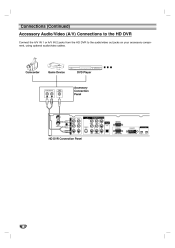
Connections (Continued) Accessory Audio/Video (A/V) Connections to the HD DVR Connect the A/V IN 1 or A/V IN 2 jacks from the HD DVR to the audio/video out jacks on your accessory component, using optional audio/video cables. Camcorder Game Device DVD Player AUDIO OUTPUT VIDEO OUTPUT Accessory Connection Panel L R HD DVR Connection Panel 18
Connections (Continued) Accessory Audio/Video (A/V) Connections to the HD DVR Connect the A/V IN 1 or A/V IN 2 jacks from the HD DVR to the audio/video out jacks on your accessory component, using optional audio/video cables. Camcorder Game Device DVD Player AUDIO OUTPUT VIDEO OUTPUT Accessory Connection Panel L R HD DVR Connection Panel 18

Owners Manual
Page 19
...cable with a coaxial RF cable. Cable TV Wall Jack Panel Cable Box Connection Panel CABLE INPUT LOOP OUT VIDEO OUTPUT AUDIO OUTPUT INSTALLATION Antenna L R HD DVR Connection Panel Cable Box Controller Cable Box (front view) IR Sensor Cable Box (side view) 1/2" to 1" 1 Connect your cable TV (CATV) service to... programming. 19 can watch terrestrial digital broadcasting if you connect "LOOP OUT" from your Antenna to the "CABLE IN" jack on the HD DVR 3 You with the G-LINK wand in front of your cable box with standard RCA-type cables. ote See page 54 for the G-LINK cable...
...cable with a coaxial RF cable. Cable TV Wall Jack Panel Cable Box Connection Panel CABLE INPUT LOOP OUT VIDEO OUTPUT AUDIO OUTPUT INSTALLATION Antenna L R HD DVR Connection Panel Cable Box Controller Cable Box (front view) IR Sensor Cable Box (side view) 1/2" to 1" 1 Connect your cable TV (CATV) service to... programming. 19 can watch terrestrial digital broadcasting if you connect "LOOP OUT" from your Antenna to the "CABLE IN" jack on the HD DVR 3 You with the G-LINK wand in front of your cable box with standard RCA-type cables. ote See page 54 for the G-LINK cable...
Owners Manual
Page 20
...unscrambled digital cable broadcasting if you connect the "VIDEO OUT" jack from your Cable Box to the "A/V IN 1" jacks on the HD 2 Connect DVR with a coaxial RF cable 20 Cable TV Wall Jack Panel CABLE INPUT Cable Box Connection Panel LOOP OUT VIDEO OUTPUT AUDIO OUTPUT Antenna L R Splitter... HD DVR Connection Panel Cable Box Controller Cable Box (front view) IR Sensor Cable Box (side view) 1/2" to 1" the your cable TV (CATV) service ...
...unscrambled digital cable broadcasting if you connect the "VIDEO OUT" jack from your Cable Box to the "A/V IN 1" jacks on the HD 2 Connect DVR with a coaxial RF cable 20 Cable TV Wall Jack Panel CABLE INPUT Cable Box Connection Panel LOOP OUT VIDEO OUTPUT AUDIO OUTPUT Antenna L R Splitter... HD DVR Connection Panel Cable Box Controller Cable Box (front view) IR Sensor Cable Box (side view) 1/2" to 1" the your cable TV (CATV) service ...

Owners Manual
Page 21
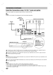
... "CH 3/4" jack (see drawing) from your Cable Box to the "CABLE IN" jack on your Antenna to the "CABLE IN" jack on the HD DVR with a coaxial RF cable. otes • Select "Cable box" menu option to watch cable programming via cable box. • Select "Digital" menu option... Box with a coaxial RF cable. Cable Box Connection Panel CABLE INPUT CH 3/4 VIDEO OUTPUT AUDIO OUTPUT INSTALLATION Cable TV Wall Jack Panel Antenna L R HD DVR Connection Panel Cable Box Controller Cable Box (front view) IR Sensor Cable Box (side view) 1/2" to 1" 1 Connect your cable box does not have "...
... "CH 3/4" jack (see drawing) from your Cable Box to the "CABLE IN" jack on your Antenna to the "CABLE IN" jack on the HD DVR with a coaxial RF cable. otes • Select "Cable box" menu option to watch cable programming via cable box. • Select "Digital" menu option... Box with a coaxial RF cable. Cable Box Connection Panel CABLE INPUT CH 3/4 VIDEO OUTPUT AUDIO OUTPUT INSTALLATION Cable TV Wall Jack Panel Antenna L R HD DVR Connection Panel Cable Box Controller Cable Box (front view) IR Sensor Cable Box (side view) 1/2" to 1" 1 Connect your cable box does not have "...

Owners Manual
Page 22
... IP-7, IP-55, IP-220 MV Camcorder Connection Panel DVHS Connection Panel MICRO MV DV IN/OUT Use only 4-pin connector HD DVR Connection Panel otes • The HD DVR does not allow daisy-chaining for IEEE-1394 devices. • Do not connect more than one kind of the "IEEE-1394" jacks... on the HD DVR with an IEEE-1394 cable. You can connect only one DVHS and one MV Camcorder. 22 IEEE-1394 Compatible devices We recommend that you connect a ...
... IP-7, IP-55, IP-220 MV Camcorder Connection Panel DVHS Connection Panel MICRO MV DV IN/OUT Use only 4-pin connector HD DVR Connection Panel otes • The HD DVR does not allow daisy-chaining for IEEE-1394 devices. • Do not connect more than one kind of the "IEEE-1394" jacks... on the HD DVR with an IEEE-1394 cable. You can connect only one DVHS and one MV Camcorder. 22 IEEE-1394 Compatible devices We recommend that you connect a ...